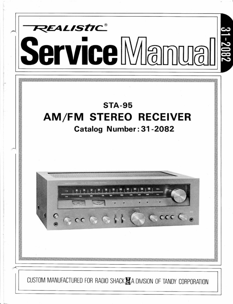
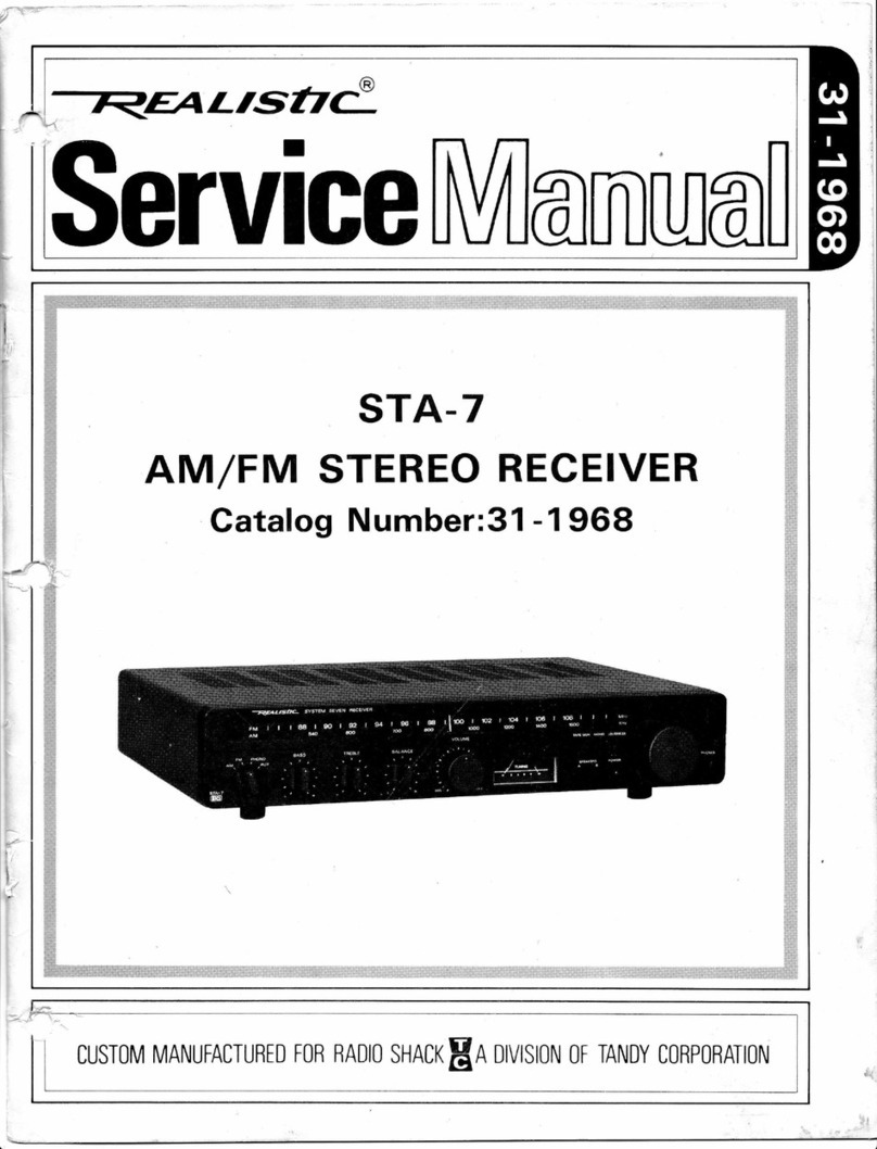
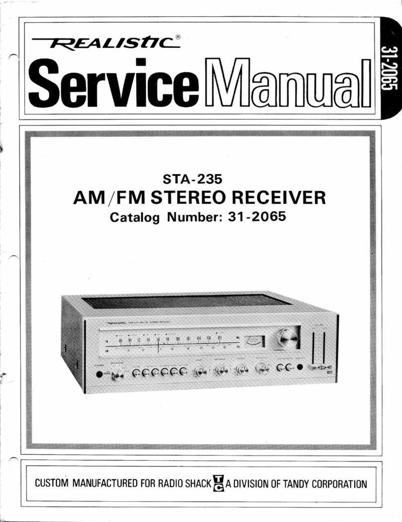
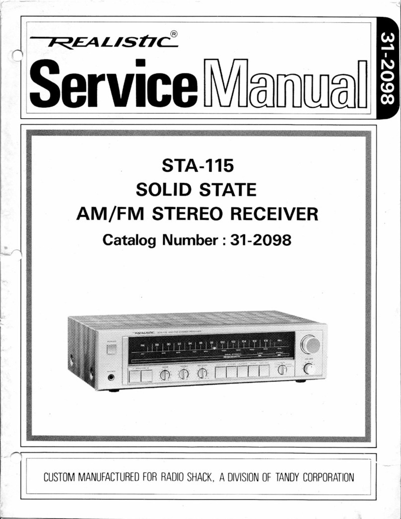
Realistic STA-78 User manual

ruLtsfiC
Serulce
STA.78
AM /FM STEREO
Catalog Number :
RECEIVER
31-2077
cusToM MANUFACTURED FoB RADIo sHACK In DMSIoN 0F TANDv conponAloN

(1)
(21
(3)
(4)
(5)
(6)
(71
(B)
(e)
( 10)
(11)
(121
( 13)
(141
( 15)
( 16)
(171
( 1B)
( 1e)
(20)
(211
CONTENTS
ELECTRICAL PERFORMANCE SPECI FICATIONS
DISASSEMBLY INSTRUCTIONS .
PAGE
3-5
BLOCK DIAGRAM
DIAL STRINGING
LEVEL DIAGRAM
ALIGNMENT INSTRUCTIONS
TROUBLESHOOTI NG
BRIEF DESCRIPTION OF PROTECTOR CIRCUIT
IC & TRANSISTOR LEAD IDENTIFICATIONS
AM/FM TUNER, IF & MPX P.C.B. (TOP & BOTTOM VIEWS) ....18
PHONO EOUALIZER AMP P.C,B. (TOP & BOTTOM VIEWS) .....19
TONE CONTROL P.C. B. (TOP & BOTTOM VIEWS) . . .2O
MAIN AMP P.C.B. (TOP & BOTTOM VIEWS) ,...,.21
swrTCH P. C. B. (TOP & BOTTOM VTEWS) ...22
NOISE MUTING P.C.B. (TOP & BOTTOM VIEWS) ,,.23
POWER SUPPLY P.C.B.(TOP & BOTTOM VIEWS) ,,,..,,,23
ELECTRICAL PARTS LIST
EXPLODED VIEW PARTS
IC INTERNAL DIAGRAM
5
6
1
7
12
16
16
17
DIAGRAM
8-
13-
33-35
36-37
38-39
{
{t
I
{
SCHEMATIC DIAGRAM
EXPLODED VIEW
-2-

i
1. ELECTRICAL PERFORMANCE SPECIFICATIONS
AM BAND
Frequency Coverage
IF
Usable Sensitivity for S/N 20 dB at 600 kHz
at 1000 kHz
at 1400 kHz
S/N Ratio at 5 mV/m input 1000 kHz
Selectivity at 1000 kHz a. 10 kHz
input = S/N 6 dB Sens. input
AGC Distortion at 1000 kHz, 80% mod. 100 mV/m input
AGC Figure of Merit
lF Rejection Ratio at 600 kHz
lmage Rejection Ratio at 1400 kHz
Bandwidth at 6 dB down
Distortion at 5 mV/m input, 30% mod.
Tape out Level at 5 mV/m input (RCA)
Tape out Level at 5 mV/m input (DlN)
Fidelity Bandwidth at 5 mV/m input (1 kHz = 0 dB)
Whistle Modulation of 2nd and 3rd harmonic, at 1 mV/m,
5 mV/m and 100 mV/m input
Dial Calibration at 600 kHz
at 1400 kHz
Overload: With a radiated signal of 1Ylm, the signal shall
breakup.
FM BAND
Frequency Coverage
IF
IHF Sensitivity at 90 MHz
at 98 MHz
at 106 MHz
New IHF
S/N 50 dB Ouiting Sensitivity at 90, 98 and 106 MHz
S/N Ratio at 'l mV input
3 dB Limiting Sensitivity
lF Rejection Ratio at 90 MHz
lmage Rejection Ratio at 106 MHz
Spurious Response and Cross Modulation
Capture Ratio
Alternate Channel Selectivity 100 pV input
Distortion at 1 mV input
Dial Calibration at 90 MHz
AFC Holding Range at 1 mV input
Temperature Range for Satisfactory operation
AM Suppression
Maximum Signal Handling Capacity
Tape out Level at 1 mV input (RCA)
Tape out Level at 1 mV input (DlN)
UNIT
kHz
kHz
pV lm
pV lm
pY lm
dB
dB
o/
/o
dB
dB
dB
kHz
o/
/o
mV
mV
Hz
%38
kHz 0 r,25
kHz 0 4.50
tunable without undue distortion or
32 25
48
50 42
35 28
45 38
6 4.5-9
0.8 2
200 200 *.2.5 dB
15 15 r 2.5 dB
50-2200 B0-1800
NOMINAL
510-1650
455
200
200
200
45
LIMIT
520-1620
500
500
500
40
be
UNIT
MHz
MHz
pV
pV
pV
dBf
pV
dBf
dB
pV
dB
dB
dB
dB
dB
o/o
kHz
kHz
"C
dB
mV
mV
mV
NOMINAL
86.5-109
10.7
1.9
1.9
1.9
10.8
2.8
14.2
65
1.8
85
5B
80
1.5
60
0.1
a.250
LIMIT
88- 1 0B
3.8
3.8
3.8
16.8
4.5
18.2
55
3.5
70
48
65
4
48
0.5
1 250
t250 +. 100
0-45
42
100
750 .t. 2.5 dB
15 a.2.5 dB
50
200
750
15
-3-
Muting Sensitivity
F requency R esponse ( De-emphasis)
75 pS (UL & C.S.A.)
50 pS (Australian)
25 pS (for FM Dolby)
All sets must meet the requirements of the FCC, FTZ.
FM STEREO BAND
Stereo I ndicator Sensitivity
Stereo Separation at 1 mV input
Stereo Distortion at 'l mV, 1 kHz
Pilot and Sub-carrier Leakage
AUDIO SECTION
at 100 Hz
at 1 kHz
at 10 kHz
input
lnput lmpedance PHONO MAG.
AUX
TAPE IN
Output Power, TH D 0.5% from 20 Hz to 20 kHz,
I ohms Both Channel Driven
Output Power, THD 0.5% at 1 kHz Both Channel Driven
Distortion at 5 W from 20 Hz to 20 kHz
Sensitivity for Rated Power (22W\
PHONO MAG.
AUX
TAPE IN
Frequency Response at AUX from 20 Hz to 20 kHz input,
1 W output
Bass Action at 100 Hz
Treble Action at 10 kHz
Min. Volume Hum & Noise
Signal to Noise Ratio PHONO MAG. (lnput shorted)
AUX (lnput 10 Kohm terminated)
TAPE lN (lnput 10 K ohm terminated)
Cross Talk at 1 kHz AUX Position
Loudness contour ch. at 100 Hz -30 dB Vol. position
Loudness contour ch. at 10 kHz -30 dB Vol. position
Channel Balance at AUX, Vol. = Max.
TAPE OUT Level PHONO MAG. (RCA)
AUX, (RCA)
PHONO MAG. Equalizer Response at 100 Hz
at 10 kHz
PHONO MAG. Over Load (THD = 0.5%)
DC Balance
UNIT
pV
dB
dB
dB
NOMINAL
5.5
UNIT
pV
dB
dB
dB
o/
/o
dB
UNIT
K ohm
K ohm
K ohm
NOMINAL
5.5
3B
48
35
0.5
50
NOMINAL
50
50
50
25
27
0.15
2.2
160
160
F lat
a.10
i.10
1
65
75
75
55
+9
+4
150
150
+ 13.1 1
-13.75
120
0
LIMIT
3.5-9.0
*1ae
_J
*1 oa
_J
1l an
LIMIT
3.5-9.0
28
33
28
1.5
45
LIMIT
22
24
0.3
2.2t3dB
160f3dB
160r3dB
*-2
a.10 L 2.5
r_10 i.2.5
3
55
65
65
45
+9 i 2.5
+4 r.2.5
r-2
150 r 3 dB
150 i.3 dB
*.2 dB
r_2 dB
90
*.30
W
W
o/
/o
mV
mV
mV
dB
dB
dB
mV
dB
dB
dB
dB
dB
dB
dB
mV
mV
dB
dB
mV
mV
-4-

Note:
The supply voltage is 120 volts AC (for UL & C.S.A.) and 24O volts AC for Australian models,
from a regulated power supply.
The power source must be insulated from other equipment connected antenna or output. The room
temperature is 25 degrees C.
Nominal Specs represent the design specs; all units should be able to approximate these - some will
exceed and some may drop slightly below these specs.
Limit Specs represent the absolute worst condition which still might be considered acceptable; in
no case should a unit perform to less than within any Limit Spec.
2. DISASSEMBLY INSTRUCTIONS
1) To remove Chassis f rom wooden cabinet.
Turn the cabinet upside down and re-
move the six screws from the bottom
cabinet. (Figure A)
2) Removal of Front Panel.
a) Remove the chassis from wooden
b) Pull out the Main Chassis.
c) Remove the two screws from the top
d) Remove knobs and pull off panel.
Figure A
cabinet as described in 1).
and three screws from the bottom of
(F igure B1 , B2l the Front Panel.
3)To remove Rear Panel from chassis.
Remove the four screws from the Rear
Panel. (F igure C)
Figure B1 Figure 82
-5-

a
E
U
Y
U
II
a
."'I
ri
-;- 1
E
5
9
t!
i'
-N
I
I
O
__.1
a
u
a
Eo
=o
oi
doo
ll' 9
3 e-
d LF
,E;- o?
50 i
ij*
i<
:33
or;'l -o
EE i oo
z
!
E;I
=Pg
66
<=N
="E
=o
EE
=
EF
3. BLOCK DIAGRAM
-6-

4. DIAL STRINGING DIAGRAM *START WITH CAPACITOR SET AT MINIMUM.
PLATES FULLY OPEN (UNMESHED).
*Pointer Position : HIGH END
@
5. LEVEL DIAGRAM
F
I
AUDIO FREQIJENCY. lkHz
-7-

6. ALIGNMENT INSTRUCTIONS
AUDIO CIRCUIT ADJUSTMENT,/CHECK
EOUIPMENT REOUIRED
1. DC Voltmeter
2. Audio Oscillator
3. Oscilloscope
4. AC Voltmeter
Note: "Maintain voltage at 12O volts AC, 60 Hz (UL, CSA)
(240 volts, 50 Hz AC for Australian models).
*Set SELECTOR Switch to AUX.
*Set MODE Switch to STEREO.
"See P.C.B. illustration for alignment points/adjustments.
For location of connection points and trimmer resistors, see P.C.B. view.
(-25mV to+25mV)
Figure 6
Oscilloscoge (Shorled OutpuiCondition)
(Normol Condiiion)
Figure 5
MAIN AMP ADJUSTMENT
STEP ADJUSTMENT EOUIPMENT CONNECTION AUDIO FBEO. LEVEL ADJUSTMENT
1
Check Balance by
measuring DC voltage
across Output Termi-
nal of L and R chan-
nel.
DC Volt
Meter See Figure 1No signal DC voltage should
be less than 25 mV
2
ldling current adjust-
ment DC Volt
Meter See Figure 2. No signal Adjust so voltage
across Emitter
resistors R633 anc
R634 is 5 mV
(8 ohm load).
VR601
VR602
Figure
CHECKING LIMITER CIRCUIT
STEP ADJUSTMENT EOUIPMENT CONNECTION AUDIO FREO SETTING LEVEL
1
Audio Osc.
V.T.V.M.
Oscilloscope
See Figure 3. 1000 Hz VOLUME: Max.
BASS, TREBLE
BALANCE:
center
Adjust input to
AUX to get out-
put level at just
the clipping point
(4 ohm load)
Figure 4.
2
Check the limiter
ci rcu i t. Audio Osc.
V.T.V.M.
Oscilloscope
See Figures 3,
5. 1000 Hz Same as above Check that output
dropt to a square
wave across R633
(R634) when out-
put speaker termi-
nals are shorted.
See Figure 6.
4ohm L.od ,A-.\
-(y
o{c ]- +)
AUDIO Osc. AUX SrA-79
( rooHz) Figure 3 Oscilloscope
<-7>
\1J
-8-

AM RF & IF ALIGNMENT
EOUIPMENT REOUIRED
1. AM Signal Generator
2. AC Voltmeter
3. Oscilloscope
4. Distortion Meter
Figure 7
Note: *Signal generator output should be no higher than necessary to obtain an output reading.
*Maintain line voltage at 12O volts, 60 Hz AC (UL & CSA) (240 volts, 50 Hz AC for Australian
models).
"Set SELECTOR Switch to AM.
*See P.C.B. illustrations for alignment points/adjustments and Figure 7.
osclLloscoPE DtsToRTloN
AC VOLTMETER METER
TAPE OUT
(LorR)
Figure 8
-9-
16)
lov@l
"-")"_,"ff,
r=-]
N]E
1203 tc20l
zMl
! 4" h,!
iNltNl il E: t^ '
:/ L'i ,t)l
r2o2 r2o3 ;I ti6 \
6d De , - |
6G_=_j r2or
STEP SIGNAL GENERATOR
COUPLING SIGNAL GENERATOR
FREOUENCY DIAL
SETTlNG INDICATOR ADJUSTMENT REMARKS
1
Connect standard loop
ANTENNA to Signal
Generator and radiate
signal into the AM Fer-
rite Antenna.
See Figure 8.
455 kHz
(400 H2,30% mod.) Point of
non-inter-
ference
(near
600 kHz)
Scope and,
AC Volt-
meter to
TAPE OUT
Jack.
r202
T203
(AM IFT)
Adjust for maxi-
mum reading on
meter.
2
Same as STEP 1. 510 kHz
(400 H2,30% mod.) Tuning
Gang
fully
closed.
Same as
STEP 1. L2O3 (AM OSC
Coil) Adjust for maxi-
mum reading on
meter. Refer to
Figures 7 and 8.
3
Same as STEP 11650 kHz
l4OO H2,30% mod.) Tuning
Gang
fully
opened.
Same as
STEP 1. TC105 (AM
OSC Trimmer) Adjust for maxi-
mum reading on
meter. Refer to
Figures 7 and 8.
4
Same as STEP 1600 kHz
(400 H2,30% mod.) 600 kHz Same as
STEP 1. L8O2 (AM ANT.
Coil) Adjust for maxi-
mum reading on
meter. Refer to
Figures 7 and 8.
5
Same as STEP 11400 kHz
(400 Hz, 30% mod.) 14OO kH,z Same as
STEP 1. TC104 (AM
ANT. Trimmer) Adjust for maxi-
mum reading on
meter. Refer to
Figures 7 and 8.
6Repeat STEPs 4 and 5 until no further change is noticed.
7
Same as STEP 11000 kHz
(400 kHz,30% mod.)
Output level to
100 mV/m
1000 kHz AM Signal
Meter on Set. VR201 Adjust so the
Meter Pointer
on Receiver is
at about 85%
of full scale.
2 -__.4 AM BAR ANTENNA
(6ocm) L/
\ l/_
/ffi @wfl

FM RF & IF ALIGNMENT
EOUIPMENT REOUIRED
1. FM Signal Generator
2. AC Voltmeter
3. Oscilloscope
4. Distortion Meter
5. CenterTuning Meter (1.2K ohm,200pA)
Note: "Signal Generator output should be no higher than necessary to obtain an output reading.
*Maintain line voltage at 120 volts, 60 Hz AC (U L & CSA) (240 volts, 50 Hz AC for Australian
models).
"Set SELECTOR Switch to FM.
"Refer to P.C.B. illustration and Figure 7 for test points/adjustments.
STEP GENERATOR
COUPLING GENERATOR
FREOUENCY D!AL
SETTING INDICATOR ADJUSTMENT REMARKS
1
Signal Generator to
FM Antenna Termi-
nal thru FM Dummy
Antenna (300 ohm)
98 MHz
(400 Hz
75 kHz dev.)
lnput: about
2-3 ttY
Near
98 MHz AC Voltmeter.
Scope and Dis-
tortion meter
to TAPE OUT
Jack (L or R).
T101 Adjust for maximum
reading on meter.
Refer to Figure 1 1.
2
Same as STEP 198 MHz
(400 Hz,
75 kHz dev.)
lnput: no input
(unit off )
Near
98 MHz Connect the
Center Tuning
Meter (1.2 kO,
200 pA) to Pin
No.12(+)and
No.13(-)on
AM/FM IF
Board (Refer
to Figures 7
and 9A.)
T201
(Primary) Adjust for Center
point on Center Tu-
ning Meter.
Refer to Figures 9,
9A, 10 and 1 1.
3
Same as STEP 198 MHz
(4OO Hz,
75 kHz dev.)
lnput: 1 mV
Same as
STEP 1. AC Voltmeter,
Scope and Dis-
tortion Meter
to TAPE OUT
Jack (L or R).
T201
(Secondary) Adjust for minimum
Distortion (about
0.1%). Refer to
Figure 9, 10 and 1 1.
4Repeat STEPs 1 ,2 and 3 until no further improvement is noticed.
5
Same as STEP 1. 90 MHz
(40O Hz,
75 kHz, dev.)
lnput: about
2-3 ttY
90 MHz Same as
STEP 1. L101 (FM
Antenna Coil)
1103 (FM RF
Coil-stretch or
squeeze)
Ll05 (FM OSC
Coil)
Adjust for maximum
reading on meter.
Refer to Figures 7
and 1 1.
b
Same as STEP 106 MHz
(400 Hz,
75 kHz dev.)
lnput: about
2-3 ttY
106 MHz Same as
STEP 1. TC 101(FM
Antenna Trim-
mer)
TC1O2 (FM RF
Trimmer)
TCl03 (FM OSC
Trimmer)
Adjust for maximum
reading on meter.
Refer to Figures 7
and 1 1.
7Repeat STEPs 5 and 6 until no further improvement is noticed.
8
Same as STEP 198 MHz
(400 Hz,
75 kHz dev.)
lnput: 5 trrV
98 MHz Same as
STEP 1. VR2O3 "MUTE" switched
"ON" and adjust
VR203 for no signal
output.
ISame as STEP 198 MHz
(4OO Hz,
75 kHz dev.)
lnput: 100 mV
98 MHz Signal Meter
on Set. vR202 Adjust so the Meter
Pointer on Receiver is
about 90% of full-scale.
-10-

T20t
Figure 9PATTERN
I
F.
i
I
coRE TURNING DlREcTloN (clockvise-A-8. Re. Fiqure9)
( r20l) Figure 1O
Canter Tunlng Mder
(l.2ko,2oOtA)
Figure 9A
FM EXT
Antenno Terminol (3OOn)
-11 -

FM STEREO ALIGNMENT
EOUIPMENT REOUIRED
1. Stereo Modulation Connect Stereo Modulator to EXT. Mod. terminal of FM SignalGenerator.
Modulation Level of 19 kHz Pilot Signal . . .8-1Oo/o.
2. FM Signal Generator . . Output Level - 1 mV
Frequency - Approximately 98 MHz
Deviation 75 kHz, 100% modulation of composite signal
3. Audio Generator
4. AC Voltmeter
5. Oscilloscope
6. Distortion Meter
7. Frequency Counter
Note: See P.C.B. illustration for alignment/test points.
Preliminaries
Set SELECTOR Switch to FM STEREO and MUTE Switch to "OFF" position.
MULTIPLEX & SEPARATION ALIGNMENT
STEP SIGNAL GENERATOR
COUPLING STEREO
MODULATION INDICATOR ADJUSTMENT REMARKS
1
Connect to FM Antenna
terminal thru FM dummy
antenna (300 ohm).
Mono. l kHz
(1000 Hz, No
Mod.)
lnput: 1 mV
Counter connected
to TP at Pin No. 12
of lC2O2.
VR2O5 Adjust for 19 kHz
1 50 Hz on Counter.
Refer to Figure 12.
2
Same as above. Composite MPX
Signal 1 kHz on
Left channel
ONLY.
AC Voltmeter con-
nector for TAPE
OUT Jack of Right
Channel.
vR204
(Separation )Adjust for minimum
reading on meter.
Refer to Figure 13.
3
Same as above. Composite MPX
Signal 1 kHz on
Right channel
ONLY.
AC Voltmeter con-
nector for TAPE
OUT Jack of Left
Channel.
Same as above. Same as above.
4Repeat STEPs 2 and 3 until AC Voltmeter reading is at least -40 dB same channel output.
(ie. 40 dB separation).
5
Same as STEP 1Composite MPX
Signal 1 kHz. AC Voltmeter con-
nected to TAPE
OUT Jack.
With 5.5 pV antenna in-
put signal, Stereo indi-
cator lamp should come
on.
FM STEREO ALIGNMENT SET.UP
ANTENNA
L(30On)
t61514t3t2|to
tc202 LA 3350
\r/ Q- 3OOn
FM EXT. AI
TERIVINAL(
STA-7€
REO MODULATOR FM SIGNAL GE
AC VTVM AI
U
99 (q-)
9? \V
99 Tl-'.-'
/
Figure 12
- 12-
Figure 13

7. TROUBLESHOOTING
SYMPTOM CAUSE,/ REMEDY
1 ) No output 1) Faulty AC power cord
Replace the cord.
2) Defective POWER switch
Replace the switch.
3) Broken wire in the Power Transformer
Replace the Transformer.
4) Blown primary switch
Replace the Fuse.
2) Pilot Lamp does not light. 1) Broken Lamp
Replace the Lamp.
2) Open in the Power Transformer tertiary winding
Replace the Transformer.
3) Pilot Lamp lights but no Speaker output. 1 ) Defective capacitor C802 or 803
Replace the defective capacitor(s).
2) Defective Rectifier D703
Replace the defective Rectifier.
3) Defect in the Power Transformer secondary winding
Replace the Power Transformer.
4) Blows Fuse 1) Defective Rectifier D703
Replace the defective Rectifier.
2) Short-circuit in the rectifier circuit
Remove the short.
3) Short-circuit in Power Transistor CircLitry TR611-614
Repair circuit and/or replace the defective Transistor(s).
5l " A" Speakers does not work. 1) Speaker Selector Switch defective
Replace the switch.
2l Poor contact in Speaker Output Terminals
Replace or repair it.
3) Poor contact in Speaker Selector Switch
Repair or replace it.
6) "B" Speakers does not work. 1) Speaker Selector Switch defective
Replace the switch.
2) Poor contact in Speaker Selector Switch
Repair or replace it.
3) Poor contact in Speaker Output Terminals
Repair or replace it.
7) No output one channel with VOLUME
at maximum and BALANCE at center,
when a test signal is applied to the
terminal of non-operating channel of the
BALANCE control VR502.
1) Defective Transistor TR501-503 or TR601-618
Replace the defective Transistor(s).
2) Defective resistor or capacitor of TONE and MAIN AMP circuit
Replace the defective part(s).
8) No output when a test signal is applied to
the input terminals, except PHONO input. 1) Defective MONO-Stereo or TAPE MONitor Switch
Repair or replace the Switch.
2) Defective SELECTOR Switch
Replace the Switch.
9) No output when a test signal is applied to
the PHONO input terminals. 1) Defective transistor, resistor or capacitor of PRE EO AMP circuit
Replace the part(s).
2) Defective MONO-Stereo or TAPE switch
Repair or replace the switch.
3) Defective SELECTOR Switch
Replace the SELECTOR Switch.
-13-

SYMPTOM CAUSE ,'REMEDY
10) Speaker works normally but Headphone
does not work. Defective R647 (Left) or R648 (Right)
Change it.
Headphone plug does not mate with jack
Replace the plug.
1)
2l
11) All the inputs work normally except
"AUX" input. 1) Poor contact in "AUX" input jack
Repair or replace it.
2l Poor contact in SELECTOR Switch
Repair or replace the switch.
12) "PHONO" input inoperative 1) Poor contact in "PHONO" input jack
Repair or replace it.
2) Faulty SELECTOR Switch
Repair or replace it.
13) "TAPE OUT" inoperative 1) Poor contact in "TAPE OUT" output jack
Repair or replace it.
14) "TAPE lN" inoperative 1) Poor contact in "TAPE lN" input jack
Repair or replace the jack.
15) "DUB OUT" inoperative 1) Poor contact "DUB OUT" jack
Repair or replace the jack.
16) No AM or FM (Tuner +B voltage is not
11 -12 V .l 1 ) Broken tertiary winding in the Power Transformer
Replace the Transformer.
2) Defective Diode D701
Change the defective diode.
3) Faulty capacitor C7O7,711 or 713
Replace the defective capacitor (s).
4) Faulty resistor R705 or 707
Replace the resistor(s).
5l Zener Diode D704 defective
Replace the Diode.
6) Short-circuit in Tuner +B circuit
Repair the short.
7) Poor contact in SELECTOR Switch
Repair or replace the Switch.
FM
No171 1) Poor contact in SELECTOR Switch
Repair or replace it.
2) lC, Transistor, diode, resistor, capacitor, inductor or IFT of FM
lF Board defective
Replace the defective part(s).
3) FM Front End defective
Replace the defective part(s).
4) Faulty FM Antenna lead-in/circuitry
Repair or replace the Antenna lead-in/circuitrv.
AMNo18) 1) Poor contact in SELECTOR Switch
Repair or replace Switch.
2) lC, Transistor, diode, resistor, capacitor or IFT of AM lF Board
defective
Replace the defective part(s).
3) Bar-Antenna Coil defective
Repair or replace it.
-14-

SYMPTOM CAUSE,/ REMEDY
19) No FM MPX Separation 1) lmproper adjustment
Readjust VR204 and 205.
2l lC2O2 of MPX board defective
Beplace the lC.
3) VR204, 205 defective
Replace the Trimmer Resistor(s).
4) Defective Transistor TR2O7,2OB or 2O9
Replace the defective Transistor(s).
20) No STEREO light or FM Stereo does
not work. 1) Broken STEREO lndicator Lamp
Replace the lamp.
2) Defective 1C202 ol FM MPX Board
Change the defective lC.
3) Defective Transistor f R207,208 or 209
Replace the defective transistor(s).
4l VR2O4,205 defective
Replace the defective Trimmer Resistor(s).
21) "LOUDNESS" has no effect. 1) Defective "LOUDN ESS" switch
Replace the switch.
Defective C501, 502 or R501,502
Replace the defective part(s).
z',t
22) "Stereo-MONO" not effective 1) Defective Stereo-MONO Switch
Bepair or replace the switch.
23) "MUTING" not effective 1) Defective MUTE Switch
Repair or replace the switch.
2) Defective Transistor TR206
Replace the defective Transistor.
3) Defective Trimmer resistor VR203
Replace the Trimmer resistor.
4) Defective Diode D207
Replace the Diode.
5) Defective 1C201
Beplace the lC.
241 "FM 25 ltS" not effective 1) Defective FM 25 pS switch
Replace the switch.
Defective C4O3 or 4O4
Replace the defective part(s).
2l
25) "TAPE MONlTOR" does not operate 1) Defective TAPE MONITOR switch
Replace or repair the switch.
26) "BASS" has no effect. 1) Faulty VR504 (100 K ohm control)
Replace it.
2) Defective C517-520 or R523-528 of TONE CONTROL Board
Replace the defective part(s).
27) "TREBLE" has no effect 1) Faulty VR503 (100 K ohm control)
Replace it.
2) Defective C513-516 or R517-522 of TONE CONTROL Board
Replace the defective part(s).
28) "AM/FM SIGNAL METER" NOt
functionlng 1) Defective AM/FM Signal Meter
Replace it.
- 15 -

SYMPTOM CAUSE,, REMEDY
2) ln case of FM reception, VR202, D206, C243, C244 or R24O
defective
Replace the defective part(s).
3) ln case of AM reception, VR201, D2O4, R242 or C237-239
defective
Replace the defective part(s).
4) Defective 1C201
Replace the lC.
8. BRIEF DESCRIPTION OF PROTECTOR CIRCUIT
(1) Limiting Circuit
lf speaker terminals are shorted, the output line (@line of Figure 14) is grounded and excessively
high current flows from collector to emitter of TR611 (TR612) and TR613 (TR614), and a high
voltage will appear across R633 (R634) and R635 (R636).
This high voltage goes to base of TR615 (TR616) and TR617 (TR618).
When the voltage between base and emitter increases to about 0.6 V, TR615 (TR616) and TR617
(TR618) will be turned on.
High current (input signal of TR607 [TR608]and TR609 [TR610]) f lows from collector to emitter
of TR615 (TR616) and TR617 (TR618) through D611 (D612) and D613 (D614), and collector to
emitter current of TR611 (TR612) and TR613 (TR614) willdrop as Figure 14 (from @to@',from
@to@) because of the output current limiting, and thus protect Power Transistors TR611 (TR612)
and TR613 (TR614).
lf this should occur, turn off the Receiver.
When the problem is corrected, turn the Receiver on again.
Figure 14
(21 Abnormal Temperature Rise Protection
lf the temperature of the MAIN Amp Heat Sink rises to 90oC, the Thermal Protector Switch will
activate to shut down A.C. Power to the entireReceiverand thus protect the MAIN Amp. lf this
should occur, turn the Receiver "OFF".
When the temperature of the MAIN Amp Heat Sink falls to within the operating limits of the
Receiver, the Thermal Protector Switch will reset itself.
When the problem is corrected, turn the Receiver on again.
SPEAKER
OUTPUT
^[
**-L
,I
erccxl
I
,l
'l
06il(0612)
tB6tI I RSta
l-*- *
R6B *
'"q;L,{ \
@
!@.
i6
E'
)L(
R655
(R636 )
-Fr 6
rn6rs +
:rR6r4) I
) o"o" rl
(06ro)J
\
{F
B
D6t3(D6t4)
-16-

8. IC & TRANSISTOR LEAD IDENTIFICATIONS
B
25C1175
254659
2SC536
2SCg30
25C929
2SC1 570
B
25C1674
2SCg00
2SC923
2SC945A
LA-3350
ffi
25D438
258560
-17-
HA-l1211

1O. AM/FM TUNER,
TOP VIEW
IF & MPX P.C.B.
(TOP & BOTTOM VTEWS)
BOTTOM VIEW

f
t
11. PHONO EOUALIZER
BOfiOM VIEW
AMP P.C.B.
(TOP & BOTTOM VIEWS)

12. TONE CONTROL p.C.B.(TOp & BOTTOM VIEWS)
TOP VIEW BOTTOM VIEW
IJJ
J(7)
coo
uJ r..)
tE.
F>
i=
-.6
ds
IJ
!-
-o
<to
JE
cn
ur) 'i
Loo
<ro
o$
-20-
This manual suits for next models
1
Other Realistic Stereo Receiver manuals

Realistic
Realistic STA-77L User manual

Realistic
Realistic STA-7 User manual

Realistic
Realistic PRO-2002 User manual

Realistic
Realistic STA-235B User manual

Realistic
Realistic STA-21 User manual

Realistic
Realistic STA-120B User manual

Realistic
Realistic STA-95 User manual

Realistic
Realistic STA-95 User manual

Realistic
Realistic STA-16B User manual

Realistic
Realistic PRO-2021 User manual