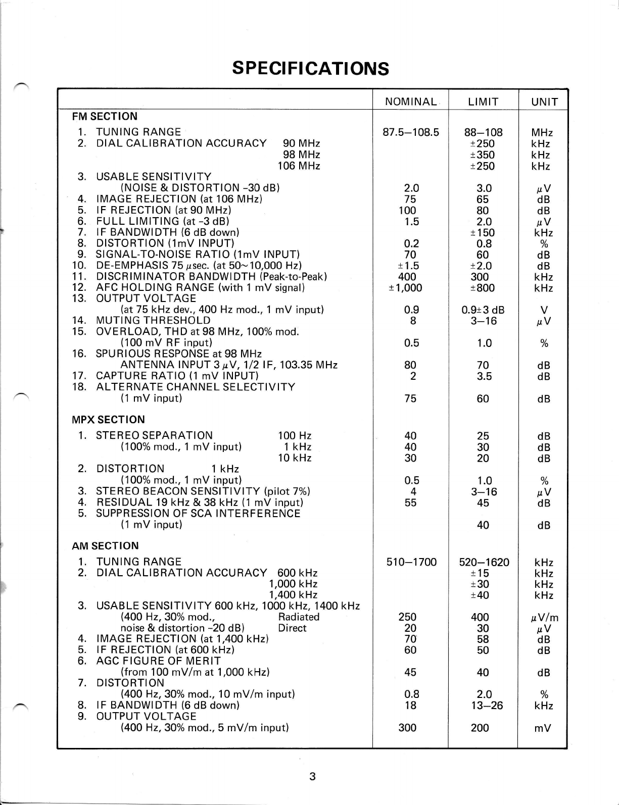
SPECIFICATIONS
NOMINAL LIMIT UNIT
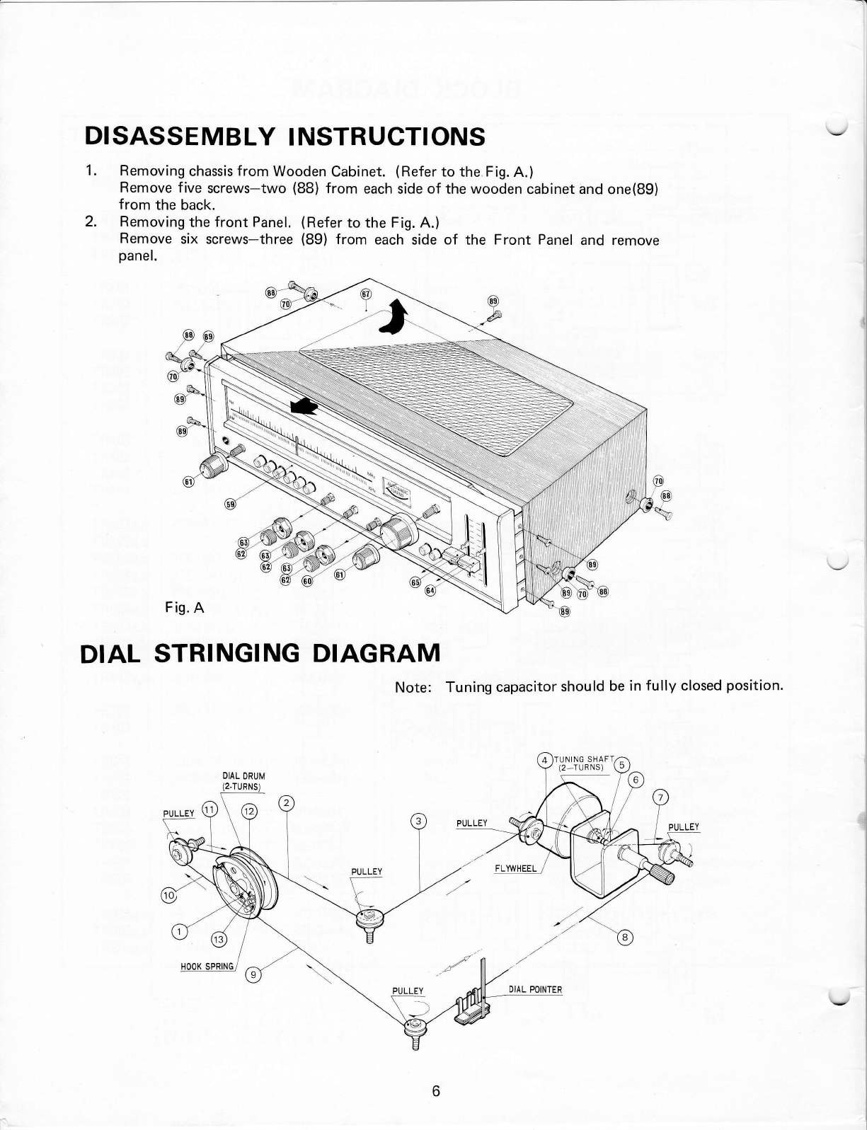
1.
2.
FM SECTION
TUNING RANGE
DIAL CALIBRATION ACCURACY 90 MHz
98 MHz
106 MHz
USABLE SENSITIVITY
(NOISE & DISTORTION -30 dB)
IMAGE REJECTION (at 106 MHz)
lF REJECTION (at 90 MHz)
FULL LIMITING (at -3 dB)
lF BANDWIDTH (6 dB down)
DISTORTION (1mV INPUT)
SIGNAL-TO-NOISE RATIO (1mV INPUT)
DE-EMPHASIS 75 psec. (at 50- 10,000 Hz)
DISCRIMINATOR BANDWI DTH (Peak-to-Peak)
AFC HOLDING RANGE (with 1 mV signal)
OI.,'TPUT VOLTAGE
(at 75 kHz dev., 4OO Hz mod., 1
MUTING THRESHOLD
OVERLOAD. THD at 98 MHz, 100%
(100 mV RF input)
SPURIOUS RESPONSE at 98 MHz
ANTENNA INPUT 3 pV,1/21F, 103.35 MHz
CAPTURE RATIO (1 mV INPUT)
ALTE RNATE CHANNE L SE LECTIVITY
(1 mV input)
3.
4.
5.
6.
7.
8.
L
10.
11.
12.
13.
14.
15.
16.
17.
18.
mV input)
mod.
MPX SECTION
1. STEREO SEPARATION
(1OOo/o mod., 1 mV input) 100 Hz
1 kHz
10 kHz
2. DISTORTION 1 kHz
(100% mod., 1 mV input)
3. STEREO BEACON SENSITIVITY (pilot 7%)
4. RESIDUAL 19 kHz & 38 kHz ('l mV input)
5. SUPPRESSION OF SCA INTERFERENCE
(1 mV input)
AM SECTION
3.
1.
2.
4.
5.
6.
TUNING RANGE
DIAL CALIBRATION ACCURACY 600 kHz
1,000 kHz
1,400 kHz
USABLE SENSITIVITY 600 kH2,1000 kHz, 1400 kHz
(4OO H2,30% mod., Radiated
noise & distortion -20 dB) Direct
IMAGE REJECTION (at 1,400 kHz)
lF REJECTION (at 600 kHz)
AGC FIGURE OF MERIT
(from 100 mV/m at 1,000 kHz)
DISTORTION
(4OO H2,30% mod., 10 mV/m input)
lF BANDWIDTH (6 dB down)
OUTPUT VOLTAGE
(400 H2,30% mod., 5 mV/m input)
7.
8.
9.
87.5-108.5
2.O
75
100
1.5
0.2
70
r 1.5
400
t 1,000
0.9
8
0.5
80
2
75
510-1 700
40
40
30
0.5
4
55
250
20
7A
60
45
0.8
18
300
88-108
t25O
t350
t25O
3.0
65
80
2.O
t'150
0.8
60
x2.O
300
t800
0.9r3 dB
3-16
1.0
70
3.5
60
25
30
20
1.0
3-16
45
40
520-1620
t15
t30
t40
40
2.0
13-26
200
400
30
58
50
MHz
kHz
kHz
kHz
pV
dB
dB
pV
kHz
o/
/o
dB
dB
kHz
kHz
o/
/o
dB
dB
dB
dB
dB
dB
V
pV
o/
/o
pV
dB
dB
kHz
kHz
kHz
kHz
pVlm
pV
dB
dB
dB
o/
/o
kHz
mV