Realistic STA-115 User manual

:EALrstC
Serulce
STA-115
SOLID STATE
I J INT L
AM IFM STEREO RECETVER
Catalog Number : 31-2098
CUSTOM MANUFACTUBED FOR RADIO SHACK, A DIVISION t]F TANDY CORPORATION

PAGE
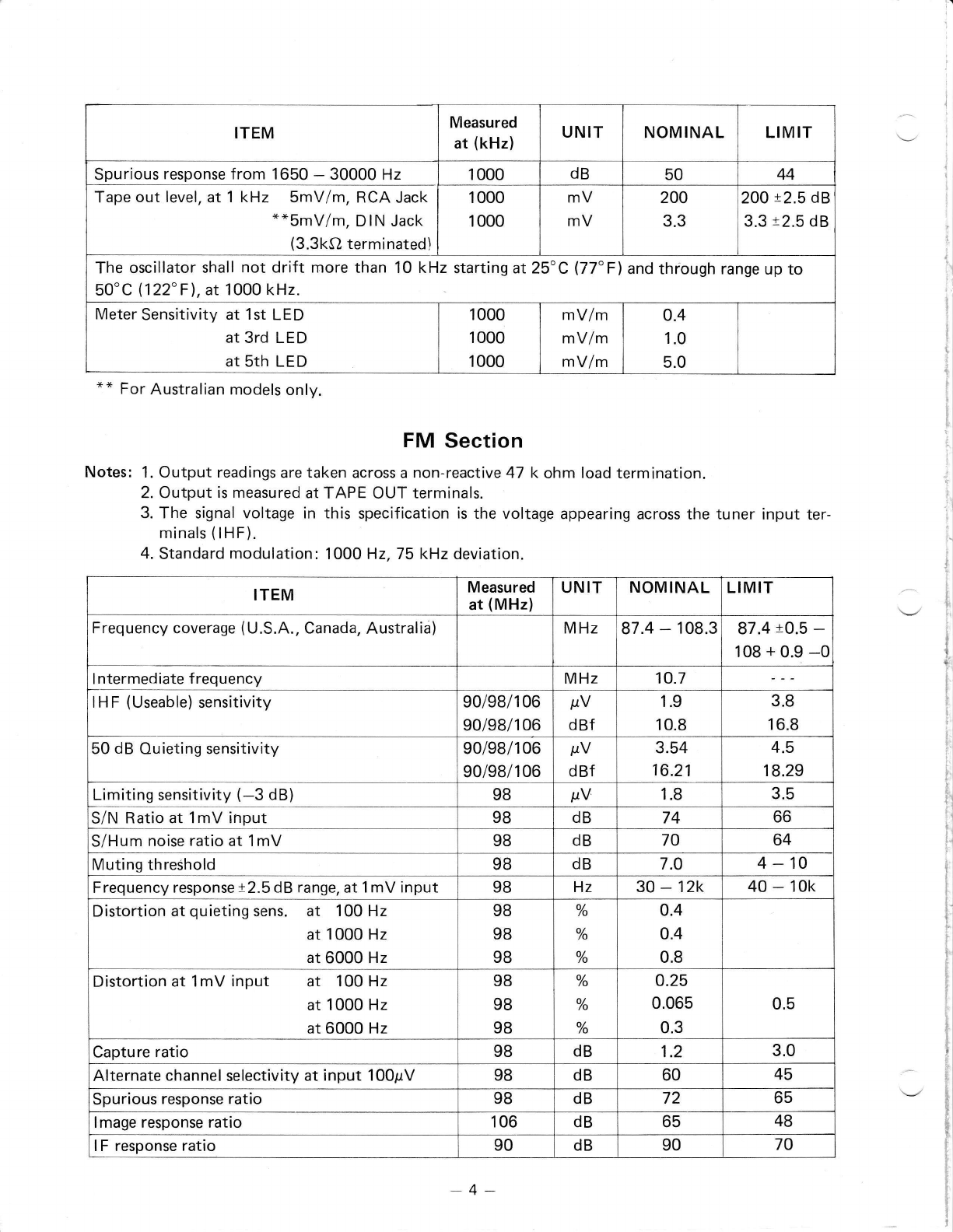
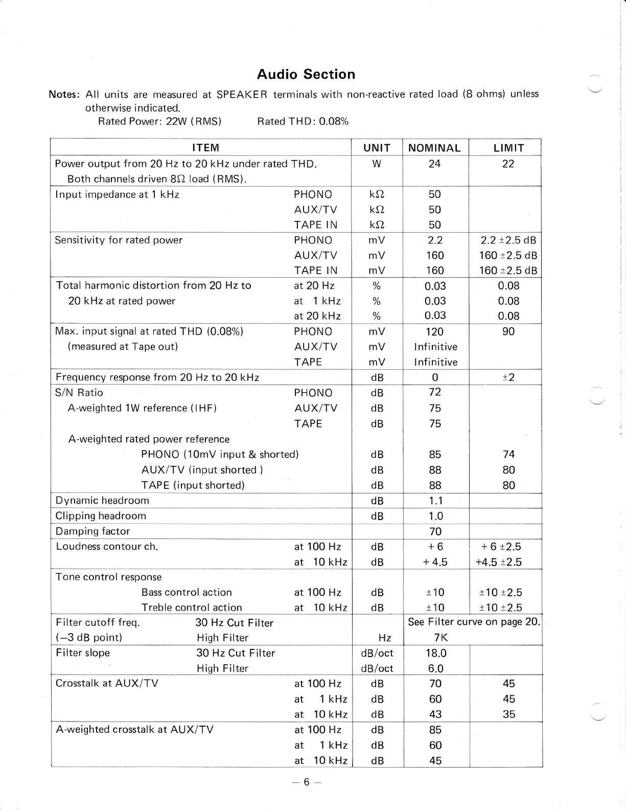
ELECTRICAL PERFORMIANCE SPECIFICATIONS ,,,,.. 3-7
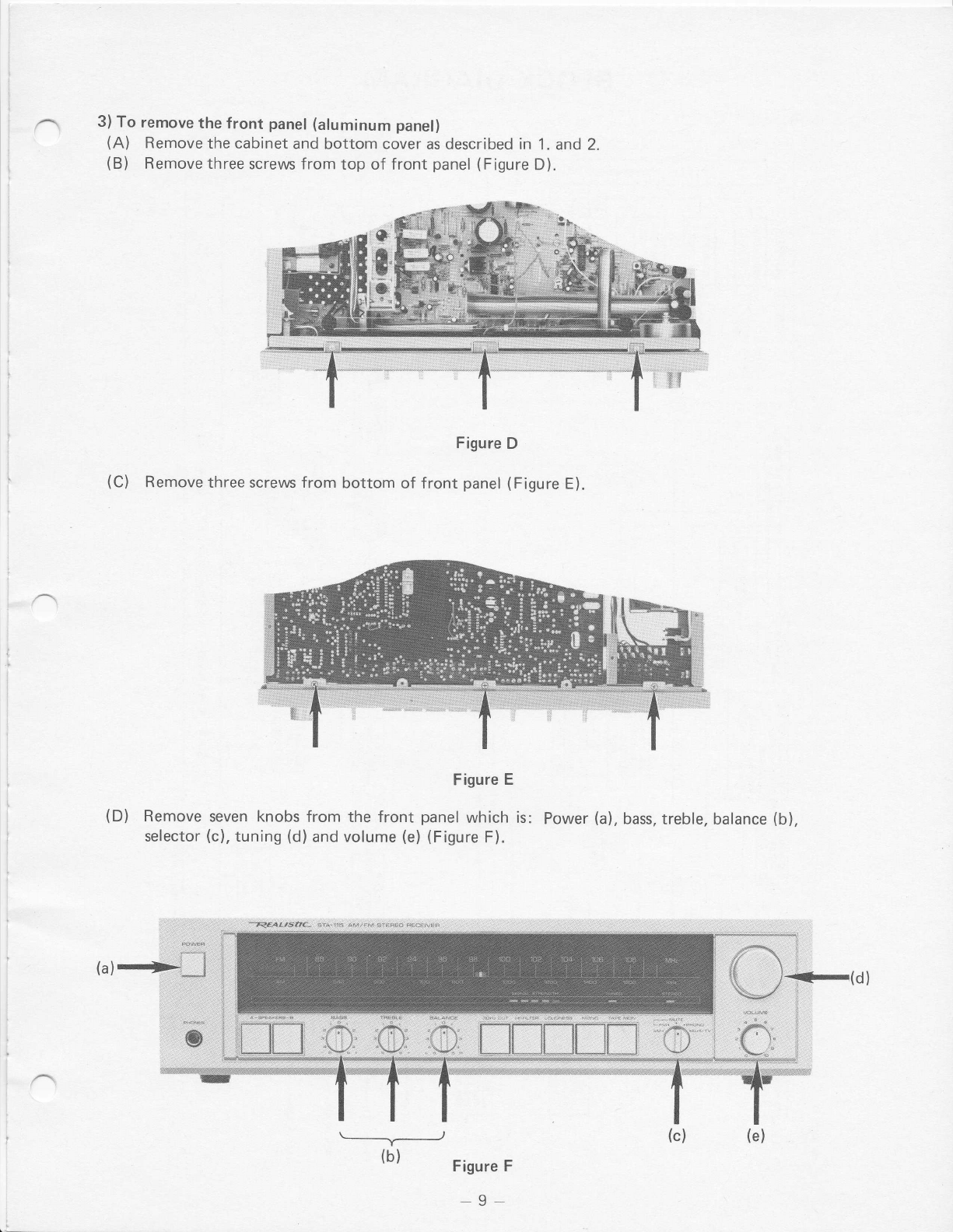
DISASSEMBLYINSTRUCTIONS. B-9
BLOCKDIAGRAM.. ...10
LEVEL DIAGRAM. ,.,..11
DIALSTRINGING DIAGRAM. ,,.,.,.11
CTRCU|TDESCRIPTION :..... .12-13
OPERATIONAL CHECK FOR CIRCUITS 14 - 26
ALIGNME NT I NSTRUCTIONS 27 -32
TROUBLESHOOTING... 33-35
TUNER AUDIO P.C.B, (TOP & BOTTOM VIEWS) 36 - 37
LEDP.C.B.(TOP&BOTTOMVIEWS). ..... .38
SPEAKERSWTTCH P.C.B. (TOP&BOTTOM VIEWS). .......39
DIAL POINTER P.C,B. (TOP & BOTTOM VIEWS) . . . ,39
WIRINGDIAGRAM ....40
EXPLODED VIEW 41 _- 42
ELECTRICALPARTSLIST. ....43-55
EXPLODED VIEW PARTS LIST . 56 -_ 57
TRANSISTOR LEAD IDENTIFICATION.. ...58
IC LEAD IDENTIFICATION & INTERNAL DIAGRAM. 59 - 62
SCHEMATIC DIAGRAM , .64- 65
PRODUCT,SAF'ETY NOrteE' ', ''",
,,,ManV.eiectric-al,and, rnech,anlcal" 'par.ts,,in ,this ihassii have specia|Ahaiaetefisties:,,:,f,heCe,e harActef',.;
r iiiiei,oitenlpiii1,unn,aiisld, ain6,.15e proiection,r61iqp6s6. by' them cannot necessarily be obtained
..'brVr,Using.iep'iacement, e:ompOnentsr, rated, toi:hi$her:,rvoltaggr,wattager,etc;, .Fle-pJater:nent,pails,thal::
, ,conipronents,,naving, sueS,,,isa,1u1s!,:6ie ioentitiea,bV er,,A ,!n the sche.matic diagram.,ahd,,the.nartii
list.
,..Beteieali+Oiaiing.,a,n17.of'tnese,ionrpoaenti.'reid:'16s parts list.i'n,this,ma"-u;l,,Careinjilfhi'tte ,
'.,sJnSiiiuta:rep'ljcrrnen,ttpiiii.,ihai.Ao noi:traie,,ifle'sarne,safety chaqacterlstics as specified in the
.)

ELECTRICAL PERFORMANCE SPECIFICATIONS
Whole Specs are measured under the following conditions:
1. The supply voltage is 120volts (U.S.A., Canada), (240voltsAC,50 Hzfor Australian models) from
a regulated power supply.
2. All measurements shall be taken under IHF measurement method unless otherwise specified.
3. The power source must be insulated from other equipment, connected to antenna or output.
4. The room temperature is 25'C l77"Fl.
AM Section
Notes: 1. Output readings are taken across a non-reactive 47 k ohm load termination.
2. Output is measured at TAPE OUT terminals.
3. The generator output shall terminate in an IRE loop antenna.
4. Standard modulation: 4OO H2,30% modulation.
ITEM Measured
at (kHz) UNIT NOMINAL LIMIT
Frequency coverage kHz 510 - 1650 520 - 1620
I ntermediate Frequency kHz 455
20 dB Ouieting sensitivit.y 600
1000
1400
pV lm
pV lm
pY lm
250
250
250
500
500
500
Sensitivity at antenna terminal 1 000 pV 20
S/N Ratio at 5 mV/m input 1 000 dB 43 37
Selectivity at S/N 20 dB input, r 10 kHz 1 000 dB 27 22
Band width at 6 dB down 1 000 kHz 64.5-9
A.G.C. Figure of merit 1 000 dB 50 42
I F rejection ratio 600 dB 32 27
lmaqe Reiection ratio 1400 dB 45 38
T.H.D. at 5mV/m input,30% mod. 1 000 o/
/o 0.8 2.O
Overload Distortion at 100mV/m input 80% mod. 1 000 o/
/o 3 5
Overload capacity at 80% mod.
at 30% mod. 1 000
1 000 mV/m
mV/m 200
200 100
100
Electrical audio f idelity
Ref ..freq. = 1 kHz, -O dB down, 5mV/m input 1 000 Hz 50-3k 80 - 2.5k
Whistle modulation (2nd) at SmV/m
at 100mV/m
(3rd) at 1mV/m
at 5mV/m
at 100mV/m
910
910
o/
/o
o,/
/o
5.0
10.0 10.0
15.0
1 365
1 365
isos
o/
/o
o/
/o
o/
/o
5.0
10.0
10.0
10.0
15.0
Frequency calibration 600
1 000
1400
kHz
kHz
kHz
0
0
x25
x40
r50
-3

ITEM Measured
at (kHz) UNIT NOMINAL LIMIT
Spurious response from 1650 - 30000 Hz 1 000 dB 50 44
Tape out level, at 1 kHz SmV/m, RCA Jack
**5mV/m, DIN Jack
(3.3kC} terminated)
1 000
1 000 mV
mV 200
3.3 200 r2.5 dB
3.3 t2.5 63
The oscillator shall not drift more than 10 kHz starting at25"C (77"F\and thfough range up to
50'C (122"F\, at 1000 kHz.
Meter Sensitivity at 1st LED
at 3rd LED
at sth LED
1000
1 000
1000
mV/m
mV/m
mV/m
o.4
1.0
5.0
** For Australian models only.
FM Section
Notes: 1. Output readings are taken across a non-reactive 47 k ohm load termination.
2. Output is measured at TAPE OUT terminals.
3. The signal voltage in this specification is the voltage appearing across the tuner input ter-
minals (lHF).
4. Standard modulation: 1000 H2,75 kHz deviation.
I
l
\-/ i
I
ii
I
i,l
jl
i
I
(
1
T
I
t
i
)
1
ll
1t
N
I
I
l
\-/ t
li
t
II
I
IL
tl
il
l1
il
il
rj
i
I
t.l
I
t1
rl
I]
I
il
dt
$l
\-/ tl
tl
[1
t
t
t
_l
ITEM Measured
at (MHz) UNIT NOMINAL LIMIT
Frequency coverage (U.S.A., Canada, Australia) MHz 87 .4 - 108.3 87.4 tO.5 -
108 + 0.9 -0
ntermediate frequency MHz 10.7
HF (Useable) sensitivity 90/98/1 06
90/98/106 pV
dBf 1.9
10.8 3.8
16.8
50 dB Ouieting sensitivity 90/98/106
90/98/106 pV
dBf 3.54
16.21 4.5
18.29
Limiting sensitivity (-3 dB) 98 pV 1.8 3.5
S/N Ratio at 1mV input 98 dB 74 66
S/Hum noise ratio at 1mV 98 dB 70 64
Muting threShold 98 dB 7.O 4-10
Frequency response t2.5 dB range, at 1mV input 98 Hz 30 - 12k 40 - 10k
Distortion at quieting sens. at 100 Hz
at '1000 Hz
at 6000 Hz
98
98
98
%
o/
/o
o/
/o
o.4
o.4
0.8
Distortion at 1mV input at 100 Hz
at 1000 Hz
at 6000 Hz
98
98
98
o/
/o
o/
lo
o/
/o
o.25
0.065
0.3 0.5
Capture ratio 98 dB 1.2 3.0
Alternate channel selectivity at input 100pV 98 dB 60 45
Spurious response ratio 98 dB 72 65
lmage response ratio 106 dB 65 48
lF response ratio 90 dB 90 70
-4-

I
FM Stereo Section
Notes: l.Outputreadingsaretakenacrossanon-reactive4T kohmloadtermination.
2. Output is measured at TAPE OUT terminals.
3. Signal voltage in this specification is the voltage appearing across the tuner input terminals
flHF).
4. Standard modulation: Main carrier (L+ R) -33.75 kHz (45%) dev.
Sub carrier (L - R) - 33.75 kHz (45%) dev.
Pitot (19 kHz) - 6.75 kHz (9%) dev.
Modulation frequency - 1000 Hz
ITEM Measured
at (MHz) UNIT NOMINAL LIMIT
AM suppression at 1mV inPut 9B dB 65 52
AFC holding range at 100prV input 98 kHz x250 t330
Calibration accuracy 90/98/1 06 kHz t25O
Tape out level, 1 mV input at RCA, 75 k dev.
**at Dl N, 22.5 k dev. 98
98 mV
mV 660
3.3 660 t2.5 dB
3.3 t2.5 dB
Meter sensitivity at 1st LE D
at 3rd LED
at Sth LED
9B
98
9B
pV
pV
pV
4.5
25.O
150
Temperature range for satisfactory operation "c 0-45
OF 32 - 113
Max. signal handling capacity 9B pV 200k
Auto-M Range at 1mV inPut 98 MHz tB00 t600
* * For Australian models only.
ITEM Measured
at (MHz) UNIT NOMINAL LIMIT
Stereo beacon switching and muting threshold 98
9B pV
dBf 7
22.13 5 - 15
19.21 -28.75
Stereo 50 dB quieting sensitivity 90/98/106
e0i98l1 06 pV
dBf 39.8
37.2
S/N Ratio at 1mV input (W/Low pass filter) 9B dB 71 55
Freq. response at 1mV input (50 - 10000 Hz) 98 dB t0 t2.5
Stereo distortion at 100 Hz
at 1mV input at 1 kHz
(WlLow pass filter) at 6 kHz
98
98
9B
%
o/
/o
o/
/o
0.8
0.2
0.8 1.5
Stereo separation at 1mV at 100 Hz
input at 1 kHz
at 10 kHz
9B
9B
98
dB
dB
dB
38
45
32
28
33
25
Sub-carrier product rejection 98 dB 39 32
SCA rejection 98 dB 50 45
Tape out level at 1 kHz, RCA Jack
1mV input 98 mV 600 60012.5 dB
-5-

Audio Section
Notes: All units are measured at SPEAKER terminals with non-reactive rated load (B ohms) unless \--l
otherwise indicated.
Rated Power: 22W (RMS) Rated THD: 0.08%
ITEM UNIT NOMINAL LIMIT
Power output from 20 Hz to 20 kHz under rated THD.
Both channels driven 8Sl load (RMS). W24 22
lnput impedance at 1 kHz PHONO
AUX/TV
TAPE IN
ke,
ko
ko
50
50
50
Sensitivity for rated power PHONO
AUX/TV
TAPE IN
mV
mV
mV
2.2
160
160
2.2 x2.5 dB
160 r2.5 dB
16012.5 dB
Total harmonic distortion from 20 Hzto at20 Hz
2OkHz at rated power at 1 kHz
at 20 kHz
o/
/o
o/
/o
o/
/o
0.03
0.0s
0.03
0.08
0.08
0.08
Max. input signal at rated THD (0.08%) PHONO
(measured at Tape out) AUX/TV
TAPE
mV
mV
mV
120
lnfinitive
I nf initive
90
Frequency response from 20 Hz to 20 kHz dB 0t2
S/N Ratio PHONO
A-weighted 1W reference (lHF) AUX/TV
TAPE
A-weighted rated power reference
PHONO (1OmV input & shorted)
AUX/TV (input shorted )
TAPE (input shorted)
dB
dB
dB
dB
dB
dB
72
75
75
85
BB
8B
74
80
80
Dynamic headroom dB 1.1
Clipping headroom dB 1.0
Damping factor 70
Loudness contour ch. at 100 Hz
at 10 kHz dB
dB +6
+ 4.5 + 6 12.5
+4.5 !2.5
Tone control response
Bass control action at 100 Hz
Treble control action at 10 kHz dB
dB t10
t10 t1O x2.5
t 10 t2.5
Filter cutoff freq. 30 Hz Cut Filter
(-3 dB point) High Filter Hz See Filter curve on page 20.
7K
Filter slope 30 Hz Cut Filter
Hioh Filter dB/oct
dB/oct 18.0
6.0
Crosstalk at AUX/TV at 100 Hz
at 1 kHz
at 10 kHz
dB
dB
dB
70
60
43
45
45
35
A-weighted crosstalk at AUX/TV at 100 Hz
at 1 kHz
at 10 kHz
dB
dB
dB
85
60
45
-6-

ITEM UNIT NOMINAL LIMIT
lM Distortion (SMPTE) o/
/o 0.08 o.2
Transient overload recovery time psec 15
Slew factor 3.5
Channel balance at V R max dB 0t 1.5
DC Balance at no signal and output mV 0t50
Tape out Level at RCA PHONO (input = 2.5mV)
Jacks (47kQ terminated) AUX/TV (lnput = 160mV) mV
mV 140
140 140 13 dB
140 t3 dB
""at DIN Jacks PHONO (lnput = 3.0mV)
(3.3kOterminated) AUX/TV (lnput=Z2OmYl mV
mV 3.3
3.3 3.3 t2.5 dB
3.3 t2.5 dB
Hum and noise at VR min. mV 0.8 2.O
Phono Eq. H IAA ch. from 2A Hz to 20 k Hz
(measured at Tape out) dB 10.5 t2.O
** Australian models only.
-7 -

DISASSEM BLY I NSTRUCTIONS
1) To remove the cabinet
(A) Remove two screws from each side of cabinet (Figure A).
Be careful not to lose the screw inserts when the screws are removed.
Figure A
Remove three screws from upper back panel (Figure B).
(B)
lt:it::t:L:l
l,t:t:t1i !:
t:t:i;!l;i i
:. _' :.:a
:.. 4:
:;t:l::ttt:i:.ffi
Figure B
2) To remove the bottom cover
(A) Turn the receiver upside down and remove twelve screws from the bottom (Figure C).
(B) Lift the bottom cover off .
i,.,..
Nir'.'
'Nil,.
ia.1.,l,'il
$Ni;rl
s$.4r.

3) To remove the front panel (aluminum panel)
(A) Remove the cabinet and bottom cover as described in 1. and 2.
(B) Remove three screltrs from top of front panel (Figure D).
Figure D
(C) Remove three screws from bottom of front panel (Figure E).
(D) Remove seven knobs from the front
selector (c), tuning (d) and volume (e)
Figure E
panel which is: Power (a), bass, treble, balance (b),
(Figure F).
\---_____Y__-__J
(b) Figure F
9-
:ariee4g$Ae- .$ta-lr* tlrrrM:qtqae':e€*rvrn

G_
P;
6@
J
LlJ
z
z
-
o
F
Lr
lrJ
J
o
o
o,
E
o
a
J
td
z
z
-
o
F
I
(,
(ts
2H
F-
-o
=R
=E
uts
E
u
Eo!
Iu --
:9cVo
,ou=o
^z)o --
5=9i-
za<)
i "o
F
]E
UU
Sf.
3tr
Xo
=x
=9
L- )Ei
g6; uo' n
dE3
Hze
F3, 3E3
<ze
6O >
c
==
Ze
9o
s{8
! oF
H=5
FiN
U J=
o >=
o
:
E
luu
!e
=l
J<
\E
ro
=l
LO
J
<E
zo )
0Fo
6*s
u=o
tao
ix
ZY
=<
oo
oE
UZ
J*
o
- uI
-drr
OU;
6b;
=@
G
P_
a*o
sx=
6-3
tIo
o<
JF
z
^-z a
'."f o
"'1 ts @
-= o
r
r
E-
<o
LN
=r
L
a
=
P;
l>
EE
=F
Io
E9
Etr
IF
5?
Eg
2E
o
L
\J
zz
oo
la
L\
Eo
>0
E
UIL
@F€
5Ia
uo 5
BLOCK DIAGRAM
I
I
I
I
I
I
L
I
I
___l
i*Ld[rHM
ia I I - I- ----l--1
ig + + : + + +
ig -s* **ExI tgJ
i ooJ I Go; I I a I
i _J | =ao I I I
I iE L[x;-] L=-.1
I Fo [Fr =
l"6o
uz
FO
l-
=l:=
'Za
=f
LL -
z
o
J
6
o
=
z
s
)
c
F
z
o
J
6
a
*
z
9r
LO
bF
==
ia
F
z
E
E
POWER TRANSFORMER
E
o_
ts^
JN
lo
u
E
g
9o
ko
JF
fo
0-
U
&
e
9o
JN
lo
0-
U
E
10

rTAPE IN
I
I
F
l
L AUX,/ TV
z
T
LpHotto
When stringing dial
1. Start with capacitor set at maximum.
(plates fully closed)
2. Pointer position should be at low end.
3. Start at tension spring.
4. Finish at eyelet.
LEVEL DIAGRAM
SPEAKER
O UTPU T
22w / AO
c)
3
)
UJ
UJ
)
70
60
50
28.4 dB
to.odB
30
20
to
o
37.2 dB
DIAL STRINGING DIAGRAM
PHONO
EQ AMP SWITCH TONE
CONTROL MAIN
AMP
AUDIO FREQUENCY ( lkHz )
- 11 *
Y]
@tr
-u-

CIRCUIT DESCRIPTION
PROTECTION CIRCUITS
The output from tone amp circuit to main amp circuit isswitched on/off with two FETsTR601 and
TR602. When pin 10 of 1C601 is high, the FETs are on; when low, FETs are off.
The switching will take place in the following three instances.
1 . Tu rn ing the receiver on and off ( F igure 1 )
When the power is switched on, both pins 1 and 2 of 1C601 are high, so pin 3 also becomes high and
hence pin 4 goes high. After the delay time set by the time constant R607 and C608, pin 10 of
1C601 becomes high and signals from the tone amp are fed to main amp. This time constant R607
and C608 is required to keep the speakers off to protect them from the switching transients.
At power off, DC voltage will not turn off immediately, so the AC portion is taken from the secon-
dary of the power transformer via D606 to pin 1 and 2. When this goes low, pin 3 goes low, C608 is
discharged by D602, and pin 10 goes low.
lo
TONE AMP
(L) lo
MAIN AMP
( L)
A!
I
I
lo B+
to B- D6O6 D6O2
Figure 1
2. Changing the selector switch position (Figure 2)
This prevents the switching noise from going to the speakers. The selector switch is a shorting type;
when it is turned from one position to another, the switch contact will make a momentary short
circuit to ground. This low level is applied to pin 12 of 1C601. Pin 11 goes low, pin 10 goes low
through the time constant circuit C607, D603 and R608. The time constant is required so the
cut- off condition lasts for about 0.3 to 0.6 seconds.
,o
MAIN AMP
(R)
-12-

3. Speaker terminal is shorted/low impedance speakers are used (Figure 3)
lf either of the above takes place, an excessively high current flows from emitter to collector of
TR511/TR512, and a voltage appears across R533/R534. This voltage is applied to gate of the
SCR601 via D505/D506. When this voltage exceeds 0.7V, SCR conductsand pin 13of 1C601 goes
low, C607 is discharged by D603, and pin 10 goes low. to
TONE AMP
(R)
Abnormal Temperature Rise Protection (Figure 4)
The STA-1 15 has two thermal protectors
lf the temperature of the main amp heat sink rises to 1O5"C1221" F (or power transformertemperature
rises to 95"C/20,3'F) the thermal protector switch makes an open circuit and the power supply will be
cut off. This protects the main amp and power transformer. ln this case, the amplifier automatically
shuts down and output will dropto 0V. lf this should occur,turn the receiveroff. When thetemper-
ature of the main amp heat sink falls to within the operating limits of the receiver, the thermal protec-
tor switch will reset itself. When the problem is corrected, turn the receiver on again.
AC
l2OV 6OHz
Figure 4
-13-
Y
zE
6r9
tsEE
IU;\
iIE
qE
2t9
E=H
rGts
cuo
>EE -;,t
lul
oo ;
Eol
6>l
\il
[- I
s# I
atl
ftq I
a-i I
or I
[o I
__l
I
z
a
I
,
z
F
d
)
I
i 38"
I EFs
t"
l*E"
t-
i
i
I:
rt Rch /o Rch
loRch
Figure 3
OF
UU
IJ
9F
El
=o
2e

OPERATIONAL CHECK FOR CIRCUITS
Power Supply Operation Check
[. aonn."t AC cord to standard AC power rorr...l
(o Power switch ON and dial lamp should light. )
(1) Check power supply circuit on
TUNER AUDIO P.C.B., fuses,
and power transformer.
(2) See TROUBLESHOOTING on
Page 33.
DC voltages are not correct.
DC voltages are correct.
START
CONNECTION
REPAIR -B+
+!
ro TONE CONTROL
& PROTECTOR
IB-
L"_
Proceed to next section
Audio Section Operation Check
(. Conn..t BO load to speaker output.
| . Connu.t DC voltmeters to C701 (minus [-]
( to ground) of main amp circuits on TUNER
i----
i_c_[e9(qo_ryeMp_p.!y_yo]t_ao_e_vyiLh_1q'IPyt_r
**Must be t30.5V IO.SV."*
(1) Check D701, C701, C702.
(2) Check for short-circuits.
(3) See T RO UB LESHOOTI NG on page 33.
DC voltage is not t31V t0.5V
DC voltage is t31V t0.5V
Figure 5
702 (
PC.B.
c702
DC VOLTMETER DC VOLTMETER
Figure 6
)andC
C.B.
ER AUDIO
nd
P.
TUI\
70t
UNE
)l
olm t*f]
CONNECTION
STEP 1
:CK
REP AIR
CH
t\ LJ
OK
1
to gr
AUD
-14-

iAdjust DC balance and idling current. r
l_s9e_4!r_GryV_ENIL\sIEqqr_r9rys_gLqage_?B_._i
[. Conn.., DC voltmeter to pin 11 (L) or pin 12 (R)l
( and GROUND of TUNER AUDIO P. C. B. )
DC VOLIMETER
Figure 7
i_.1.:f !iplqry:"_t_r_._*lrgs: g, L_.1J n .r,rr,".i"r.pr. ,"_'li1a ."]
*" within t50mV.*"
(1)CheckTR501 (L) orTR502 (R).
DC voltage over t50mV
DC voltage within t50mV
(:
[. Conn."t DC voltmeter to R531 (L ch) or R532 (R ch)J
Figure 8
icrrect< the idling "urlniot *rr" lrnp *i.1 "" i"p;.- -
tCheck the DC voltage across emitter resistor R529 (R531) (L ch) and
lnsso (Rb32) (R ch).
**should be 2.35mV +4.71-1.88mV. *"
(1) Check the value of R519 (L ch) and R520 (R ch).
IFor Australian models, adjust VR 501(L ch) and VR 502 (R ch).]
(2) Check the bias circuit of D501, D503 (L ch) and/or D502, D504 (R ch).
(3) Check TR503 (L ch) and TR504 (R ch).
(4) Check TR501, (L ch) and TR502 (R ch).
(5) Check for short-circuits on TUNER AUDIO P.C.B.
DC voltage is above 7.05mV or below 0.47mV.
DC voltage is 2.35mV +4.71-1.BBmV.
'i
I
I
I
I
I
I
ADJUSTMENT
REPAIR
- 15 -

CONNECTION
REPAIR
ADJUSTMENT
R EPAIR
CHECK
(.
l.
l.
t
Connect oscilloscope and V.T.V.M. to speaker terminal. 'l
Connect 8O load to speaker output. ]
Connect audio osc. to input of main amp circuit: C501s plus (+) side (L),1
and/or C502s plus (+) side (R) |
lnput should be 500mV and output should be 13.3V (at 1 kHz) )
OSCILLOSCOPE VIV.M
auDro osc. TUNER,AUDTO PC.3 en LoAo
Figure 9
t--------------l
l-c_ry 9 L l"l 1yl]l.l rl.3 l_c I i p p i n_s _o f 9 lt! lt :,! 1u L y1: $i q g _i
* * lnput level should be about 600mV to 1.0V.*"
(1) Check TR501, 503, 505, 509 (L) and TR502, 504, 506, 510 (R),
(2) Check STEP 2 and STEP 3.
(3) Check main amp. circuits.
Output signal wave is not clipping symmetrically.
NOT GOOD
^v Figure 10
Symmetrical clipping (balanced) of output signal
iAJ;rit "riprtlA, *oio oiC.IItnri
SYMMETRICAL
(jusi bcginninO to clip)
WAVC.
to produce 22 watts rated output
iQn* t,f" ".1i" .*n_Sq.q,
"* should be about 28.4 dB.*"
OUTPUT voltaqe
(dB = 2u ros rNpurr *rtE-')
(1) Check main amp circuits.
(2) CheckSTEPs 1,2,3 and4.
lnput level is not 500mV l2 dB.
lnput level is at least 500mV t2dB for rated output power.
Proceed to next section. -16
(+)

Preamp Operation Check
Connect audio osc. to PHONO input.
connect oscilloscope and V.T.V.M. with decibel scale to TApE oUT jack.
Set SE LECTOR switch to pHONO.
Figure 11
(.
l.
[.
"* RIAA Curve **
[loo n, - + 12.9 dB\
( t r.Hr-odB )
\r o rHz - -13.7 dB )
(1)
(21
(3)
Figure 12
2o ,@ Auoo I x
Check 1C301.
Check C309, C31 1, R309, R31 1 ( L ch) and C310, C512, R310, R31 2
(R ch).
Check PRE amp circuits.
Equalization response at 100 Hz does not fallwithin + 12.g (RIAA) !2dB
and 10 kHz does not fall within -13.7 (RtAA) t2 dB.
Equalization response falls within + 12.9 (RIAA) 12 dB at 100 Hz and
-13.7 (RIAA) !2dB at 10 kHz.
OSCILLOSCOPE
DtroooD!trtrtro o
T----
L 9 !1"5 _tl'_P_lolo_ :. g,_u !.3! gy9T9 11.: ]
REPAIR
Proceed to next section.
-11 -

CONNECTION
Tone Control Operation Check
Connect audio osc. to AUX/TV input jack.
Connect oscilloscope and V.T.V.M. to speaker terminal.
Connect BO load to speaker output.
Set SELECTOR switch to AUX/TV position.
TAPE MONITOR: OFF
MONO switch: STEREO
LOUDNESS: OF F
a
a
a
a
o
a
a
oscrlloscoPE v_ T- v. M.
auDr o osc.
f--- --
iCfreck BASS action at 100 Hz. i
t_ _ _ - _ _ _ ___t
** TONE CONTROL Curve"*
Figure 14 roo rk
* AUDIO FREQUENCY (Hz)
(1) Check bass control circuit on TUNER AUDIO P.C.B.
(2) See TROUBLESHOOTING on page 35.
Frequency response does not fall within 11012.5 dB.
Frequency response falls within t 10 t2.5 dB.
G +ro
3
l!
2o
I
I
a
u -to
E.
t
trtroooDtrUtrCo O
sTA - ll5
Figure
TONE CONTROL CURVE
.lOO Hz EASS
t ro kH, tneeLe )
R EPAIR
-18-

REPAIR
REPAIR
p!e+ r*Eii1t,et 1,tq [tal
*" TONE CONTROL Curve (Figure 14)*"
(1) Check treble control circuit on TUNER AUDIO P.C.B.
(2) See TROUBLESHOOTING on page 35.
Frequency response does not fall within t1012.5 dB.
Frequency response falls within t 10 i2.5 dB.
Check LOUDNESS compensation at 48mV R-MS;tp;tl.r"r]
*"LOUDNESS Curve"*
Figure 15
roo tr
+ AUDIO FBEQUENCy (Hz)
(1) Check loudness circuit on TUNER AUDIO P.C.B.
(2) See TROUBLESHOOTING on page 35.
Loudness compensation does not fall within + 6 t2.5 dB at 100 Hz and
+ 4.5 t2.5 dB at 10 kHz.
Loudness compensation falls within + 6 !2.5 dB at 100 Hz and + 4.5 t2.5
dB at 10 kHz.
Proceed to the next section.
ll)
g
r..u
t,
z
o
e^
a+b
UJ
cc +4.5
l.
(-30 dB volume position) i
-19-

REPAIR
CHECK
REPAIR
14
12
10
8
6
4
2
dB0
-4
-6
-8
_10
-12
-t4
i Ch."k n-igl-'-ti lGislop. rflt n, tcrt oirlieqff"yil
** FILTER Curves (Figure 16)""
(1) Check high filter circuit on TUNER AUDIO P.C.B.
(2) See TROUBLESHOOTING on page 35.
Filter slope is less than 6.0 dB/oct at7 kHz.
Filter slope is better than 6.0 dB/oct at 7 kHz.
;_C_ne_cl<_3Q_tlz_cy1!i!t9r_slorqy,_t!!ryr_qollrgt_Uil j
"*FILTER Curves (Figure 16)**
(1) Check 30 Hz cut filter circuit on TUNER AUDIO P.C.B.
(2) See TROUBLESHOOTING on page 35.
Filter slope is less than 18.0 dB/oct.
Filter slope is better than 18.0 dB/oct.
FILTER CURVES
100 Frequency (Hz)
Figure 16
30 Hz ut Filter : OFF
\'i:=-- \
,( \
\.o I
Hz Cut Fi o*\
BA{iS Contrr
lMax Hqh-F Iter I
OFF
I
I
,/
I--
II'T
lt /3OHzC Filter :
I)N
lt
IJU riz uut Frlter
IUFF
II
10
-20-
1k 10k
This manual suits for next models
1
Table of contents
Other Realistic Stereo Receiver manuals

Realistic
Realistic STA-235B User manual

Realistic
Realistic STA-95 User manual

Realistic
Realistic STA-16B User manual

Realistic
Realistic STA-720 User manual

Realistic
Realistic STA-95 User manual

Realistic
Realistic STA-120B User manual

Realistic
Realistic STA-7 User manual

Realistic
Realistic STA-85 User manual

Realistic
Realistic 31-2080 User manual

Realistic
Realistic STA-78 User manual