Rebel MIE-RB-266 User manual

TOOLS
model: MIE-RB-266
USER’S
MANUAL
DE EN PL RO
CLAMP METER

DE 2

DE
3
SICHERHEITSANWEISUNGEN
Um einen elektrischen Schla , oder Verletzun en zu
vermeiden, befol en Sie die unteren Sicherheitsanweisun en:
1. Überprüfen Sie das Gehäuse vor der Verwendun des
Geräts auf mechanische Beschädi un en. Verwenden Sie
das Gerät nicht, wenn das Gehäuse Risse aufweist oder
Teile fehlen.
2. Überprüfen Sie vor der Verwendun des Geräts die
Messleitun en auf Beschädi un en. Verwenden Sie das
Gerät nicht, wenn die Messleitun en Isolationsschäden
oder Schnitte aufweisen.
3. Geben Sie keine höheren Spannun en als in der
Spezifikation an e eben ein.
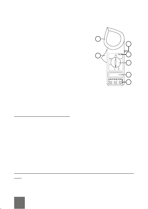
4. Ändern Sie während der Messun en nicht die Position des
Drehschalters.
5. Treen Sie besondere Vorsichtsmaßnahmen, wenn Sie
Spannun en über 60 V DC und 30 V AC messen.
6. Vor der Messun den Drehschalter in die richti e Position
brin en und die Messleitun en an die richti en Buchsen
anschließen.
7. Verwenden Sie das Gerät nicht bei Temperaturen, die den
an e ebenen Bereich überschreiten, bei hoher
Luftfeuchti keit und in der Nähe von Spren stoen und
brennbaren Stoen.
8. Halten Sie während der Messun die Messleitun en über
den Fin erschutz.
9. Trennen Sie vor dem Messen den Messkreis vom
Stromnetz und entladen alle Kondensatoren.
10.Wenn auf dem Display das Symbol für niedri en
Batteriestand an ezei t wird, wechseln Sie die Batterie.
Andernfalls kann die Genaui keit der Messun en
verrin ert werden.
11. Vor dem Önen des Batterie ehäuses die Messleitun en
vom Messkreis und vom Gerät trennen.
12.Die Batterie muss durch eine neue mit derselben
Spezifikation ersetzt werden.
13.Manipulieren Sie nicht die internen Schaltkreise des
Geräts. Dies kann zu einer Verrin erun der Genaui keit
oder zu einer Beschädi un des Geräts führen.

14.Das Gerät ist nur für den Innenbereich bestimmt.
15.Nehmen Sie die Batterie heraus, wenn das Gerät län ere
Zeit nicht benutzt wird.
PRODUKTBESCHREIBUNG
1. Klemme
2. Taste Klemme entrie eln
3. Taste Messun einfrieren
4. Buchse für Thermoelement
5. Drehschalter
6. Display
7. Anschlussbuchsen
BETRIEB
• Drücken Sie die Taste Messun einfrieren um den
aktuellen Messwert zu halten. Drücken Sie erneut die Taste
Messun einfrieren um zum aktuellen Messwert
zurückzukehren.
Wechselstrommessung [AC
1. Stellen Sie den Drehschalter auf Position 1000 A. Wenn auf
dem Display eine bis mehrere führende Nullen an ezei t
werden, stellen Sie den Bereich auf 200 A oder 20 A ein.
2. Le en Sie den emessenen Draht zwischen die Klemmen
senkrecht zum Mess erät und in den mittleren Teil
zwischen die Klemmen und stellen sicher, dass die
Klemmen eschlossen sind. Wenn mehr als ein Draht
zwischen den Klemmen platziert wird, ist die Anzei e
mö licherweise un enau.
3. Das Er ebnis wird auf dem Display an ezei t.
Wechselspannung und Gleichspannungs-Messung [AC &
DC
1. Verbinden Sie die rote Messleitun mit der VΩ Buchse.
2. Verbinden Sie die schwarze Messleitun mit der COM
Buchse.
1
2
3
4
5
7
6
DE 4

DE
5
3. Stellen Sie den Drehschalter auf den richti en
Spannun sbereich. Wenn der Bereich nicht bekannt ist,
stellen Sie den Bereich auf den höchsten Wert ein und
verrin ern diesen schrittweise, bis die enaue Messun
erhalten wird.
4. Verbinden Sie die Messleitun en mit dem Messkreis.
5. Schalten Sie den Messkreis ein. Das Er ebnis wird auf dem
Display an ezei t.
Widerstandsmessung
1. Verbinden Sie die rote Messleitun mit der VΩ Buchse.
2. Verbinden Sie die schwarze Messleitun mit der COM
Buchse.
3. Trennen Sie den Messkreis vom Stromnetz und entladen
alle Kondensatoren.
4. Verbinden Sie die Messleitun en mit dem Messkreis.
5. Das Er ebnis wird auf dem Display an ezei t.
Temperaturmessung
1. Stellen Sie den Drehschalter auf °C oder °F.
2. Schließen Sie das Thermoelement an die Buchse an
(achten Sie auf die richti e Polarität).
3. Die Temperatur wird an ezei t.
Messung des Isolationswiderstands
1. Stellen Sie den Drehschalter auf 2000 MΩ. Instabiles
Lesen ist normal.
2. Verbinden Sie den Tester (optional, nicht im Set) mit den
Anschlussbuchsen.
3. Stellen Sie den Drehschalter auf 2000 MΩ.
4. Verbinden Sie die Messleitun en mit dem Messkreis.
5. Schalten Sie das Mess erät ein.

REINIGUNG UND WARTUNG
• Reini en Sie das Gerät mit einem weichen, leicht feuchten
Tuch ohne Scheuermittel.
• Um die Batterie zu wechseln, lösen Sie die Schraube am
Batteriefachdeckel. Ersetzen Sie die Batterie (beachten Sie
die Polarität) nach dem Önen des Batteriefachdeckels.
Schließen Sie den Batteriefachdeckel und schrauben die
Schrauben ein.
TECHNISCHE DATEN
Gleichspannung [DC
Überlastschutz: 250 V AC für 200 mV Bereich; 1000 V DC
oder 750 V für alle Bereiche.
Wechselspannung [AC
• Durchschnittliche Antwort kalibriert in Eektivwert einer
Sinuswelle.
• Frequenzbereich: 45 Hz ~ 450 Hz
• Überlastschutz: 1000 V DC oder 750 V für alle Bereiche
Bereich Auflösung Genauig eit
200 mV 100 µV ±(0,5% + 3)
2 V 1 mV
±(0,8% + 5)20 V 10 mV
200 V 100 mV
1000 V 1 V ±(1% + 5)
Bereich Auflösung Genauig eit
200 V 100 mV ±(1% + 5)
750 V 1 V ±(1,2% + 5)
DE 6

DE
7
Durchgangsprüfung
Überlastschutz: für 15 Sekunden in Max. 220 V.
Widerstand
• Max. Spannun des oenen Schaltkreises: 3 V
• Überlastschutz: für 15 Sekunden in Max. 220 V.
Temperatur
Bereich Auflösung Genauig eit
200 Ω 0,1 Ω ±(1% + 10)
2 KΩ 1 Ω
±(1% + 4)
20 KΩ 10 Ω Buchse
200 KΩ 100 Ω
2 MΩ 1 KΩ
Bereich Auflösung Genauig eit
-40°C ~ 150°C 1°C ±(1% + 4)
150°C ~ 1370°C ±(1,5% + 15)
-40°F ~ 302°F 1°F ±(1% + 4)
302°F ~ 1999°F ±(1,5% + 15)
Bereich Beschreibung
Wenn der Widerstand
niedri er als 30 Ω ± 20 Ω ist,
ertönt der Summer

DE 8
Wechselstrom [AC (Durchschnittliche Antwort kalibriert in
Eektivwert einer Sinuswelle)
• Überlastschutz: 1200 A
• Klemmenönun : 53 mm
Isolationstest (mit optionalem Isolationstester 500 V)
Bereich Auflösung Genauig eit
20 MΩ 10 KΩ ±(2% + 2)
2000 MΩ 1 MΩ
±(4% + 2) für 500 MΩ und
kleiner
±(5% + 2) für andere
Bereich Auflösung Genauig eit (50 Hz
~ 60 Hz)
20 A 10 mA ±(2,5% + 13)
200 A 100 mA
1000 A 1 A
±(2,5% + 8) für
800 A und kleiner
Referenz nur für
Messun en über
800A

DE
9
Deutsch
Korre te Entsorgung dieses Produ ts
(Ele tromüll)
(Anzuwenden in den Ländern der Europäischen Union und anderen
europäischen Ländern mit einem separaten Sammelsystem)
Die Kennzeichnun auf dem Produkt bzw. auf der dazu ehöri en Literatur ibt
an, dass es nach seiner Lebensdauer nicht zusammen mit dam normalem
Haushaltsmüll entsor t werden darf. Entsor en Sie dieses Gerät bitte etrennt
von anderen Abfällen, um der Umwelt bzw. der menschlichen Gesundheit nicht
durch unkontrollierte Müllbeseiti un zu schaden. Recyceln Sie das Gerät, um
die nachhalti e Wiederverwertun von stoichen Ressourcen zu fördern.
Private Nutzer sollten den Händler, bei dem das Produkt ekauft wurde, oder
die zuständi en Behörden kontaktieren, um in Erfahrun zu brin en, wie sie das
Gerät auf umweltfreundliche Weise recyceln können. Gewerbliche Nutzer
sollten sich an Ihren Lieferanten wenden und die Bedin un en des
Verkaufsvertra s konsultieren. Dieses Produkt darf nicht zusammen mit
anderem Gewerbemüll entsor t werden.
Her estellt in China für LECHPOL ELECTRONICS Sp. z o.o. Sp.k.,
ul. Garwolińska 1, 08-400 Miętne.

EN 10
SAFETY INSTRUCTIONS
In order to avoid electric shock or other injuries, follow the
safety instructions below:
1. Before usin the device, inspect the case for any
mechanical dama e. If the case has cracks or is missin
any part, do not use the device.
2. Before usin the device, check the test leads for any
insulation dama e. If the test leads has insulation dama e
or cuts, do not use the device.
3. Do not input volta es hi her than said in the specification.
4. Durin measurements, do not chan e the position of the
rotary switch.
5. Take extra precaution while measurin volta es above 60
V DC and 30 V AC.
6. Before measurement position the rotary switch to correct
position and connect the test leads to the proper terminals.
7. Do not use the device in temperatures exceedin the
ran e in specification, in hi h humidity, and near
explosives and flammables.
8. Durin measurement, hold the test leads above the fin er
uards.
9. Before measurement disconnect the measured circuit from
power and dischar e all capacitors.
10.If the display shows low battery icon, chan e the batteries.
Otherwise the accuracy of measurements may be
decreased.
11. Before openin the battery case disconnect the test leads
from measured circuit and from the device.
12.Battery must be replaced with a new one and with the
same specification.
13.Do not tamper with devices internal circuits. This may lead
to measurement decrease or dama in the device.
14.The device is intended for indoors use only.
15.Take out the batteries, if the device is not oin to be used
for a lon time.

PRODUCT DESCRIPTION
1. Clamp
2. Clamp release button
3. Measurement hold button
4. Thermocouple socket
5. Rotary switch
6. Display
7. Connection terminals
OPERATION
• Press the data hold button to hold the measurement value.
Press the data hold button a ain to o back to current
readin .
AC current measurement
1. Set the rotary switch to 1000 A position. If the display
shows one to more than one leadin zeros, set the ran e
to 200 A or 20 A.
2. Put the measured wire between clamps, perpendicular to
the meter and in the central part between clamps, and
make sure that the clamps are closed. If more than on wire
is placed between clamps, readin may be inaccurate.
3. The result will be displayed on the display.
AC and DC measurement
1. Connect the red test wire to the VΩ terminal.
2. Connect the black test lead to the COM terminal.
3. Set the rotary switch to proper volta e ran e. If the ran e
is not known, set the ran e to hi hest and radually lower
it, until ettin the accurate measurement.
4. Connect the test leads to the measured circuit.
5. Turn on the power on measured circuit. The result will
appear on the display.
1
2
3
4
5
7
6
EN
11

EN 12
Resistance measurement
1. Connect the red test wire to the VΩ terminal.
2. Connect the black test lead to the COM terminal.
3. Disconnect the measured circuit from power and dischar e
all capacitors.
4. Connect the test leads to the measured circuit.
5. The result will appear on the display.
Temperature measurement
1. Set the rotary switch to °C or °F position.
2. Connect the thermocouple to the socket (pay attention to
correct polarity).
3. The temperature will be displayed.
Insulation resistance measurement
1. Set the rotary switch to 2000 MΩ position. Unstable
readin is normal.
2. Connect the tester (optional, not in set) to connection
terminals.
3. Set the rotary switch to 2000 MΩ position.
4. Connect the test leads to measured circuit.
5. Turn on the tester.
CLEANING AND MAINTENANCE
• Clean the device with soft, sli htly damp cloth, without
abrasive a ents.
• To chan e the battery, unscrew the screw of the battery
compartment. Take out the battery compartment cover and
replace the battery (note the polarity). Close the battery
compartment cover and screw in the screw.

SPECIFICATION
DC voltage
Overload protection: 250 V AC for 200 mV ran e; 1000 V DC
or 750 V for all ran es.
AC voltage
• Avera e respondin calibrated in rms of a sine wave.
• Frequency ran e: 45 Hz ~ 450 Hz
• Overload protection: 1000 V DC or 750 V for all ran es.
Continuity
Overload protection: for 15 seconds in max. 220 V.
Range Resolution Accuracy
200 mV 100 µV ±(0,5% + 3)
2 V 1 mV
±(0,8% + 5)20 V 10 mV
200 V 100 mV
1000 V 1 V ±(1% + 5)
Range Resolution Accuracy
200 V 100 mV ±(1% + 5)
750 V 1 V ±(1,2% + 5)
Range Description
If the resistance is lower
than 30 Ω+20 Ω, the buzzer
will buzz.
EN
13

EN 14
Resistance
• Max. volta e of open circuit: 3 V
• Overload protection: for 15 seconds in max. 220 V.
Temperature
AC current (average sensitivity, calibrated to rms of sine
wave)
Range Resolution Accuracy
200 Ω 0,1 Ω ±(1% + 10)
2 KΩ 1 Ω
±(1% + 4)
20 KΩ 10 socket Ω
200 KΩ 100 Ω
2 MΩ 1 KΩ
Range Resolution Accuracy
-40°C ~ 150°C 1°C ±(1% + 4)
150°C ~ 1370°C ±(1,5% + 15)
-40°F ~ 302°F 1°F ±(1% + 4)
302°F ~ 1999°F ±(1,5% + 15)
Range Resolution Accuracy (50 Hz ~
60 Hz)
20 A 10 mA ±(2,5% + 13)
200 A 100 mA
1000 A 1 A
±(2,5% + 8) for
800 A and less
Reference only for
measurementshi her
than800A

• Overload protection: 1200 A
• Clamp openin : 53 mm
Insulation test (with optional insulation tester 500 V)
Range Resolution Accuracy
20 MΩ 10 KΩ ±(2% + 2)
2000 MΩ 1 MΩ ±(4% + 2) dla 500 MΩ i mniej
±(5% + 2) dla pozostałych
English
Correct Disposal of This Product
(Waste Electrical & Electronic Equipment)
(Applicable in the European Union and other European countries with separate
collection systems) This markin shown on the product or its literature, indicates
that it should not be disposed with other household wastes at the end of its
workin life. To prevent possible harm to the environment or human health from
uncontrolled waste disposal, please separate this from other types of wastes
and recycle it responsibly to promote the sustainable reuse of material
resources. Household users should contact either the retailer where they
purchased this product, or their local overnment oce, for details of where
and how they can take this item for environmentally safe recyclin . Business
users should contact their supplier and check the terms and conditions of the
purchase contract. This product should not be mixed with other commercial
wastes for disposal.
Made in China for LECHPOL ELECTRONICS Sp. z o.o. Sp.k., ul. Garwolińska 1,
08-400 Miętne.
EN
15

KWESTIE BEZPIECZEŃSTWA
Aby uniknąć porażenia elektryczne o lub innej kontuzji
podczas korzystania z urządzenia, należy stosować się do
poniższych zasad bezpieczeństwa:
1. Przed rozpoczęciem korzystania z urządzenia należy
sprawdzić je o obudowę pod kątem uszkodzeń
mechanicznych. Jeżeli obudowa posiada pęknięcia lub
braki, nie należy korzystać z urządzenia.
2. Przed rozpoczęciem korzystania z urządzenia należy
sprawdzić przewody pomiarowe pod kątem uszkodzeń
izolacji. Jeżeli przewody posiadają nacięcia lub
uszkodzenia izolacji, nie należy korzystać z urządzenia.
3. Nie należy wprowadzać do urządzenia napięć wyższych
niż podanych w specyfikacji urządzenia.
4. Podczas dokonywania pomiarów nie należy zmieniać
ustawienia przełącznika trybu.
5. Należy zachować szcze ólną ostrożność podczas
dokonywania pomiarów napięcia powyżej 60 V DC i 30 V
AC.
6. Przed pomiarem należy ustawić przełącznik trybu do
odpowiedniej pozycji a przewody pomiarowe podłączyć
do odpowiednich niazd.
7. Nie należy korzystać z urządzenia w temperaturach
przekraczających zakres podany w specyfikacji, w
wysokiej wil otności, w pobliżu materiałów wybuchowych
oraz łatwopalnych.
8. Podczas dokonywania pomiarów, sondy pomiarowe należy
trzymać za część plastikową.
9. Przed pomiarem należy odłączyć mierzony obwód od
zasilania oraz rozładować wszystkie kondensatory.
10.Jeżeli na wyświetlaczu pojawia się komunikat o niskim
poziomie baterii, należy wymienić baterię. W przeciwnym
wypadku dokładność pomiarów może zostać zmniejszona.
11. Przed otwarciem pokrywy baterii należy odłączyć
przewody testowe od mierzone o obwodu oraz od
urządzenia.
12.Baterię należy wymieniać na nową, o takich samych
parametrach.
13.Nie należy in erować w ścieżki wewnętrzne urządzenia.
PL 16

PL
17
Może to spowodować zmniejszenie dokładności
pomiarów lub uszkodzenie urządzenia.
14.Urządzenie jest przeznaczone do użytku wewnętrzne o.
15.Jeżeli urządzenie nie będzie używane przez dłuższy czas,
należy wyjąć z nie o baterię.
OPIS URZĄDZENIA
1. Cę i
2. Przycisk otwierania cę ów
3. Przycisk zamrożenia pomiaru
4. Gniazdo termopary
5. Przełącznik wyboru trybu
6. Wyświetlacz
7. Terminale połączeniowe
OBSŁUGA
• Aby zatrzymać pomiar należy nacisnąć przycisk
zamrożenia pomiaru. Aby powrócić do aktualne o pomiaru
należy ponownie nacisnąć przycisk zamrożenia pomiaru.
Pomiar prądu AC
1. Ustawić przełącznik wyboru trybu do pozycji 1000 A. Jeżeli
wyświetlacz wskazuje jedno lub więcej zer wiodących,
należy ustawić zakres 200 A lub 20 A.
2. Włożyć mierzony przewód między cę i, prostopadle do
miernika, w centralnej części i upewnić się, że cę i są
zamknięte. Jeżeli zostanie umieszczony więcej niż jeden
przewód, wynik pomiaru może być błędny.
3. Prąd zostanie wskazany na wyświetlaczu.
Pomiar napięcia AC i DC
1. Podłączyć czerwony przewód pomiarowy do niazda VΩ.
2. Podłączyć czarny przewód pomiarowy do niazda COM.
3. Ustawić przełącznik wyboru trybu do pozycji napięcia o
odpowiednim zakresie. Jeżeli zakres napięcia nie jest
znany należy ustawić najwyższy zakres i stopniowo
1
2
3
4
5
7
6

zmniejszać, aż do uzyskania precyzyjne o wyniku.
4. Podłączyć przewody pomiarowe do mierzonej ścieżki.
5. Włączyć zasilanie mierzonej ścieżki. Wynik zostanie
wskazany na wyświetlaczu.
Pomiar rezystancji
1. Podłączyć czerwony przewód pomiarowy do niazda VΩ.
2. Podłączyć czarny przewód pomiarowy do niazda COM.
3. Odłączyć mierzoną ścieżkę od zasilania oraz rozładować
wszystkie kondensatory.
4. Podłączyć przewody pomiarowe do mierzonej ścieżki.
5. Wynik zostanie wskazany na wyświetlaczu.
Pomiar temperatury
1. Ustawić przełącznik wyboru trybu do pozycji temperatury
°C lub °F.
2. Podłączyć termoparę do niazda termopary (należy
zwrócić uwa ę na poprawną polaryzację).
3. Temperatura zostanie wskazana na wyświetlaczu.
Pomiar rezystancji izolacji
1. Ustawić przełącznik wyboru trybu do pozycji 2000 MΩ.
Niestabilny wynik jest normalnym zjawiskiem.
2. Podłączyć tester (opcjonalny, nie znajduje się w zestawie)
do terminali połączeniowych.
3. Ustawić przełącznik wyboru trybu do pozycji 2000 MΩ.
4. Podłączyć przewody pomiarowe testera do mierzone o
obwodu.
5. Włączyć tester.
CZYSZCZENIE I KONSERWACJA
• Urządzenie należy czyścić przy pomocy miękkiej, lekko
wil otnej ściereczki, bez użycia środków żrących.
• Aby wymienić baterię należy odkręcić śrubę pokrywy
baterii. Po otwarciu pokrywy, można wymienić baterię
(zwracając uwa ę na poprawność polaryzacji). Po
wymianie należy zamknąć pokrywę i przykręcić śrubę.
PL 18

PL
19
SPECYFIKACJA
Napięcie DC
Ochrona przed przeciążeniem: 250 V AC dla zakresu 200 mV;
1000 V DC lub 750 V dla pozostałych.
Napięcie AC
• Prawidłowy pomiar napięcia przy przebie u sinusoidalnym.
• Zakres częstotliwości: 45 Hz ~ 450 Hz
• Zabezpieczenie przed przeciążeniem: 1000 V DC lub 750
V dla pozostałych zakresów.
Ciągłość obwodu
Ochrona przed przeciążeniem: przez 15 sekund przy
maksimum 220 V.
Za res Rozdzielczość Do ładność
200 mV 100 µV ±(0,5% + 3)
2 V 1 mV
±(0,8% + 5)20 V 10 mV
200 V 100 mV
1000 V 1 V ±(1% + 5)
Za res Rozdzielczość Do ładność
200 V 100 mV ±(1% + 5)
750 V 1 V ±(1,2% + 5)
Za res Opis
Wbudowany łośnik wyda
dźwięk, jeżeli rezystancja jest
mniejsza niż 30 Ω ± 20 Ω

Rezystancja
• Maksymalne napięcie otwarte o obwodu: 3 V
• Ochrona przed przeciążeniem: przez 15 sekund przy
maksimum 220 V.
Temperatura
Prąd AC (średnia czułość, skalibrowany według przebiegu
sinusoidalnego)
Za res Rozdzielczość Do ładność
-40°C ~ 150°C 1°C ±(1% + 4)
150°C ~ 1370°C ±(1,5% + 15)
-40°F ~ 302°F 1°F ±(1% + 4)
302°F ~ 1999°F ±(1,5% + 15)
Za res Rozdzielczość Do ładność (50 Hz
~ 60 Hz)
20 A 10 mA ±(2,5% + 13)
200 A 100 mA
1000 A 1 A
±(2,5% + 8) dla
800 A i mniej
Tylkoinformacyjniedla
pomiarów wyższych
niż800A
Za res Rozdzielczość Do ładność
200 Ω 0,1 Ω ±(1% + 10)
2 KΩ 1 Ω
±(1% + 4)
20 KΩ 10 Ω
200 KΩ 100 Ω
2 MΩ 1 KΩ
PL 20
Table of contents
Languages:
Popular Measuring Instrument manuals by other brands

Link electronics
Link electronics System Timing and SC Phase Instrument... Specification sheet

Hach
Hach TL2360 Basic user manual

PCB Piezotronics
PCB Piezotronics 320C14 Installation and operating manual

HP
HP 8756A Operation manual

Sper scientific
Sper scientific 850048 instruction manual

Shot-Scope
Shot-Scope PRO L1 user manual