Reboot RBM1350 User manual

Version Number: RBM-1350 20210712A2
1
Operation Manual
RBM1350(MIG135E) welding machines adopts the latest pulse width modulation (PWM) technology and
insulated gate bipolar transistor (IGBT) power module, which can change work frequency to medium frequency so as
to replace the traditional Transistor transformer with the medium frequency transformer. its characterized with
portable, small size, light weight, low consumption and etc. It is also an intelligent and easy-to-operate welding
machine with MIG gasless. It has the characteristics of strong welding performance and diversified usage scenarios.
It can be used in gasless conditions, and the welding effect is excellent,It has very little spatter during welding. It is
highly praised by welding enthusiasts. It is also very friendly to beginners in welding and can quickly get started.
Part 1: Machine Introduction
1. Power indicator
Power on, this light will be on.
2. Fault light
When the welding load is overloaded and the output current of the machine is too large, this light will be on. This situation is
normal and the machine can be restored; when there is damage inside the machine, this light will be on. In this case, the
machine is abnormal and requires maintenance
3. Adjust the value knob
Turn on the power,Clockwise rotate to enlarge the current, and anti-clockwise rotate to reduce the current.
4. MIG Welding torch connector
5. Positive Terminal
Connect the ground wire
Part 2: Introduction to the product and configuration list

Version Number: RBM-1350 20210712A2
2
No.
Picture
Name
Qty
Remark
1
RBM1350
1
Please check outside of the whole machine no
scratch and break , it can power on normally.
2
Welding
torch
1
2M, MIG welding torch, Installed on the
machine and connected with the machine as a
whole.
4
Ground
clamp
1
2m 16MM2 cable, 150A Ground clamp
+10-25mm2 European quick plug.
12
Wire feed
wheel
1
The gear wire feed wheel is suitable for
flux-cored welding wire diameter
0.8mm/0.9mm, installed on the machine.
13
Flux cored
wire
1
0.5KG diameter 0.8mm 0,030", suitable for
gasless MIG welding, consumables should be
replaced in time, please keep in stock.
Brush
1
Clean up welding slag.
Protective
mask
1
Protection from arc light.
Strap
1
The machine is lightweight, can be used with
a strap, and it is easy to move.
Protective
gloves
1
Protection from arc light.
14
Manual
1
Normally provides manuals in English, if you
need other language like French, German,
Italian, Spanish, and Russian please contact
us to get electronic version documents.
Part 3: Simple test for powering on the machine

Version Number: RBM-1350 20210712A2
3
RBM1350(MIG135E) Welding machines will be subjected to strict various tests when they leave the factory
to ensure that each welding machine that reaches the user is of high quality, because our machine has to go through
tens of thousands of kilometers of long-distance transportation from the factory to the delivery to you. It’s inevitable
that some uncontrollable factors will cause some internal components of the machine to become loose or even
damaged in the process. We recommend that you check the external device as soon as you get the welder, and turn
on the power to check to ensure that you receive It is a qualified product.
Precautions for power-on inspection:
1、Please make sure your power supply voltage is 110V+-15% or 220+-15%. MIG135E supports 110V input
voltage in North America and Japan, and RBM1350 supports 220V input voltage in the UK, EU and other
regions; if you have a generator power supply, please ensure that the generator is not less than 4000w.
2、It is recommended to choose 30A circuit breaker protection when input voltage is AC 110V and choose 20A circuit
breaker protection when input voltage is AC 220V.
3、Please choose the power plug that suits your local electrical law requirements.
4、The fan has a sleep function, and it may not rotate after it is turned on. This is normal. The fan will only
rotate when the welding machine is welding for a period of time and the machine heats up.
Attached table: Self-examination of abnormal conditions without response when turning on the machine:
1. The machine's power switch Knob is not turned on.
2. The power input voltage is wrong.
3. The power plug is loose.
4. The internal circuit is loose (due to long-distance transportation, bumps), you need to open the cover and
check the internal connection line.
Part 4: Technical specifications
Item
MIG135E
RMB 1350
Power supply(V)
1 phases 110V±15%
1 phases 230V±15%
Frequency(Hz)
50/60
50/60
No-load voltage(V)
50
58
Rated input current(A)
21.5
13.4
Output current adjustment range(A)
30 - 90
45-100
Output voltage(V)
15.5 - 18.5
15.5 - 18.5
Duty cycle
80A@25%
90A @20%
Power factor
>0.7
>0.7
Efficiency(%)
≥80
≥80
Type of the wire feeder
Internal
Internal
Welding-wire diameter (mm)
0.8
0.8
Insulation grade
F
F
Protection grade
IP21S
IP21S
Weight without wire roller(kg)
5.5
5.4
Dimension(L*W*H mm)
318*135*240
318*135*240
Part 5: Machine operation guidance.

Version Number: RBM-1350 20210712A2
4
Tips:
1. Wear a welding helmet fitted with a proper shade of filter to protect your face and eyes when welding or watching;
2. Wear approved safety glasses. Side shields recommended;
3. Use protective screens or barriers to protect others from flash and glare; warn others not to watch the arc;
4. Wear protective clothing made from durable, flame-resistant material(wool and leather) and foot protection;
5. Use approved ear plugs or ear muffs if noise level is high;
6. Never wear contact lenses while welding.
MIG mode (Self-protection mode of flux-cored welding wire)
RBM1350 provides only one welding modes: self-shielded welding with fluxed wire.
RBM1350 outstandingly supports 0.8mm and 0.9mm diameter welding wires, and automatically and intelligently
matches the best welding parameters according to different specifications of welding wires to achieve the best
results.
1. Connect MIG gun and ground clamp.
Note: No need to use gas cylinder and gas meter
2. Installation
Before connecting operation please make sure all the power is turned off.

Version Number: RBM-1350 20210712A2
5
The welding equipment is equipped with power voltage compensation device. It keeps the machine work
normally when power voltage fluctuating ±15% of rated voltage.
When using long cable, in order to reduce voltage drop, big section cable is suggested. If the cable is too long, it
will affect the performance of arcing and other system function, it is suggested to use the recommend length.
The machine is flux-cored welding. The torch and earth clamp are already fixed well in the machine.
Following with the fixing steps of welder belt. The images shown here are indicative only. If there is inconsistency
between the image and the actual product, the actual product shall govern.
Take the following parts to fix the belt into the
welder.
Fix the belt as figure 1 to 3. The length of
the belt is adjustabe as needed.
Fig. 1
Fig. 2
Fig. 3
3. Operation

Version Number: RBM-1350 20210712A2
6
3.1 Panel layout
RBM-1350 MIG-135E
No.
Name
Description
1
Power indicator
Set the adjusting knob to 1 or more, the indicator
lights on, the machine can work normally.
2
Abnormal indicator
When an abnormal occurs, the indicator lights up, the
abnormal is eliminated, and the indicator lights out.
3
Adjusting knob
Set welding current.
The power source is synergic designed, After the
current is configured, the machine automatically
matches the feeding speed.
When the pointer points to “stand-by”, the
machine is in standby state.
4
Power cord input
socket
-
See the value of adjusting knob on the panel of the machine. The images shown here are indicative only.
3.2 Operation instruction
Operating steps as follows.
Step 1. After connecting the power supply, the machine is in standby state when the pointer points to “stand-by”,
and the power indicator lights on when the pointer is adjusted to 1 or more. The machine does not have a
power switch, this knob controls the on and off of the machine

Version Number: RBM-1350 20210712A2
7
Step 2. Star wire inching.
The welding machine is installed with internal wire feeder. Open the side panel, fix the wire spool to the
roller in the direction that it could rotating anticlockwise. Match the driving roller with your wire type and
size. Turn the plastic roller holder anticlockwise to take it off. Then change the driving roller.
insert the wire through the plastic tube then into the driving rollers and push it till the machine output
connector. Lock the driving rolls properly.
The welding torch is installed well already, press the torch switch. In this case the wire is push slowly at
speed 8 m/min. Release the switch, it stops wire inching.
Pay attention, welding wire coming out of the current contact tube may hurt the hand, the eyes or the
face.
Step 3. Set the welding value.
Adjusting knob
Turn the knob to set the current. The power source is synergic designed, After the current is configured,
the machine automatically matches the feeding speed.
Abnormal indicator
The led is flash when over current, and light on when over heat.
Step 4. Start Welding.

Version Number: RBM-1350 20210712A2
8
The machine is self-shielded flux-cored welding. Connect the earth to the workpiece. Press the torch
switch, start welding. Release it, stop welding.
Attached welding parameters
Circuit breaker current
20A
Cable
Input side
≥1.3mm2
Output side
≥10mm2
Earth cable
≥1.3mm2
3.3 Install wire spool.
0.030”(0.8mm)/0.035”(0.9mm)diameter,
4”(100mm 1kg)wire spool.
Gear wire feed wheel, gear wire feed wheel is suitable for flux-cored welding wire, our standard
configuration has 1 piece of 1kg flux-cored welding wire, which can be directly installed and used.
3.4 Feed wire and set pressure.
3.5 Connect to Input Power.
Please refer to the digital sign on the rear panel of the machine for input voltage. Connecting the wrong voltage
will damage the machine.
3.6 Remove consumables and depress trigger until wire comes out, Replace consumables.
Press and hold the torch switch wrench for more than 3 seconds to not weld. This is fast wire feeding. Let the
welding wire be quickly delivered to the gun head.

Version Number: RBM-1350 20210712A2
9
3.7 With contact tip 1/4” from metal, depress trigger completely to initiate arc.
3.8 To replace the welding wire.
Use the cutting pliers to cut off the front section of the contact tip that is more than the welding wire, loosen the
wire feed mechanism pinch wheel, rotate the welding wire reel clockwise, turn the welding wire back to the wire feed
reel, pay attention to pinch the welding wire with your right hand to avoid the wire bounce.
3.9 Wearing parts of welding gun.
Note: 1. Gas diffuser, 2. Conductive nozzle, 3. Nozzle. They are wearing parts and need to be replaced
frequently, please keep inventory.

Version Number: RBM-1350 20210712A2
10
Note:
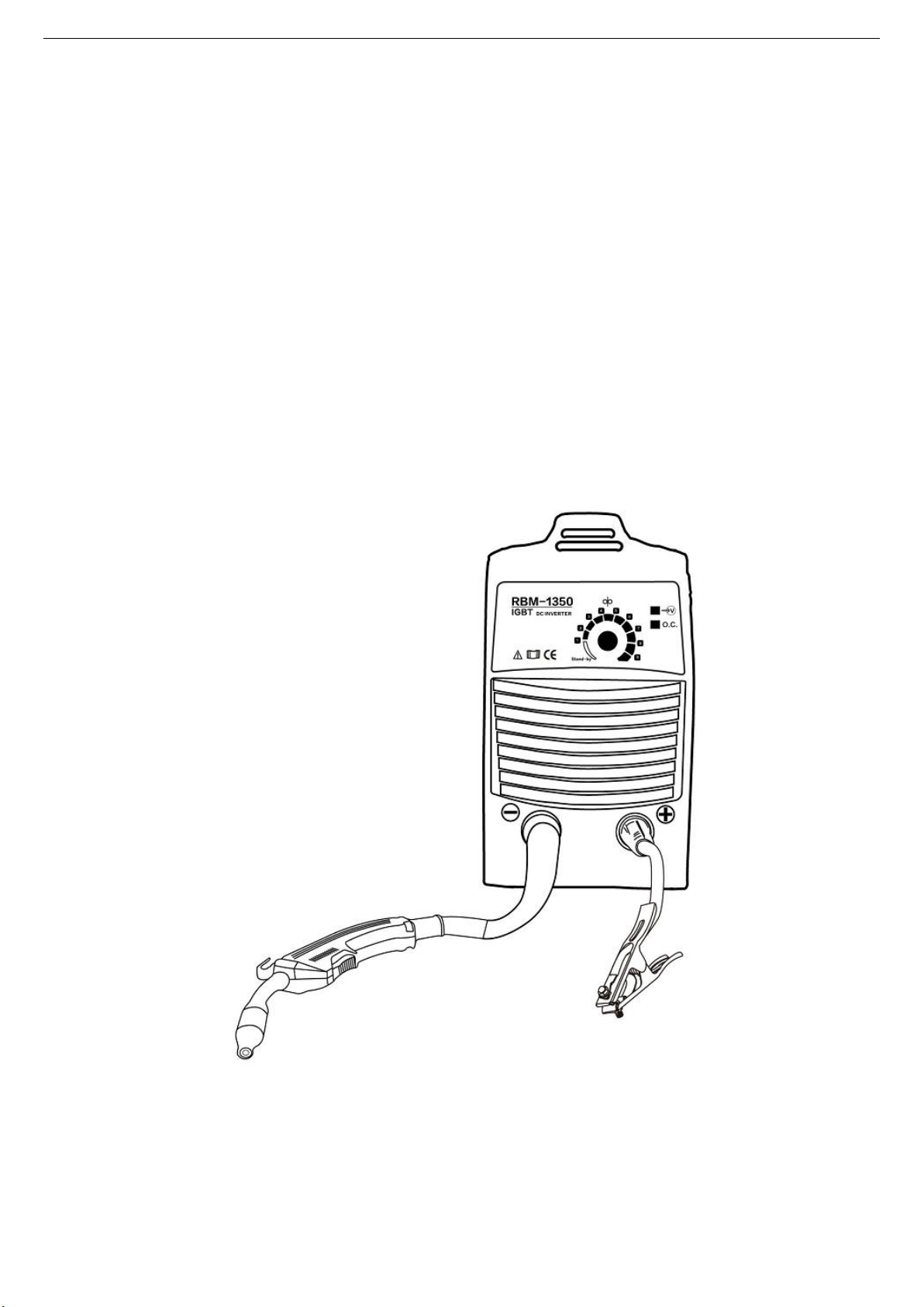
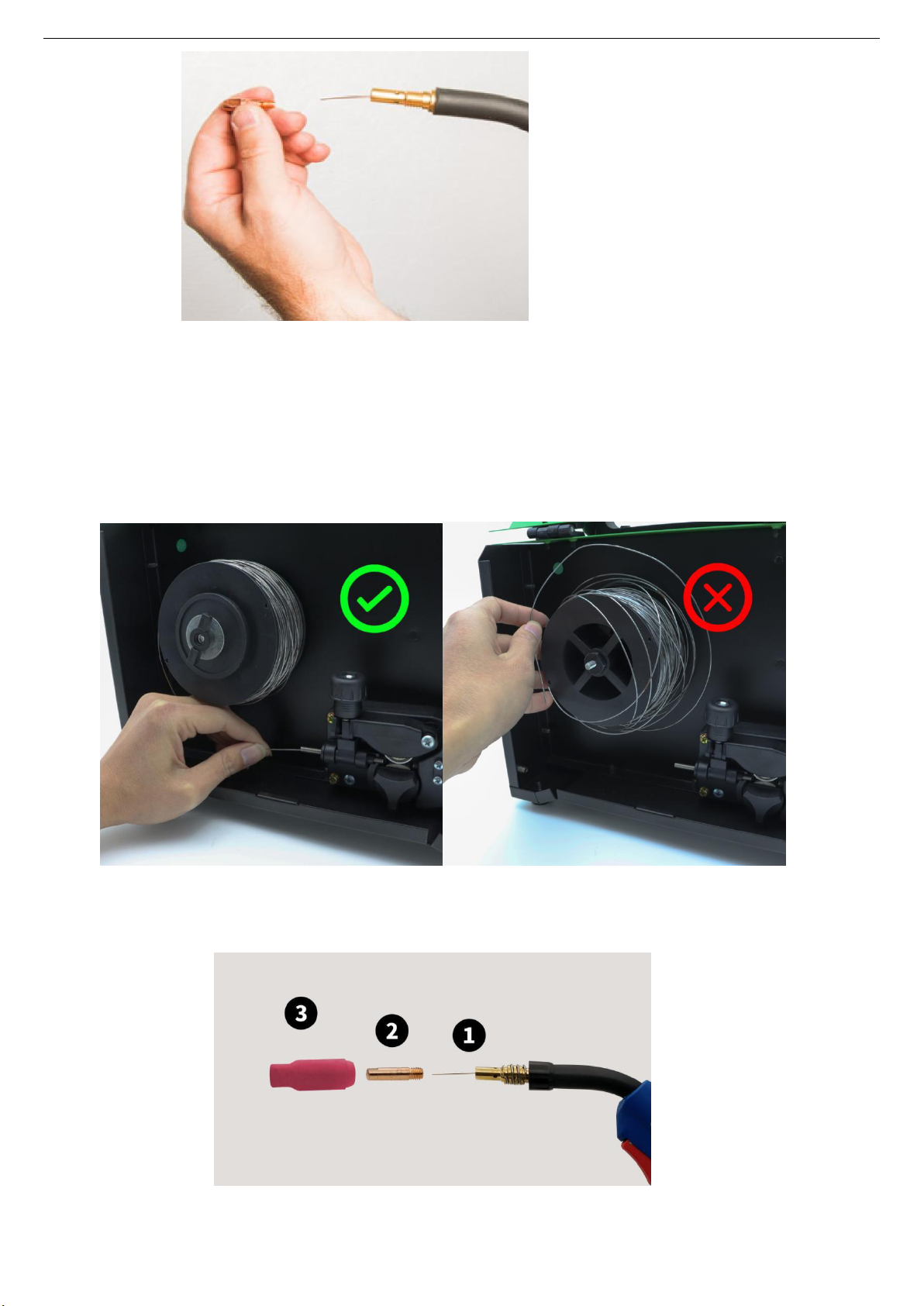
1) Please strictly follow the picture instructions to connect, otherwise it will not be possible to solder.
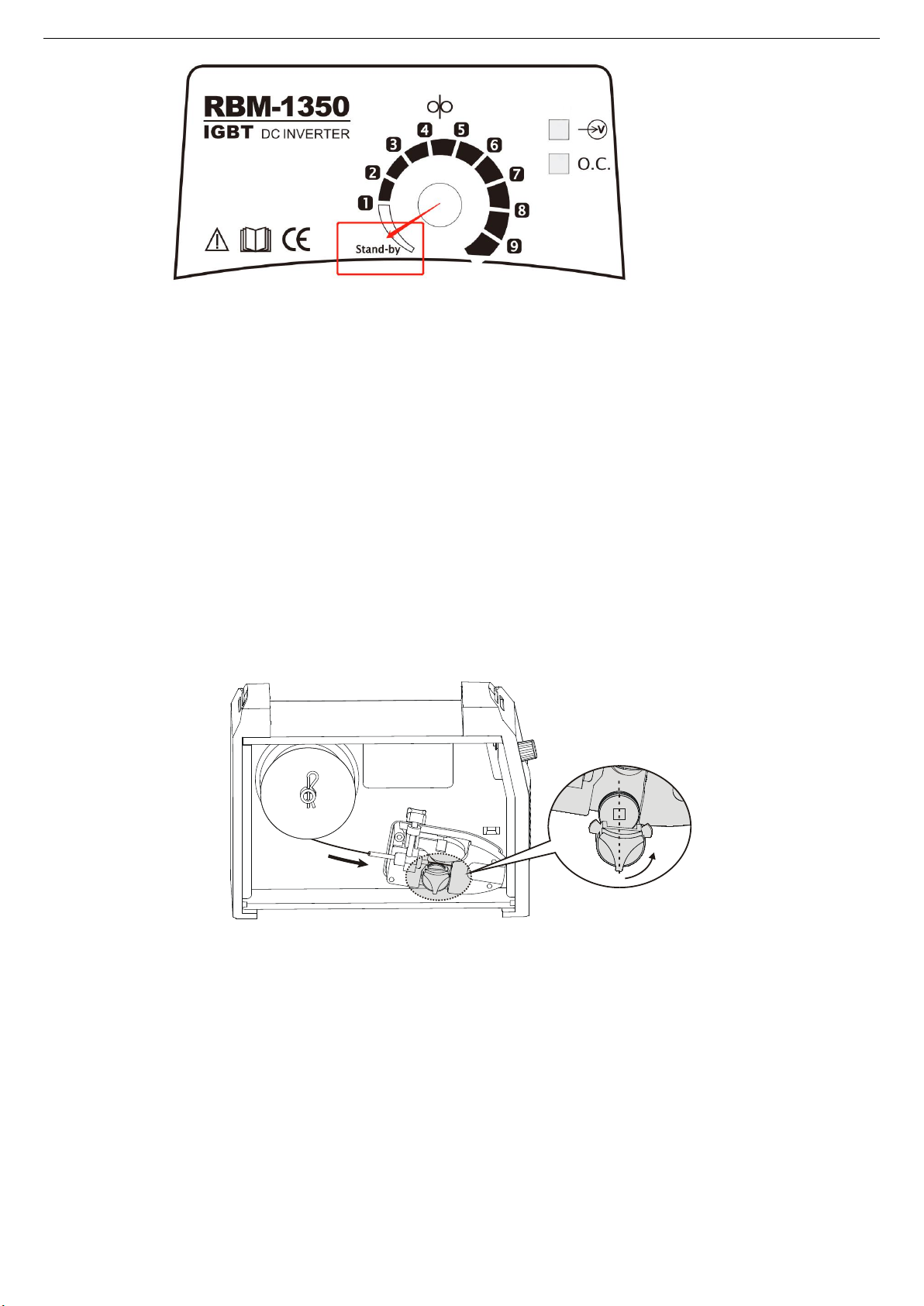
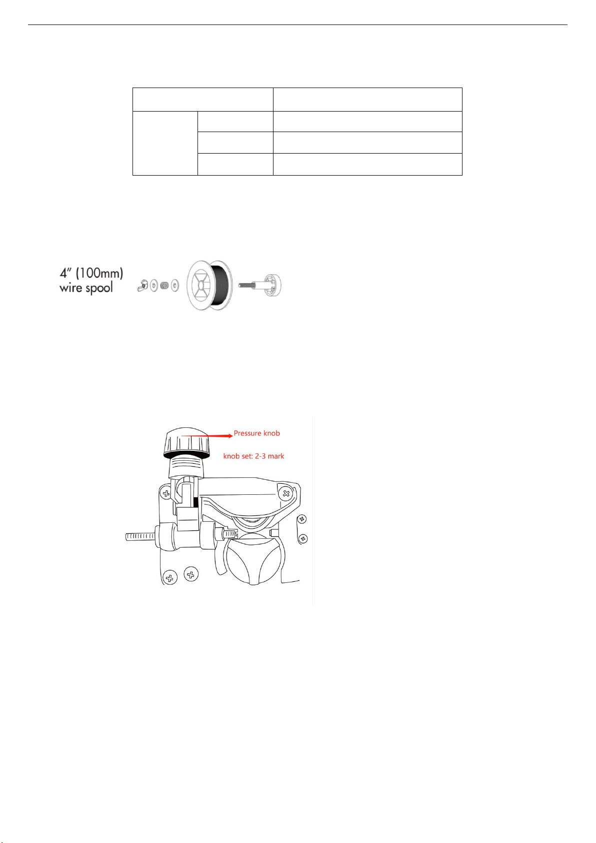
2) The flux-cored welding wire supports 0.8mm, 0.9mm.
3) The machine can install 1kg(2.2lb) welding wire reels.
4) The machine is equipped with a 1kg(2.2lb) flux cored wire, which can be directly installed and used.
5) Support welding material: carbon steel(Note: Aluminum and stainless steel cannot be welded.)
6) The diameter of the welding wire, the groove of the wire feed wheel and the aperture of the contact tip must
match.
7) The pressure roller of the wire feeding structure should not be too tight or too loose, which will cause the
wire feeding to be unstable.
8) The installation of the wire feed reel should not be too loose or too tight, which will cause the welding wire of
the wire reel to spring off and the wire feeding too slow.
Possible problems
1) There is no response when turning on the power, please check the plug connection.
2) There is no response when turning on the power, please open the cover and check whether the internal
connecting wires are loose.
3) The wire feeding is unstable. Please check the wire feeding reel and the wire feeding pressure roller, and the
welding gun should not be wound. Pay attention that the diameter of the welding wire matches the wire
feeding wheel groove and contact tip.
4) No wire feeding, please confirm that the welding gun is connected well, press the gun switch or no wire
feeding, please contact us.
5) During the welding process, if the time exceeds 3 minutes, over-current protection may occur. You need to
stop working for a few minutes, let the machine cool for a period of time, and automatically recover. If the air
cools for more than 10 minutes, the machine does not automatically recover, please shut down and restart.
6) If you have any questions, please contact us .
3.10 Welding environment and safety
Working surrounding
a) Welding should be carried out in dry surroundings. The air humidity level should not be higher than 90%.
b) The temperature should be between -10C to 40C.
c) Don’t use the welding machines in sunshine or rain. Keep it off water.
d) Don't use the machines in the places of dust or corrosive air.
Safety norms
Protection circuit of over-voltage, over-current and over-heat circuits are designed in the welding machines.
It will stop working automatically when the input voltage, output current or internal temperature exceed the
rated value. But if the machines are excessively used, such as with input voltage higher than the rated, the
machine might be damage. Please pay close attention to the following matters.
a) Keep good ventilation!
The welding machines work with high welding current. Nature air flow can’t reach the requirement of heat
dissipation. So the fans are installed as cooling system to ensure stable performance.
Make sure the ventilation windows are not covered or blocked. The distance between the machines and

Version Number: RBM-1350 20210712A2
11
things around should not be less than 0.3m. Good ventilation is good for welding performance and
operational life.
b) Never over load!
Check the maximum rated current (according to the Duty Cycle chosen). Make sure the welding current is
never higher than the rated value. Over current running will obviously shorten the operation life, even
damage the machine .
c) Never over voltage!
The Input Voltage could be found in Technical data diagram. The auto-compensation function will keep the
welding current in the rated range. If the input voltage exceed the permissible value, the machine would be
damaged. Users should take protective measures in advance to avoid it.
d) Never cut off the power supply arbitrarily.
When the operating time is longer than the duty cycle, the machine may enter the status of protection
suddenly and stop working, for excessive heat triggering the temperature-sensing switch. Meanwhile, the
red light in the front panel will be on. Under such conditions, don’t cut off the power supply so the fans can
make the machines cool. When the red light is off, the machines will be ready for welding again as the
temperature falls into the rated rage again.
3.11 Welding problems and resolution
The phenomenon listed below may happen due to relevant accessories used, welding material, surroundings
and power supply. Pleas improve surroundings and avoid these problems.
Arc starting difficulty. Arc interruption happens easily.
a) Examine whether grounding wire clamp contacts with the work pieces well.
b) Examine whether each joint has improper contact.
The output current fails to reach rated value.
The deviation of power voltage from rated value may cause that the output current does no accord with
adjusted value. When the power voltage is lower than rated value, the maximum output current may be
lower than rated value.
The current can not keep stable during operation.
This situation may relate to the following factors:
a) The voltage of electric power network changes;
b) Serious interference from electric power network or other electric facilities

Version Number: RBM-1350 20210712A2
12
Part 6 Daily maintenance and checking
Daily maintenance
a) Remove dust regularly with dry compressed air. If the welding machine is used in surroundings with heavy
smoke and polluted air, it is necessary to remove dust at least one time one month.
b) Examine inside electric joints and ensure perfect contact (Especially plugs and sockets). Fasten the loosing
joints. In case of oxidation, remove oxide film with sand paper and connect again.
c) Prevent water from entering into the machine and prevent the machine from getting moist. If any, blow and
dry. Measure the insulation with megohmmeter to make sure it is qualified to use.
d) If the welding machine is not used for a long time, pack the machine in original package and store in dry
surroundings.
e) Every time the wire feeder operates for 300hours, grind the electrical carbon brush and clear up the
armature commutator. Rinse speed reducer, apply 2# Molybdenum Disulfide lubricant to the turbine,
whirlpool rod and bearing.
All the maintenance and testing must be carried out when the power supply is totally cut off. Please
make sure the power is off before opening the closure.
Daily checking
WELDING TORCH
Position
Checking keys
Remarks
Loophole
If installment fixed, the front distorted
Reason for air hole.
Attach splash or not.
Reason for burning the torch.
(can use splash-proof material )
Electric
hole
If installment fixed
Reason of torch screw thread damage
Damage of its head and hole blocked
nor not
Reason of unstable arc and broken arc
Wire
sending
tube
Check the extended size of the pipe
Have to be changed when less than 6mm,
when the extended part too small, the arc will
be unstable.
Wire diameter and the tube inner
diameter match or not
Reason of unstable arc, please use the
suitable tube.
Partial winding and extended
Reason of poor wires sending and unstable
arc, please change.
Block caused by dirt in the tube, and
the remains of the wire plating lay.
Reason of poor wire sending and unstable arc,
(use kerosene to wipe or change new one.)
Wire sending tube broken O circle
wear out
1.Pyrocondensation tube broken, change new
tube
2.Change new O circle

Version Number: RBM-1350 20210712A2
13
CABLE
Position
Checking keys
Remarks
Torch
cable
If torch cable over bended.
If the metal connecting point of
mobile plug loosen.
Cause poor wire sending.
Unstable arc if cable over bended.
Output
cable
Wearing-out of the cable insulated
material.
Cable connecting head
naked(insulation damage),or
loosen(the end of power supply, and
cable of main material connecting
point.)
For life security and stable welding, adopt
suitable method to check according to
working place.
Simple check daily
Careful and in-depth check on fixed period
Input
cable
If the connect of power supply input,
protective equipment input and the
output end fixed or not.
If the security equipment cable
reliably connected.
If the power input end cable fixed.
If the input cable is worn out and
bares the conductor.
Earth
cable
If the earth cable that connects the
power supply is broken and connect
tightly.
If the earth cable that connects the
main part is broken and connects
tightly.
To prevent creep age and insure security,
please make daily check.

Version Number: RBM-1350 20210712A2
14
Part 7: Trouble shooting and fault finding
Notes. The following operations must be performed by qualified electricians with valid certifications. Before
maintenance, you are suggested to contact local distributor to verify qualification.
Fault symptom
Remedy
Power indicator is
not lit, fan does not
work and no
welding output
1. Make sure air switch is closed.
2. Check if electric wire net is in work.
3. Some of heat-variable resistors(four) of power panel is damaged,
when it happen, general DC14V relay is open or connectors are poor
contact.
4. Power panel (bottom board) is damaged, DC 130V voltage cannot be
output.
(1) Silicon bridge is broken or connector of silicon bridge poor contact.
(2) Power panel has been burned up.
(3) Check contact and insert cable from air switch to power panel are
poor contact, check contact and insert cable from power panel to
IGBT board are connected reliably.
5. Auxiliary power of control panel is in fault.
Power indicator is
lit, fan works, no
welding output
1. Check if all kinds of cables of inter-machine are poor contact.
2. Output connector is cut off
3. Output connector is cut off or poor contacted.
4. Control circuit is broken.
Power indicator is
lit, fan works,
abnormal indicator
is lit.
1. Maybe it is overheated protection, please turn off machine first, then
turn on the machine again after abnormal indicator is off.
2. Maybe it is overheated protection, wait for 2-3 minutes.
3. Maybe inverter circuit is in fault, please pull up the supply power plug of
main transformer which is on IGBT board then open the machine
again:
1) If abnormal indicator is still lit, some of fieldistor of IGBT board
are damaged, find out and replace them with same model.
2) If abnormal indicator is not lit:
a.Maybe transformer of middle board is damaged, measure
inductance volume and Q volume of main transformer by
inductance bridge. If volume is too low, please replace it.
b.Maybe secondary rectifier tube of transformer is damaged,
find out faults and replace rectifier tube with it.
The power supply box must be cut off before checking for security. Or serious accident like electric
shock or burning would be caused.

Version Number: RBM-1350 20210712A2
15
Part 8: Welding parameter settings
RBM1350(MIG135E) machine welding parameters
Material
Wire
Type
Shielding
Gas
20-30
SCFH
Polarity
Setting
Wire
Size
Settings
MIG135E
RBM1350
Material Thickness-110V
Material Thickness-220V
24 Ga.
0.6mm
20 Ga.
0.9mm
18
Ga.
1.2m
m
16
Ga.
1.6m
m
14 Ga.
2.0mm
24 Ga.
0.6mm
20 Ga.
0.9mm
18 Ga.
1.2mm
16 Ga.
1.6mm
14 Ga.
2.0mm
Mild
Steel
Solid
Wire
ER70S-6
C25
75% Ar
25% CO2
DCEP
0.025"
0.6m
m
Wire
speed
Voltage
Inductance
90
14
3-5
110
14.5
3-5
145
16.5
3-5
190
17
3-5
260
18
3-5
90
14
3-5
110
14.5
3-5
145
16.5
3-5
190
17
3-5
260
18
3-5
0.030"
0.8m
m
Wire
speed
Voltage
Inductance
-
80
15
5-10
105
16
5-10
135
16
5-10
165
17
5-10
-
80
15
5-10
105
15.5
5-10
135
16
5-10
165
17
5-10
0.040"
1.0m
m
Wire
speed
Voltage
Inductance
-
80
14
5-10
100
16
5-10
125
17
5-10
160
17.5
5-10
-
80
14
5-10
100
16
5-10
125
17
5-10
160
17.5
5-10
C100
100%
CO2
DCEP
0.025"
0.6m
m
Wire
speed
Voltage
Inductance
105
14
1-3
110
15
1-3
150
17.5
1-3
190
19
1-3
220
19
1-3
105
14
1-3
110
15
1-3
150
17.5
1-3
190
17
1-3
220
19
1-3
0.030"
0.8m
m
Wire
speed
Voltage
Inductance
-
80
16
3-6
120
16.5
3-6
130
17.5
3-6
170
17.5
3-6
-
80
16
3-6
120
16.5
3-6
130
17.5
3-6
170
17.5
3-6
0.040"
1.0m
m
Wire
speed
Voltage
Inductance
-
-
120
17
3-6
140
17.5
3-6
170
18.5
3-6
-
-
120
17
3-6
140
17.5
3-6
170
18.5
3-6
Flux-Cor
ed
E71T-11
None
DCEN
0.030"
0.8m
m
Wire
speed
Voltage
Inductance
-
80
13
5-10
80
13.5
5-10
95
14.5
5-10
135
16
5-10
-
80
13
5-10
80
13.5
5-10
95
14.5
5-10
135
16
5-10
0.040"
1.0m
m
Wire
speed
Voltage
Inductance
-
-
80
14
5-10
80
14.5
5-10
110
15.5
5-10
-
-
80
14
5-10
80
14.5
5-10
110
15.5
5-10
Stainless
Steel
ER308L
Tri-Mix
90% He
7.5% Ar
DCEP
0.040"
1.0m
m
Wire
speed
Voltage
-
90
18
5-10
100
18.5
5-10
120
18.5
5-10
145
19
5-10
-
90
18
5-10
100
18.5
5-10
120
18.5
5-10
145
19
5-10

Version Number: RBM-1350 20210712A2
16
2.5% CO2
Inductance
This manual suits for next models
1
Table of contents
Other Reboot Welding System manuals
Popular Welding System manuals by other brands

ESAB
ESAB heliarc 160i Operator's manual

Cebora
Cebora Plasma PROF 166 HQC instruction manual

Abicor Binzel
Abicor Binzel xFUME TIG operating instructions

Demiriz
Demiriz Spot ALU manual

Lincoln Electric
Lincoln Electric COMMANDER 300 IM700-D Operator's manual

Lincoln Electric
Lincoln Electric SPEEDTEC 200C BR Operator's manual

Smarter
Smarter MIG-130 instruction manual

SWF
SWF ACE - P100 Operator's manual

Lincoln Electric
Lincoln Electric ASPECT 375 Specification sheet

OTC DAIHEN EUROPE
OTC DAIHEN EUROPE DTX 2500 manual

Thermal Dynamics
Thermal Dynamics CUTMASTER 151 operating manual

Campbell Hausfeld
Campbell Hausfeld Welder/Generator operating instructions