Reboot RBT-200PD/ACDC User manual

Version Number: RBT200P/ACDC-20210702A2
1
Operation Manual
Reboot RBT-200PD/ACDC welding machines adopts the latest pulse width modulation (PWM) technology
and insulated gate bipolar transistor (IGBT) power module, which can change work frequency to medium frequency
so as to replace the traditional Transistor transformer with the medium frequency transformer. its characterized with
portable, small size, light weight, low consumption and etc. It is also an intelligent and easy-to-operate multi-function
welding machine with MMA, DC TIG, AC TIG . It has the characteristics of strong welding performance and
diversified usage scenarios. Especially for welded aluminum and stainless steel,, and the welding effect is excellent.
It is highly praised by welding enthusiasts. It is also very friendly to beginners in welding and can quickly get started.
Part 1: Machine Introduction
1. Current display meter
The digital Ammeter is used to display the actual output current of the power source.
It is also used to display Parameters in Programming Mode.
Depending on the Programming Parameter selected, the status indictor adjacent to the Ammeter will
illuminate to show the units of the programming parameter.
When welding, the Ammeter will display actual welding current.
2. 2T/4T Mode selection
3. MMA/TIG Function selection
4. Function selection and digital adjustment.
Press once to select the function, and rotate to adjust the value.

Version Number: RBT200P/ACDC-20210702A2
2
5. AC/DC Mode selection
6. Positive Terminal
Positive Terminal. Welding current flows from the power source via heavy duty bayonet type terminals. It is
essential, however,that the male plug is inserted and turned securely to achieve a sound electrical
connection..
7. Gas connector.
Reliably connects with the connector of the TIG welding gun and plasma cutting gun.
8. Five core aviation socket
Tig gun switch control line connection, cutting gun switch control line connection and remote control foot
switch control line connection.
9. Negative Terminal
Negative Terminal. Reliably connects with the electrode holder / TIG welding gun and plasma cutting gun.
Part 2: Introduction to the product and configuration list
No.
Picture
Name
Qty
Remark
1
RBT-200PD/ACDC
1
Please check whether there are
scratches and breaks on the
outside of the whole machine,
and it can be started normally.
2
WP-17 Welding gun
1
4m WP-17 gun, 10-25
European style quick plug,
Trafimet quick plug, five-core
aviation plug.
3
Welding holder
1
3 meters 16MM2, 200A Italian
welding tongs +10-25
European quick plug
4
Ground wire pliers
1
3 meters, 16MM2, 300A
ground wire pliers + 10-25
European quick plug
5
Conversion line
1
Conversion line only suit for
220V to 110V dual-voltage
input machines, if not dual-
voltage machines no this line
included.

Version Number: RBT200P/ACDC-20210702A2
3
6
Gas tube
1
3m 8*12 transparent network
management.
7
Hose clamp
2
Used to fix the trachea to
prevent air leakage.
8
Collect body
3
Vulnerable parts, need to be
replaced frequently, please
prepare the goods
9
Collect
3
Vulnerable parts, need to be
replaced frequently, please
prepare the goods
10
Nozzle
3
Vulnerable parts, need to be
replaced frequently, please
prepare the goods
13
Manual
1
Normally provides manuals in
English, if you need other
language like French,
German, Italian, Spanish, and
Russian please contact us to
get electronic version
documents.
Part 3: Simple test for powering on the machine
Reboot RBT-200PD/ACDC Welding machines will be subjected to strict various tests when they leave the
factory to ensure that each welding machine that reaches the user is of high quality, because our machine has to go
through tens of thousands of kilometers of long-distance transportation from the factory to the delivery to you. It’s
inevitable that some uncontrollable factors will cause some internal components of the machine to become loose or
even damaged in the process. We recommend that you check the external device as soon as you get the welder, and
turn on the power to check to ensure that you receive It is a qualified product.
Precautions for power-on inspection:
1、Please make sure your power supply voltage is 110V+-15% or 220+-15%. REBOOT RBT-200P ACDC
supports 110V and 220V input voltage in North America and Japan; if you have a generator power supply,
please ensure that the generator is not less than 5000w..
2、It is recommended to choose 60A circuit breaker protection when your power supply voltage is 110V, and

Version Number: RBT200P/ACDC-20210702A2
4
30A circuit breaker protection when 220V..
3、Please choose the power plug that suits your local electrical law requirements.
4、Extension cord: #12 AWG or larger; 25’ (8m) or shorter.
Turn on the power switch of the machine and the fan on the back of the machine rotates, and the digital
display on the panel indicates that the power is normal.
Note:
1) The digital display shows irregular changes at the beginning, and then returns to the digital display after 3
seconds, which is normal.
2) In order to reduce the working temperature of the machine, it is normal for the fan to continue to rotate for a
few seconds after the power is turned off.
3) During high-strength continuous welding, machine protection may occur. After continuous heat dissipation,
the machine will return to normal, which is normal.
Attached table: Self-examination of abnormal conditions without response when turning on the machine:
1. The machine's power switch is not turned on.
2. The power input voltage is wrong.
3. The power plug is loose.
4. The internal circuit is loose (due to long-distance transportation, bumps), you need to open the cover and
check the internal connection line.
Part 4: Technical specifications
Description
RBT-200PD/ACDC
Weight
12 kg
Power Source Dimensions
L470mmxW155mmxH300mm
Fan Cooled
Cooling
Welder Type
Inverter Power Source
European Standards
EN 60974-1 / IEC 60974-1
Number of Phases
1
Nominal Supply Voltage
110V-220V ±15%
Nominal Supply Frequency
50/60Hz
Welding Current Range (MMA Mode)
AC110V:10-120A
AC220V:10-170A
Welding Current Range (TIG Mode)
AC110V:10-130A
AC220V:10-200A
Maximum Input Current
AC110V:I1max 47A
AC220V:I1max 31A
Effective Input Current
AC110V:I1eff 30A

Version Number: RBT200P/ACDC-20210702A2
5
AC220V:I1eff 19A
Single Phase Generator Requirement
10KVA
Duty cycle, 40ºC, 10 min (MMA)
AC110V:120A @ 35%, 25V
71A @ 100%, 23V
AC220V:170A @ 40%, 26.8V
108A @ 100%, 24.3V
Duty cycle, 40ºC, 10 min (TIG)
AC110V:130A @ 35%, 15.2V
77A @ 100%, 13V
AC220V:200A @ 40%, 18V
126A @ 100%, 15V
Open circuit voltage
(MMA/60V,TIG/60V)DC
Protection Class
IP23
Insulation Class
H
Part 5: Machine operation guidance.
Tips:
1. Wear a welding helmet fitted with a proper shade of filter to protect your face and eyes when welding or
watching;
2. Wear approved safety glasses. Side shields recommended;
3. Use protective screens or barriers to protect others from flash and glare; warn others not to watch the arc;
4. Wear protective clothing made from durable, flame-resistant material(wool and leather) and foot
protection;
5. Use approved ear plugs or ear muffs if noise level is high;
6. Never wear contact lenses while welding.
1、MMA mode
If you want to repair some broken fences or fix brackets, you like to use traditional welding rods for operation,
you can use Reboot RBT-200PD/ACDC MMA mode for welding.

Version Number: RBT200P/ACDC-20210702A2
6
1.1 Select “MMA” process.
1.2 Connect welding holder and ground clamp.

Version Number: RBT200P/ACDC-20210702A2
7
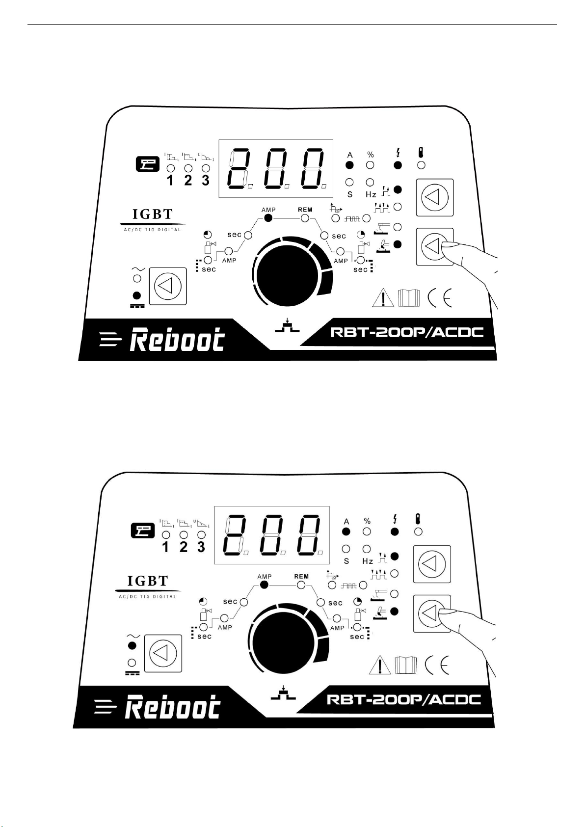
1.3 To adjust the current, only the current can be adjusted.
1. Hot Start Function reliably ignites the electrode and melts perfectly to ensure the best quality
even at the start of the seam. this solution makes lack of fusion and cold welds a thing of the past
and significantly reduces weld reinforcement. Adjust the hot start current here and the time here.
2. Arcforce Correction During the welding process, arcforce prevents the electrode sticking in the weld pool with
increases in current. this makes it easier to weld large-drop melting electrode types at low current strengths with
a short arc in particular
3. Anti-stick prevents the electrode from annealing. If the electrode sticks in spite of the arcrorce device, the
machine automatically switches over to the minimum current within about 1 second to prevent the electrode
from overheating. In order to easily separate the electrode and electrode holder to protect the welder.
Note:
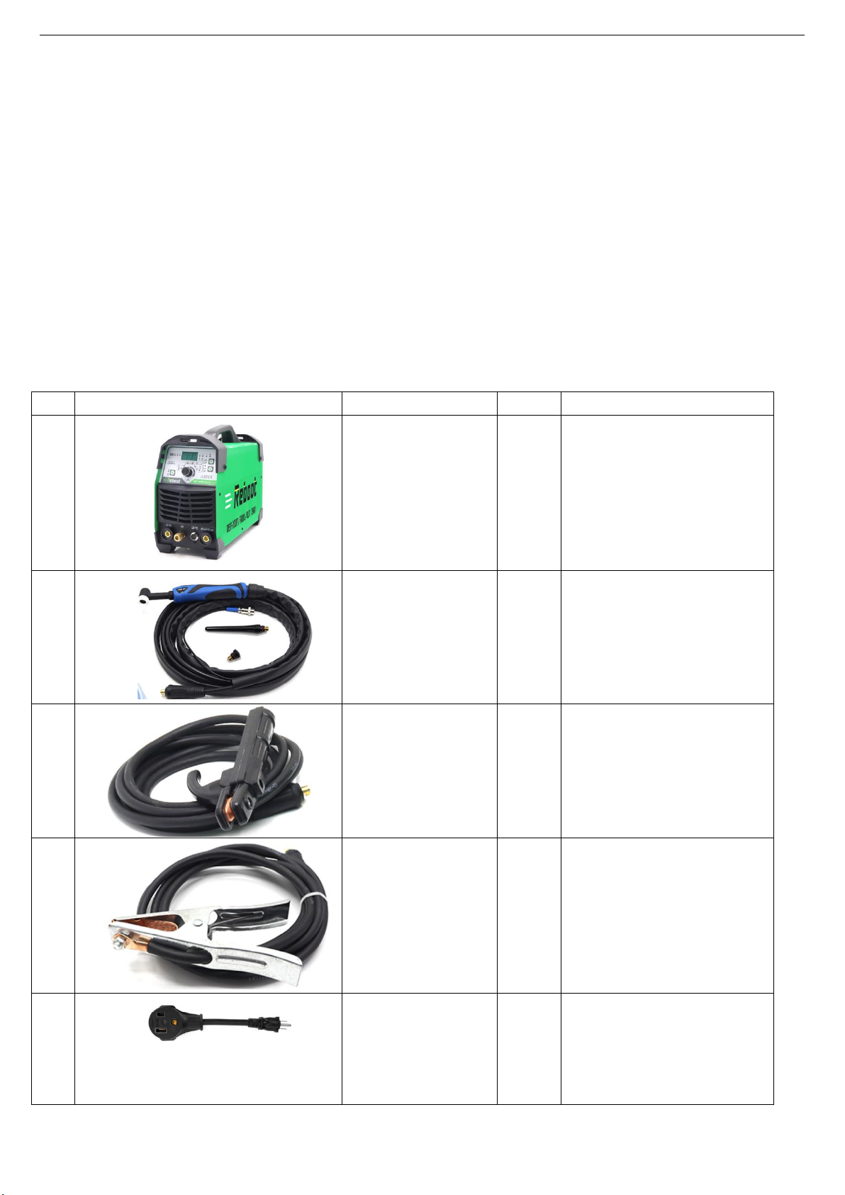
1) The welding rod specification supported by Reboot RBT-200PD/ACDC is below 4.0(5/32in), usually 2.5(3/32in)
and 3.2(1/8in). European style generally uses E6013, American style generally uses E7018, and stainless
steel generally uses ER308.
2) It supports welding of 1-8mm(1/64-5/64in) carbon steel and 1-5mm(1/64-7/32in) stainless steel. Aluminum
can not be welded. For carbon steel, please use carbon steel electrode. For stainless steel, please use
stainless steel electrode.
3) Connect the ground clamp to clean bare metal. No rust, paint or other coatings, and ensure good electrical
conductivity.
4) The ideal distance between the welding rod and the welding object is 1-2mm(1/64-5/64in), to ensure that the
welding rod and the workpiece are in continuous and stable contact. The welding rod should not be too high
or pressed too low to avoid arc breaking and adhesion.
5) It is normal for novices to have adhesion during the welding process, and you can try to friction arc to avoid
adhesion.
6) Suitable for ordinary welding rods, such as 7018, 6013, etc., but not suitable for special welding rods, such as
7010, 7011.
Possible problems
1) There is no arc, check the ground wire to connect the workpiece to ensure that there is no rust, paint or other
coatings on the workpiece.

Version Number: RBT200P/ACDC-20210702A2
8
2) There is no arc, check the direct distance between the welding rod and the welding object, the ideal distance
is 1-2 mm; check whether the welding object has rust or oil stains, it is recommended to polish with sandpaper
or a grinder.
3) When welding, the spatter is very big, and it feels very difficult to weld. Please try to change the polarity
connection of the ground wire clamp and the welding clamp with the machine.
4) During the welding process, if the time exceeds 3 minutes, overcurrent protection may occur. You need to stop
working for a few minutes, let the machine cool down for a period of time, and automatically recover. If the air
cools for more than 10 minutes, the machine does not automatically recover, please shut down and restart.
5) If you have any problems that cannot be solved, please contact us .
2、TIG mode.
Reboot RBT-200PD/ACDC requires higher welding process for thin plates or welding with higher
process requirements, especially for the welding of stainless steel and aluminum. TIG/ACDC mode
can be used. In this mode, pure AR gas is required.
2.1 Select “ TIG ” process.
2.2 Connect Tig gun and ground clamp.

Version Number: RBT200P/ACDC-20210702A2
9
2.3 Connect the foot controller
1. This will light up when the foot controller is connected.
2. Connect the foot switch control wire.
2.4 Connect compressed air.
Note: Please refer to the digital sign on the rear panel of the machine for the input voltage, the wrong voltage will
damage the machine.

Version Number: RBT200P/ACDC-20210702A2
10
2.5 TIG DC mode.
Mainly welding carbon steel and stainless steel, long welding and spot welding are possible.
2.6 TIG AC mode
Mainly weld aluminum.

Version Number: RBT200P/ACDC-20210702A2
11
2.7 Parameter adjustment.
1. Gas Pre-Flow
Absolute setting range 0.1s to 5s (0.1S increments)
This parameter operates in TIG modes only and is used to provide gas to the weld zone prior to striking the arc, once
the torch trigger switch has been pressed. This control is used to dramatically reduce weld porosity at the start of a
weld.
2. Initial Current
The main current Setting range 10AMP to 200AMP
This parameter operates in TIG modes and is used to set the starting current of TIG. The Start Current remains on until
the torch trigger switch is released after it has been depressed. (Can be set in 2T or 4T mode.)
Note: The maximum initial current available will be limited to the set value of the base.
3. Up Slope
Setting ranges :0.1S-10S (0.1S increments)
This parameter operates in TIG modes only and is used to set the time for the weld current to ramp up, after the torch
trigger switch has been pressed then released, from Initial Current to High or base current. (Can be set in 2T or 4T
mode.)
4. Peak Current
Setting ranges
10AMP to 200AMP (DC TIG and AC HF TIG mode), 10 to 170A (STICK mode) This parameter sets the TIG WELD
current. This parameter also sets the STICK weld current.
5. Remote Control
The system independently identifies the remote control, and when the indicator light is on, the welding current can be
adjusted by remote (foot or welding gun).
6. Down Slope
Setting ranges 0.1-10s
This parameter operates in TIG modes only and is used to set the time for the weld current to ramp down, after the
torch trigger switch has been pressed to end current. This control is used to eliminate the crater that can form at the
completion of a weld.
7. End current

Version Number: RBT200P/ACDC-20210702A2
12
Setting ranges 10A-200A
This parameter operates in TIG modes only and is used to set the finish current for TIG. The end Current remains ON
until the torch trigger switch is released after it has been depressed. (Can be set in 2T or 4T mode.)
Note: The maximum crater current available will be limited to the set value of the base current.
8. Post Flow
Setting ranges 1-10S
This parameter operates in TIG modes only and is used to adjust the post gas flow time once the arc has extinguished.
This control is used to dramatically reduce oxidation of the tungsten electrode.
9. Wave Balance
Setting arranges 10%-30%
This parameter operates in AC TIG mode and is used to set the penetration to cleaning action ratio for the AC weld
current. Generally WAVE BALANCE is set to 30% for AC STICK welding. The WAVE BALANCE control changes the
ratio of penetration to cleaning action of the AC TIG welding arc. Maximum weld penetration is achieved when the
WAVE BALANCE control is set to 10%. Maximum cleaning of heavily oxidised aluminium or magnesium alloys is
achieved when the WAVE BALANCE control is set to 30%
AC Balance Control
Controls arc cleaning action. Adjusting the % EN of the AC wave controls the width of the etching zone surrounding the
weld.
Note: Set the AC Balance control for adequate arc cleaning action at the sides and in front of the weld puddle. AC
Balance should be fine tuned according to how heavy or thick the oxides are.
Wider bead, good penetration Narrower Bead, Good Penetration
ideal for buildup work Ideal For Buildup Work
Wider bead and cleaning action Narrower bead, with no visible cleaning
10. AC Frequency
Setting ranges 50HZ-200HZ

Version Number: RBT200P/ACDC-20210702A2
13
This parameter operates in AC TIG mode only and is used to set the frequency for the AC weld current.
AC Frequency control
Controls the width of the arc cone. Increasing the AC frequency provides a more focused arc with increased directional
control.
Note: Decreasing the AC Frequency softens the arc and broadens the weld puddle for a wider weld bead.
Wider bead, good penetration Narrower bead for fillet welds and
ideal for buildup work automated applications
Wider bead and cleaning acting Narrower bead and cleaning acting
2.8 TIG Basic Welding Technique
Gas Tungsten Arc Welding (GTAW) or TIG (Tungsten Inert Gas) as it is commonly referred to, is a welding
process in which fusion is produced by an electric arc that is established between a single tungsten (non-
consumable) electrode and the work piece. Shielding is obtained from a welding grade shielding gas or welding
grade shielding gas mixture which is generally Argon based. A filler metal may also be added manually in some
Circumstances depending on the welding application.

Version Number: RBT200P/ACDC-20210702A2
14
1. Welds Made With or Without
Addition of Filler Metal.
2. Work Piece can be any commercial
metal.
3. Gas Cup Either Ceramic,High-lmpact or
Water Cooled Metal.
4. Tungsten Electrode Non-Consumable.
5. Inert Gas Shields Electrode and Weld
Puddle.
TIG Welding Application Shot
2.9 WP17 The structure of the welding gun
Rmark: 1. ceramic nozzel, 2 .tungsten collet, 3. tungsten collet body, 4 .short back cap, 5. long back cap.
The above structure is a wearing part, please keep it in stock.
Note:
1) Please connect according to the picture, otherwise it cannot be welded
2) Support welding material, carbon steel, stainless steel, alloy steel, aluminum can not be welded.
3) This welding mode requires the use of tungsten needles, which need to be purchased separately, and the size
of the tungsten needle must match the collet and collet body of the welding gun, otherwise it cannot be
installed
4) In this mode, argon welding must be used.
possible problems
1) There is no response when starting up, please check the plug connection.
2) There is no response when booting up, please open the cover and check whether the internal connection

Version Number: RBT200P/ACDC-20210702A2
15
wires are loose.
3) During the welding process, if the time exceeds 3 minutes, over-current protection may occur. You need to
stop working for a few minutes, let the machine cool for a period of time, and automatically recover. If the air
cools for more than 10 minutes, the machine does not automatically recover, please shut down and restart.
4) If you have any questions, please contact us .
5)Lift tig is different from professional high-frequency tig. Lift tig needs to be welded after contact with arcing.
High-frequency tig does not require contact with arcing. Lift tig is not suitable for spot welding.
Part 6: Internal diagram of the machine

Version Number: RBT200P/ACDC-20210702A2
16

Version Number: RBT200P/ACDC-20210702A2
17
Part 7: Troubleshooting
Nr.
Troubles
Reasons
Solution
1
Turn on the power source,
power indicator is lit, fan is
not working.
Fan is broken
Change fan
There is something in the fan
Change it
The start capacitor of fan damaged
Change capacitor
2
Turn on the power source,
fan is working, power
indicator
is not lit
The power light damaged or
connection is not good
Change the power light
The power board is broken
Change it
Display panel is broken
Change it
3
Turn on the power source,
power indicator is lit, fan
is working, there is no
welding
output.
Control board is broken
Change it
1 inverter circuit damaged st
Replace it
2 feedback circuit is fault nd
Change it
4
Turn on the power source,
fan is not working, power
indicator is not lit
The power cable connected not good
Connect correctly
The power cable is broken
Repair or change it
Power on switch is damaged
Change it
The light of the power indicator is
broken and the problems
mentioned in Nr. 2
Change the light of the power
indicator or refer to the solution
in Nr. 2
The power board is broken
Change it
5
The number of the display is
not intact
The display panel is damaged
Change the display panel
Digital tube is broken
Change it
6
No no-load voltage output
(MMA)
If the overheat indicator is on
Wait a few minutes, the
machine can be operated
normal
The main circuit is broken
Check and repair
The machine is broken
Consult the dealer or the
manufacturer
7
Arc can not be ignited (TIG) ,
there is spark on the HF
igniting board
The welding cable is not connected
with the two output if the welder
Connect the welding cable to
the welder's output
The welding cable is damaged
Repair or change it
The earth cable connected unstably
Check the earth cable
The welding cable is too long
Use an appropriate welding
cable
There is oil or dust on the workpiece
Check and remove it
The distance between tungsten
electrode and workpiece is too long
Reduce the distance
(about 3mm ,less than 5mm)
There is no Argon flow or the
connection is poor
Check and reconnect
Input voltage not stable
Check the power supply

Version Number: RBT200P/ACDC-20210702A2
18
Nr.
Troubles
Reasons
Solution
8
Arc can not be ignited (TIG) ,
there is no spark on the HF
igniting board
The HF igniting board does not work
Repair or change it
The distance between discharger is
too short or too long
Adjust the distance (about
0.8mm)
The malfunction of the welding gun
switch
Check the welding torch
switch, control cable and aero
socket.
No argon gas flow or the air tube
connect not good
Check and reconnect
9
Turn on the power source,
everything is normal , but no
HF igniting
Check if the function selected MMA
Change the function to TIG
Check the HF funtion is selected
Select the HF funtion
HF board is broken
Repair or change it
Earth clamp connect not stable
Check the earth clamp
No argon gas flow or the air tube
connect not good
Check and reconnect
10
Gas always flows
Something is in the valve
Remove it
Electromagnetic valve is damaged
Change it
11
No gas flow (TIG)
Gas cylinder is close or gas
pressure is low
Open or change the gas
cylinder
Something is in the valve
Remove it
Electromagnetic valve is damaged
Change it
Air tube is brocken
Change it
Pressure too high or air regulator is
broken
Check gas
12
The welding current cannot
be adjusted
Checking if the electorde stick to
the work piece that the anti-stick
function is on
Separate the electrode and
work piece
Control board is broken
Repair or change it
Shut off the power when changing
the torch
13
The penetration
of molten pool is
not enough
The welding current is adjusted
too low
Increase the welding current
The arc is too long in the welding
process
Adjust the distance from torch
to work piece
The power cable or the welding
cable is too long
Use the suitable length from
manufacturer
AC Width adjustment is not correct
Change to suitable setting
14
Thermal overload indicator
light is on
Over-heat protection ,too much
welding current
Reduce the welding current
Over-heat protection ,working too
much time
Reduce the welding time
Over-current protection, current in
the main circuit is out of control
Check and repair main circuit
and drive board
Input voltage is too low
Check the power supply
Fan is broken
Change the fan

Version Number: RBT200P/ACDC-20210702A2
19
Nr.
Troubles
Reasons
Solution
15
Tig electrode melts when
welding
Tig torch is connected to the
positive terminal
Connect the tig torch to
negative terminal
16
Arc flutters during Tig welding
Tungsten electrode is too big for
the welding current
Select the correct size of
tungsten electrode
Check the earth clamp position on
the work piece
Adjust the position of earth
clamp
17
When Cut function is
selected ,there is HF but
cannot cutting
Check the welding circuit is correct,
for example the earth clamp is
connected to work piece
Connect the circuit correctly
Air flow is not correctly connected
Check the air flows
Machine is broken
Consult the dealer or the
manufacturer
18
No AC output
while selecting
"AC" for O251
The power board is broken
Repair or change it
The AC drive board damaged
Change it
The AC IGBT/IGBT module damage
Change it
Control board is broken
Repair or change it
19
The welding
current displayed
isn't accordant
with the actual
value
The min value displayed isn't
accordant with the actual value
Adjust potentiometer Imin on
the control board
The max value displayed isn't
accordant with the actual valu
Adjust potentiometer Imax on
the control board
Part 8: Welding parameter settings
Joint froms in TIG
A. Butt joint B. lap joint C. coner joint D. T joint
Tungsten Electrode
Tungsten
Electrode
Diameter/mm
Sharpened of
the Electrode
Diameter/mm
Angle of Cone(º)
Background
Current/a
1
0.125
12
2~15
1
0.25
20
5~30
1.6
0.5
25
8~50
1.6
0.8
30
10~70
2.4
0.8
35
12~90
2.4
1.1
45
15~150
3.2
1.1
60
20~200
4
1.5
90
20~300

Version Number: RBT200P/ACDC-20210702A2
20
TIG of stainless steel(single run welding)
Workpiece
thickness
/mm
Joint form
tungsten
electrode
diameter
/mm
welding
wire
diameter
/mm
Argon gas
flow rate/
L•min-1
welding
current
(DCEP)
Welding
speed/
cm•min-1
0.8
Butt joint
1.0
1.6
5
20~50
66
1.0
Butt joint
1.6
1.6
5
50~80
56
1.5
Butt joint
1.6
1.6
7
65~105
30
1.5
Corner joint
1.6
1.6
7
75~125
25
2.4
Butt joint
1.6
2.4
7
85~125
30
2.4
Corner joint
1.6
2.4
7
95~135
25
3.2
Butt joint
1.6
2.4
7
100~135
30
3.2
Corner joint
1.6
2.4
7
115~145
25
4.8
Butt joint
2.4
3.2
8
150~225
25
4.8
Corner joint
3.2
3.2
9
175~250
20
6.0
Butt joint
4.0
4.0
10-12
220~300
25
Notice: the above parameters originate from <<Welding Dictionary>> P150,Volume 1 of Edition 2
Parameters of piping back sealing welding for mild steel(DCEP)
Piping
diameter
Φ/mm
Tungsten
electrode
diameter/mm
Gas nozzle
diameter/mm
Welding
wire
diameter/mm
Welding
current/A
Welding
current/A
Arc
voltage/V
Argon flow
rate/L•min
1
Welding
rate/cm•min-1
38
2.0
8
2
75~90
11~13
6~8
4~5
42
2.0
8
2
75~95
11~13
6~8
4~5
60
2.0
8
2
75~100
11~13
7~9
4~5
76
2.5
8~10
2.5
80~105
14~16
8~10
4~5
108
2.5
8~10
2.5
90~110
14~16
9~11
5~6
133
2.5
8~10
2.5
90~115
14~16
10~12
5~6
159
2.5
8~10
2.5.
95~120
14~16
11~13
5~6
219
2.5
8~10
2.5
100~ 120
14~16
12~14
5~6
273
2.5
8~10
2.5
110~ 125
14~16
12~14
5~6
325
2.5
8~10
2.5
120~ 140
14~16
12~14
5~6
Notice: the above parameters originate from <<Welding Dictionary>> P167, Volume 1 of Edition 2.
Table of contents
Other Reboot Welding System manuals
Popular Welding System manuals by other brands

ESAB
ESAB OCF 2L instruction manual

Westweld
Westweld RSR-2500 Manual instruction

Lincoln Electric
Lincoln Electric RED-D-ARC GX 300 Operator's manual

Lincoln Electric
Lincoln Electric VRTEX TRANSPORT+ Operator's manual

Snap-On
Snap-On MIG220 owner's manual

DINSEO
DINSEO DIX TIG G O 1406.M HF Pro Operation manual

Saf-Fro
Saf-Fro PRESTOMIG 185MP Operator's manual

Helvi
Helvi TP 195 instruction manual

Lincoln Electric
Lincoln Electric OERLIKON CITOTIG 315 AC/DC Operator's manual

Thermal Dynamics
Thermal Dynamics SL60 operating manual

Victor
Victor Cutmaster 52 operating manual

Sol Welding
Sol Welding INOXA SERIES instruction manual