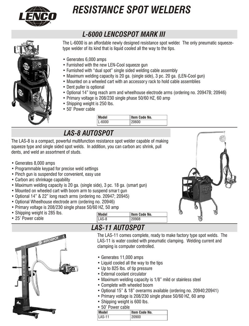
LENCO L-6000 LENCOSPOT MARK III User manual

LENGII
MARK
III
SPOT
WELDER
L-6000
»WARNIN
GS
AND
SAFEGUARDS
FOR
WELDING
AND
CUTTING
OPERATIONS
Important
-
Protect
yourself
and
others
!_
Remember
that
-safety
depends
on
you.
The
operator,
supervisor,
and
‘
helper
must
read
and
understand
all
warning
and
safety
information
provided
in
these
instructions.'Serious
injug
or
death
could
result
if
welding
equipment
is
not
properly
installed,
used
and
maintained.
Training
and
proper
supervision
are
most
important
for
a
safe
work
place.
Installation,
operation,
repair
work,
and
maintenance
must
be
preformed
by
qualified
personnel.
Retain
these
instructions
for
future
use.
A
f
ELECTRICAL
SHOCK
CAN
CAUSE
INJURY
OR
DEATH
V
-;
';
Install
and
maintain
equipment
in
accordance
with
the
National
Electrical
Code
NFPA
70
and
a
local
codes.
Do
not
service
or
repair
equipment
with
power
on.
Do
not
operate
equipment
with
I
;
protective
insulators
or
covers
removed.
Service
or
repair
to
equipment
must
be
done
by
qualified
‘
"
"
e-
‘
and/or
trained
personnel
only.
Maintain
welding
head,
work
clamps,
welding
cable,
and
welding
machines
and
related
equipment
in
good
safe
operating
condition.
Replace
all
worn
or
damaged
insulation.
Occasionally,
check
all
connections
to
determine
if
they
are
mechanically
strong
and
electrically
adequate
for
the
current
required.
Never
immerse
electrodes
in
water
for
cooling.
-
. I
g
V
-
_
References;
See
Safety
.and
Operating
References
A,
E
H,
I.
.
"
“
SMOKE,
FUMES,
AND
GASES
CAN
BE
DANGEROUS
TO
YOUR
HEALTH
.
__
»
Keep
smoke,fumes,
and
gases
from
your
breathing
zone
and
the
general
area.
Smoke,
fumes,
and
I
.
;
gases
from
the
welding
process
are
of
various
types
and
strengths,
depending
on
the
kind
of
metal
1
-
. .
being
welded
on.
To
ensure
your
safety,
do
not
breathe
these
fumes
or
gases.
Ventilation
must
be
adequate
to
remove
smoke,
fumes,
and
gases
during
the
welding
procedure
to
protect
operators
and
others
in
the
_
immediate
area.
Fumes
produced
by
welding
or
cutting,
especially
in
confined
areas,
can
cause
discomfort
and
physical
harm
if
inhaled
over
an
extended
period
of
time.
Always
provide
adequate
ventilation
inthe
welding
and
cutting
area
to
insure
breathing
air
is
safe.
Use
air-supplied.
respirators
if
ventilation
is
not
adequate
to
remove
all
fumes
and
gases.
Never
ventilate
with
oxygen,
because
oxygen
supports
and
vigorously
accelerates
fire.
V
References:
See
Safety
and
Operating
References
A,
B,
C,
H,
&
I.
A
_
.
.
_
HOT
PARTS
_
.
Hot
parts
can
cause
serious
burns.
The
area
at and
near
the
work
being
welded
should
be
handled
figs:
with
proper
gloves.
Proper
clothing
should
be
worn
to
prevent
spatter
from
causing
bums.
Never
pick
up
welded
materral
until
1t
has
been
properly
cooled.,References.
See
Safety
and
Operating
References
A,
B,
H,
&_I.
-
.
cnusnmc
_
,
1
-
I
A
The
electrode
tips
and
arms
can
pinch
hands
or
fingers
when
they
are
between
them
and
the
switch
is
57.
"
-
activated.
Hold
the
head
by
both
handles
when
Positioning
the
head
for
welding.
Disconnect
air
line
"/A
'
from
the
welder
before
repairing
or
adjusting
components
on
the
welding
head.

SPOT
WELDING
SPARKS
CAN
CAUSE
FIRES
AND
EXPLOSIONS
’
,.
.
.
.
Remove
any
and
all
combustible
materials
from
the
work
area.
If
this
is
not
possible,
cover
them
to
7
prevent
the
welding
sparks
from
starting
a
fire.
Causes
of
fire
and
explosion
are
any
combustibles
.1
Ll
1
reached
by
flying
sparks
or
heated
materials.
Do
not
wear
any
gloves
or
clothing
that
has
oil
or
fuel
-type
material
on
it.
Always
have
a
properly
working
OSHA
recognized
Fire
Extinguisher
near
and
be
sure
everyone
has
proper
training
in
its
use.
All
hollow
spaces,
cavities,
and
containers
should
be
vented
prior
to
welding
for
they
may
explode.
Make
sure
proper
steps
have
been
taken
to
ensure
that
venting
procedures
will
not
form
flammable
or
toxic
vapors
from
substances
inside
containers.
y
References:
See
Safety
and
Operating
References
A,
D,
E,
F,
G,
and
H
FALLING
EQUIPMENT
g
.
A
Lift
only
the
unit
or
object
to
be
moved
without
any
running
gear,
assessories,
or
gas
cylinders
that
_
may
be
attached
tohit.
Use
equipment
of
a
proper
size
to
lift
and
move
the
unit.
Falling
equipment
can
cause
personal
injury_
and
equipment
damage.
p
1
References:
See
Safetyand
Operating
References
A,
B,
H,
&
I
’
_
Safety
and
Operating
References
A)
ANSI
Z49.
l,
“Safety
in
Welding
and
Cutting”
B)
ANSI
Z87.l,
“Practice
for
Occupationaland
Educational
Eye
and
Face
Protection”
C)
ANSI
Z88_.2,
“Standard
Practice
for
Respiratory
Protection”
I
. _
'
AN
SI:_
American
National
Standard
Institute,
1430
Broadway,
New
York,
NY
10018
I
D)
ANSI
F4.1,
“Recommended
Safe
Practices
for
Welding
and
Cutting
Containers”
'
AWS:
The
American
Welding
Society,
P.O.
Box
351040,
550
NW
Lejeune
RD.,
Miami,
_FL
33135
E)
NFPA
5_lB,
“Fire
Prevention
in
Cutting
and
Welding
Process”
.
F)
NFPA—70,
“National
Electrical
Code”
NFPA:
National
Fire
Protection
Association,
Batterymarch
Park,
Quincy,
MA
02269
G)
CGA
P-l,
“Precautions
for
Safe
Handling
of
Compressed
Gases
in
Cylinders”
CGA:
Compressed
Gas
Association,
1235
Jefferson
Davis
Hwy.,
Arlington,
VA
222,02
H)
Code
of
Federal
Regulations
(OSHA)
29
CFR
1910
US:
U.S.
Government
Printing
Office,
Washington,
DC
20402
I)
CSA
Standard
W1
17.2,
“Safety
in
Welding,
Cutting,
and
Allied
Processes”
'
CSA:
Canadian
Standards
Association,
"17
8
Rexdale
Blvd.,
Rexdale,
Ontario,
Canada
M9W
1R3
2

_
WARRANTY
’
LIMITED
WARRANTY:
Subject
to
the
terms
and
conditions
hereof,
NLC,
Irrc.,
Jackson,
Missouri
warrants
its
products
to
be
free
from
defects
in
workmanship
and
material
at
the
time
of
delivery
by
NLC,
Inc.
NLC,
Inc.
will
honor
warranty
claims
on
products
as
a
result
of
failure
fiom
a
defect
for
a
time
period
of
one
year
from
the
date
of
sale
to
the
original
user.
Upon
return
of
the
merchandise
at
the
user’s
expense,
NLC,
Inc.
reserves
the
right
to
either
repair
or
replace
as
necessary.
This
is
the
only
warranty
either
expressed
or
implied
covering
our
products.
'
i
,)
~
if
Sm
‘Ii
ii
}\
\
_
c
a
'
/£24../5-._.}
/AV
'0
I\
UNPACKING
AND
ASSEMBLY
‘
,
Examine
the
packaging
material
for
shipping
damage,
which
may
indicate
damage
to
the
product
inside.
If
damage
is
found,
contact
the
shipper
to
resolve
any
issues
resulting
from
shipping.
If
no
damage
is
found,
check
the
power
supply
you
intend
to
use
to
see
if
the
plug
andreceptacle
will
mate
properly.
This
machine
requires
single-phase,
208/230
volts,
60/50Hz,
and
60-amp
service
with
delayed
action
breaker.
Have
power
supply
approved
by
a
licensed
electrician.
Also
uses
compressed
air.
,-_
p
Before
you
hook
the
machine
to
the
power
and
air
supplies
do
the
following.
.
0
Bolt
the
cable
support
bracket
to
the
back
of
the
welder,
and
then
secure
the
L-6000
with
supplied
hardware
on
the
cart
as
shown.
‘
0
Fill
the
cooling
unit
with
special
coolant
supplied
(LAS-415)
and
install
on
the
lower
rails
of
the
cart
with
V
‘
the
inlet
and
outlet
fittings
to
the
front
of
the
L-6000.
(Note:
Save
1
quart
[lliter]
to
prime
the
unitl)
e
I
"
Hookup
the
inlet
and
outlet
water
lines
to
the
cooling
unit.
‘
-
Plug
the
cooling
unit
power
cord
into
the
208/230
volt
outlet
on
the
back
of
the
L-6000.
.
-
Removethe
red
plug
on
the
front
of
the
cooling
unit
and
prime
with
coolant.
_
Align
the
holes
in
the
ends
of
the
LEN-COOL
gtm
cable
assembly
and
A-200-10
single
side
cable
"
assembly,
on
opposite
sides
of
the
secondary
leads
on
thefront
of
the
L-6000._
(The
secondary
lead
is
in
the
center.)
Bolt
them
tightly
together
with
the
flat
sides
making
contact.
Make
sure
to
attach
the
LEN-
COOL
gun
and
the
single
side
cable
assembly
on
opposite
sides
of
the
secondaryleads.
0
Plug
the
control
cord
of
either
assembly
into
the
mating
receptacle
on
the
front
of
the
L‘-6000.
CAUTION:
When
using
the
LEN-COOL
gun
assembly,
take
care
to
ensure
the
electrodes
and
the
other
cable
assembly
are
n_ot'contacting
one
another
or
contacting
any
conductive
material
(use
enclosed
tip
covers).
0
Plug
the
air
fitting
on
the
welding
head
into
the
snap
fitting
on
the
front
of
the
L-6000.
0
I
Hang
the
welding
head
on
the
accessory.rack
and
place
the
cable
assembly
out
of
the
work
area.
3

To
hook
the
machine
to
the
power
and
air
supplies
do
the
following.
‘
0
Attach
the
shop
air
supply
hose
to
the
male
fitting
of
the
air
regulator
on
the
back
of
the
L-6000.
0
Tum
the
air
pressure
on
and
set
the
regulator
to
80
psi.
1
»
~
Turn
off
the
breaker
to
the
shop
power
receptacle,
attach
the
50-foot
power
cord
to
the
shop
electrical
supply,
and
then
turn
the
breaker
back
on.
0
Tum
-on
the
power
switch
on
the
front
of
the
welder
and
inspect
the
entire
system
for
air
and
water
leaks.
(The
cooling
unit
starts
and
stops
with
the
power
switch.)
,
0
Set
the
timer
control
on
the
front
of
the
machine
to,3.
I
'
E
‘
0
Set
switch
for
either
single
side
or
squeeze
type
weld
procedure.
0
Set
switch
for
Automatic
Operation."
.
.
TEST
WELDS
I
j
. _
.
"
Cut
four
to
six
pieces
of
metal
similar
to
that
which
you-plan
to
weId,
and
clean
the
2
outside
areas
to
bare
metal.
Clamp
two
pieces
together
and
support
them
so
the
welding
head
can
clamp
across
them
to
make
a
weld.
Remove
any
combustibles
from
the
area.
Also
protect
any
nearby
items
which
could
be
damaged
by
flying
sparks.
Put
on
your
safety
glasses
and
any
other
required
safety
gear
as
needed.
Make
a
test
weld.
Adjust
timer
control
and
air
pressure
until
desired
Weld
is
achieved.
M
SINGLE
SIDE
WELDINGCABLE/GROUND
CLAMP
p
In
order
to
improve
perfonnance
and
operating
efficiency
of
the
single
side
welding
fLlI1ClIlOI1,
we
have
now
incorporated
a
single
electrode
and
ground
clamp
in
place
of
the
“dual
spot”
system.
Because
of
the
amount
of
power
generated
by
the
L-6000,
this
will
allow
the
user
greater
control,
allowing
for
a
better_weld.
Instructions
for
use
are
as
follows:
.
I
' '
IMPORTANT:
Wear
proper
welding
gloves
as
the
electrode,
ground
clamp,
and
area
being
welded
can
'
become
very
hot.
1.
Unplug
the
switch
cord
on the
front
panel
of
the
machine
and
plug
in
the
switch
cord
for
the
single
side
2.
Set
the
timer
on
2
(you
can
adjust
up
or
down
depending
on
metal
thickness
or
local
line
voltage
-
conditions).
A_
»
.
_
3.
_
Connect
the
ground
clamp
firmly
on the
same
panel
you
are
welding
on.
'
.
V
'
NOTE":
Periodically
check
to
make
sure
the
‘/2”
bolt
that
connects
the
ground
clamp
to
the
cable
lug
.
"remains
TIGHT.
If
allowed
to
work
loose,
a
faulty
comrection
will
occur,
resulting
in
overheating
and
'
arcing.
A
,
4.
Press
the
electrode
fnmly
to
the
panel
with
enough
pressure
to
close
any
gaps.
A
5.
Press
the
switch
on
the
handle
and
hold
it
down
until
the
welding
cycle
stops
automatically.
SINGLESIDE
ELECTRODE
CARE
AND
SERVICE
'
Q
DRESSING
THE
TIP:
The
fastest
way
to
dress
the
tip
is
to
use
the
PTS-100
Tip
Sharpener.
Place
the
tip
sharpener
over
the
electrode
as
you
would
a
pencil
sharpener.
Apply
pressure
and
twist
the
sharpener
several
revolutions
to
the
right.
The
hardened
tool
steel
bit
will
quickly
sharpen
t-he
copper
tip
to
its
original
1/8”
diameter.
Use
a
file
to
dress
the
face
of
the
welding
tip.
KEEP
THE
TIP
DRESED
TO
1/8”
_
DIAMETER
FOR
CONSISTENT
WELDING
RESULTS.
0
REMOVING
THE
TIP:
Tap
the
side
of
the
copper
electrode
gently
several
times
with
a
bumping
hammer
‘
to
loosen
the
taper
fit.
The
tip
is
then
normally
loose
enough
to
remove
by
hand.
UNDER
NO
CIRCUMSTANCES
SHOULD
YOU
ATTEMPT
TO
REMOVE
THE
TIP
BY
TURNNG
IT
IN
THE
ELECTRODE.
The
tip
is
held
in
with
a
No.
1
Morris
Taper
(N
o.
4RW)
and
any
attempt
to
turn
it
will
gall
the
inside
of
the
electrode
which
will
cause
poor
contact
between
the
tip
and
electrode
or
ruin
the
elecrmde
.
A
4

INSERTING
TIP:
Wipe
the
No.
1
Morris
Taper
(No.
4RW)
clean
and
use
the
STSW
Brush
to
clean
the
.
inside
of
the
electrode.
This
will
clean
out
any
metal
filings
and
corrosion
that
may
have
built
up
inside
the
electrode.
Press
the
tip
in
with
HAND
PRESSURE
ONLY.
DO
NOT
HAMMER
THE
TIP
INTO
THE
ELECTRODE.
Never
insert
a
“cold”
tip
into
a
hot
electrode.
You
should
be
able
to
hold
the
copper
electrode
body
with
bare
hands
before
inserting
a
cold
tip.
If
by
accident
you
should
bum
a
hole
in
the
panel,
it
is
likely
that
some
steel
will
be
fused
to
the
copper
tip.
Remove
the
fused
steel
by
nipping
the
tip
ends
with
pliers
or
diagonal
cutters.
Redress
tip
with
LENCO
Tip
Sharpener
PTS-100
before
continuing.
The
tips
will
normally
last
about
l0
months
to
a
year.
Reorder
new
tips
from
your
LENCO
distributor.
CABLE
CONNECTION:
Keep
bolts
tightened
at
the
welder
cable
comrection.
Good
contact
means
good
welds.
BEST
POSITION
OF
ELECTRODES
FOR
WELDING
WITH
THE
SDIGLE
SIDE
ELECTRODE
J
INT
LAP
JOINTS
FLANGE
O
/’
ON
LAP
JOINTS
PLACE
.
I
\
l
ELECTROD$
CLOSE
T0
i
'
ON
FLANGE
JOINTS
PLACE
I.
TOP
EDGE
FOR
A
TIGHT
I.
ELEcTRooEs
on
THE
came
,
_
SEAM
THAT
REDUCE5
.
FLANGES
AND
SPOT
WELD
FINISHING
TIME.
CLOSE
TO
VICE
GRIP
JAWS.
I
\\
HELPFUL
WELDINGHINTS:
Use
vise
grips
on
all
flange
joint
and
drip
rail
applications
to
bring
the
parts
closely
together.
Weld
near
the
vise
grip
jaws
where
the
fit-up
is
tight.
‘
A
few
sheet
metal
screws
can
be
used
on
lap
joints
to
position
the
panel
for
spot
welding.
Make
sure
the
paint
has
been
removed
from
the
joints.
,
"
On
long
splice
jobs,
start
in
the
middle
of
the
panel
and
spot
weld
in
one
direction,
for
example,
'
the
middle
of
the
panel
to
the
doorpost.
“Start
again
in
the
middle
and
complete
the
panel
welds
to
the
5
taillight
area.
This
is
an
additional
aid
in
eliminating
distortion.
l
.
Removal
of
burrs
on the
newly
cut
panel
ensures
getting
good
metal-to-metal
contact
when
body
pressure
A
is
applied
to
the
electrodes.
Burrs
and
dents
cause
an
air
space
between
mating
parts
and
prevent
metal
contact.
-
'
.
e
.
5

(D
.
E
A
-
6
I
eh
/
€"
@
II
<<<<<<<<<<<<<<<<[r
;/
\£(C(
1;,
.1’
Q3?
5"/~
ti)
@@
,
I
.4
e
"
@
\_l
\u‘I@
Tc!
J
\
.
*
CABLE
ASSEMBLY-RIGHT
SIDE
ITEM#
PART#
DESCRIPTION
l.
26125.
Complete
Power
Cable
2.
21122
l0’
x
4’
Cable
W/Lug
and
Electrode
Holder
UJ
21050
Welding
Tip
——
Regular
(pkg.
of
2)
-P-
29449
Molded
Handle
U1
23170
Push
Button
Switch
w/Retaining
Nut
F“
29688
Control
Cord
w/Plug
and
Ties
>1
29685
Plug
Only
CABLE
ASSEMBLY-
GROUND
ITEM#
PART#
DESCRIPTION
-
8.
26126
Complete
Ground
Cable
Assembly
9.
26127
5’,
4/0
Cable
w/Lugs
and
Hardware‘
l0.
I
02077‘
C-Style
Ground
Clamp
w/Bolt

0
PATCH
PANELS:
If
patch
panels
are
cut
from
sheet
metal
to
cover
rust
areas,
make
the
patch
big
enough
to
extend
beyond
the
rust
area
into
good
body
metal.
In
resistance
welding,
the
out-putcables
are
purposely
bound
together
to
deliver
more
power
to
the
weld.
Ifthe
bands
should
become
cut,
tape
the
cables
so
they
are
always
bound
together.
You
will
always
make
good
welds,
panel
after
panel,
if
four
conditions
are
met:
1.
Clean
metal
.
.
2.
Good
fit-up
3.
Proper
time
setting
A
4.
Correct
tip
diameter
0
BURN
THROUGH:
Burn
through
is
caused
by
one
of
the
following:
1.
Paint
was
not
removed
from
the
mating
panels.
2.
There
were
air
gaps
between
the
mating
metal
parts.
.
The
timer
setting
was
too
high
for
the
thickness
of
the
metal
being
welded.
’
The
welding
tips
were
removed
from
the
work,
before
the
welding
cycle
wasicompleted.
.
The
tip
diameters
were
not
equal.
'
U1:>UJ
The
L-6000
must
be
plugged
into
a
208/230
volt,
single
phase,
60/50I—Iz,
fused
for
60
Amps.
"
In
case
the
L-6000
does
not
operate",
check
the
main
fuse
box
of
the
building
wiring
to
see
if
the
main
circuit
fuses
are
not
blown.
‘
WELDING
CYCLE
FOR
THE
LEN-COOL
GUN
-
.
0
‘When
the
switch
on
the
upper
handle
is
pressed,
the
tips
will
compress
the
panels
together.
Ifthe
button
is
.
released
the
tips
will
open.
V
_
0
1.5
seconds
after
the
-tips
are
closed
the
microprocessor
takes
over
and
welds
for
the
time
determined
by
the
timer
setting.
'
P
,
"
'
I
0
Maintain
pressure
on
the
weld
for
one-half
second
after
the
weld
is
complete,
and
then
release
the
switch
to
unclamp
the
panel.
0
_
In
case
the
above
fails
to
produce
a
satisfactory
weld,
check
weld
area
for
contact
between
panels,
adjust
-
timer,
or
air
pressure
and
repeat.
_ _ g
..
7

\_"~"‘*
.\
PARTS
DIAGRAM
AND
ITEM
CODE
NUMBERS
FOR
THE
SQUEEZE
GUN
ASSEMBLY
'
are
(B
,.
>\
g
II
é
._
@
t
.
:
_
:
X
@
1
"
/-J
5
»
~—~.
r"
.1/'
.
‘ET.
./>'~':__;
,
-I
I
'
@'\,-e’
I
J
I
\
e'.\.
Z?
1
._"""\
~\_
.
/,
s__\
.
6
\“\_l
.__._
___.._.._§“_'
3‘?
is
,.
'91
av
A
/'/I
‘
®
L-—-—-—-—-7i
[6
Il(I0fi
@_
$9
®
.
é
;
@
.
Part
#
.
Description
V
Part
#
Description
26144
Welding
tip
w/RW
taper
(pkg
2)
26550
Hardware
kit
(2ea.
1
1/a”bolts,
flat
&
lock
washers)
IQ
26500
Complete
clamp
arm
assembly
26551
Hardware
kit
(2ea.
1”bolts,
flat
&
lock
washers)
_
U-)
26505
Clamp
arm
water
tube
assembly
27447
Push
button
switch
-{>-
26495
Hose-water
w/2-90°
1/16”
fittings
26193
Control
cord
w/plug
-
7’
U1
265-l5
Water
nozzle
w/”O”-ring
(26510)
26490
Casting
hinge
pin
w/retaining
clips
(2)
O\
26520
Water
hose
fitting
w/clamp
26163
Handle
(central)
\l
26530
Insulator
bushings
(2)
26470
Air
cylinder
pin
w/retaining
clips
(upper
&lower)
O0
26440
Cam
adjuster
w/
“O”
ring
26405
Air
hose
W/male
air
fitting
&
female
threads
R0
26540
Casting
hinge
pin
retaining
clips
(2)
26400
Hose
only
—
water
&
air
-
8’
I-—l
O
26460
Air
cylinder-complete
26465
Air
cylinder
cap
3-1
;_i
26485
Casting
w/set
screw-lower
26466
Air
cylinder
cup
ring
)-I
IQ
26560
Roll
pin
(2)
26467
Air
cylinder
piston
I-1
U.)
26570
26468
Air
cylinder
spring
>—l
-5
26480
Cap
screws
(upper/lower
castings
[2])
Casting
(handle
side)
w/cap
screw
-
upper
26469
Air
cylinder
housing
I—l
U1
26181
Cable
w/cover,
lugs,
&
hardware
26420
Water
coupler
set
(male
&
female)
w/clamps
we
O\
26162.
Handle
w/
grip
(rear)
29685
Male
plug
—
control
cord
8

%
§j§
We
;i;_f
‘
\I:§I(:§'
.\
\
.
\\
\\
i..‘.h
.
\\
‘I
in
/
\.
/
/
,,.,/'/
0
I
A
’_/
1
,\I—)/A
»
4
\
PARTS
DIAGRAM
AND
ITEM
CODE
NUMBERS
FOR
THE
L-6000
MARK
HI
@
3
f
Q
“L”
0
..
$\\
‘
Q
.
I
.
>
$
$\
'
/
Q
Q
-
Q
Y
@__~/
/R1’/4
’,
\
Q‘
/
/
.f-uijw
7,
,/E%/
-
\
.
..
/*1
Q‘
Part
#
Description
e
Q
0
5
32:
Part
#
A
-
.
Description
26100
Welding
Transformer
(208/230V)
>-a
U1
26110
Caster
w/Brake
(4”)
26304
Contactor
-
'
v-A
O\
26430
Coolant
Circulator
.
U)
29150
Control
Transformer
-
230V
i—
\I
263
80
Timer
Control
Assembly
-#-
23340
Air
Regulator.
)—l
O9
23315
Air
Valve
.
U1
23350
Receptacle
(Circulator)
0-
\O
29340
Power
‘Cable-50’,l0/3
wire
ON
29745
Switch
“On-Off’
26410
Panel
Air
Coupling
(female)
\l
23330
Switch-Auto/Close
29680
Receptacle
_—
accepts
2
prong
p
ug
O0
23330
Switch-Len-Cool/Single
Side
26425
l
Water
Coupler
Set
(90°
male
&
female)
\O
29690
Timer
Indicator
Knob
23415
Coolant
—_
one
gallon
I-
O
29230
Strain
Relief
26260
Complete
Squeeze
Type
Welding
Head
&
Cable
Assembly
(Len-Cool
Gun)
26349
Cabinet
1
26450
Cable
Support
Bracket
w/Handles
26200
26109
L-6000
Cart-Complete
Caster
w/o
Brake
(4”)
\-
9.

NOTES
/
1'0

NOTES
ll

L
E
V
L-5000
WIRING
DIAGRAM
L
E0
‘VI
®
cnouunr
‘vi
®
Q-yi
GREEN
“Pl
230V
RECEPTACLE
TO
PUMP
LAS—35O
dwv
09
asvner
EITDN
s
ov
anon
022
.Ll'1dNI
(INITOHEJ
IQ
on/orr
I
swrrcn
LIGHT
-
5
.
..'
"'
BLACK
5
#1-P
74
E11
'
I
CONTROL
|
CONTACTOR
l
TRANSFORMER
B—304
A_101
-
I
I
|
V-Ia
VIE
'.'
HO
>10
)I3V'IH
YELLOW
-
!\
Cal
PRIMARY
WELD
YELLOW
z#
cIV-L
A908
TRANSFORMER
B—
1
00
SEC
ONDARY
I
I
OUTPUT
--
T0
GUNS
BLACK
TRIGGER
RECEPTACLE
A—
3
1
6
c
RED
AIR
‘VALVE
_
»
_
LAS—315
swrrcn
SW"
e
PINCH
can
AUTO/CLOSE
.
DUAL
LEAD
‘
‘
ms-sac
I-As'3,3°
.1
RED
\
PC
BOARD
B-380
. .
TIMER
_
.
'
IELLXI-III
0
.
I
BU
annexe
Q
norrsx
D
MS
v
MS
o
/wz
~
/wz
o
/wz
/wz
‘I
oo
MS
,
.
MS
1
oo
>INV1EI
o
DANGER:
DO
NOT
CONNECT
#2
and’
#3
transformer
leads
to
contactor
at
same
time.
For.
208V
service
—
disconnect
wire
#3
from
contactor
and
replace
with
wire
#2,
insulate
wire
#3.
’
For
230V
service
—
disconnect
wire
#2
from
contactor
and
replace
with
wire
#3,
insulate
wire
#2.
e
Lenco
Automotive
Equipment
--
For
Technical
Assistance
Call;
(800)
747-4743
'
NLC,
INC.,
319
W.
Main
Street,
Jackson,
MO
63755
Phone
(573)
243-3141,
Fax
(573)
243-7122
I
-.
Form
No.
L6-0604
Other manuals for L-6000 LENCOSPOT MARK III
2
Table of contents
Other LENCO Welding System manuals