Redarc SBI12-BLD Manual

BMS Load
Disconnect Isolator
SBI12-BLD
INSTALL MANUAL

2 | EN English
EN ENGLISH
PRODUCT FUNCTION
The SBI12-BLD is used in conjunction with a REDARC Maanger30 Battery
Management System in a 12V negative ground automotive system to protect
the auxiliary battery from excessive discharge. Specically designed for use
as the load disconnect solenoid controlled by the BMS, the black (earth
wire) should be connected to the load pin of t he BMS. The BMS sets the
turn on and off points through its settings and switches this black wire (earth
when loads should be on, no earth when loads should be off), and there is
additional voltage thresholds monitored by the SBI12-BLD to ensure reliable
solenoid engagement. The Isolator monitors the auxiliary battery and when
this drops below the Turn OFF voltage, the solenoid will open, disconnecting
the load. The solenoid will close again when the auxiliary battery voltage
reaches the Turn ON Voltage. A delay Time is built into the Unit for each
transition to reduce the chance of chattering.
The voltage must remain at or above the Turn ON Voltage for a Delay Time
ON period before the solenoid closes. Similarly the voltage must remain at or
below the Turn OFF Voltage for a Delay Time OFF period before the solenoid
opens.
WARNING & SAFETY INSTRUCTIONS
Save these instructions — This manual contains important safety
instructions. Do not operate the system unless you have read and understood
this manual. REDARC recommends that the SBI12-BLD referenced in this
manual be installed by a suitably qualied person.
Disclaimer: REDARC accepts no liability for any injury, loss or property
damage which may occur from the improper or unsafe installation or use of
its products.
WARNING: Risk of explosive gases: Working in vicinity of a lead-acid
battery is dangerous. Batteries generate explosive gases during normal
operation. For this reason, it is of utmost importance that you follow the
instructions each time you use the charger.
CAUTION
NEVER smoke or allow a spark or ame in vicinity of battery or engine. This
may cause the battery to explode.
Be extra cautious so as to reduce the risk of dropping a metal tool onto a
vehicle battery. Doing so might cause the battery to spark or might short-
circuit the battery or other electrical parts that may cause an explosion.
Remove personal metal items such as rings, bracelets, necklaces, and
watches when working with a lead-acid battery. A lead-acid battery can
produce a short-circuit current high enough to weld a ring or the like to
metal, causing a severe burn.
A SPARK NEAR A BATTERY MAY CAUSE THE BATTERY TO EXPLODE.
TO REDUCE THE RISK OF A SPARK NEAR A BATTERY WHEN
CONNECTING THE BATTERY INSTALLED IN A VEHICLE TO THE
ISOLATOR, ALWAYS DO THE FOLLOWING:
Position DC cords to reduce the risk of damage by the vehicle hood, door,
or moving engine part.
Stay clear of fan blades, belts, pulleys and other parts that can cause injury
to persons.
Check polarity of battery posts. The POSITIVE (POS / P / +) battery post
usually has a larger diameter than the NEGATIVE (NEG / N / –) battery post
however you should always check the label on the battery.
Determine which post of the battery is grounded (connected) to the
chassis. If the negative post is grounded to the chassis (as in most
vehicles), see (1). If the positive the post is grounded to the chassis see (2).
(1) For a negative-grounded vehicle, connect the POSITIVE (Red) terminals
from the Battery Isolator to the POSITIVE (POS, P, +) ungrounded post of
each battery. Connect the NEGATIVE (Black) lead to a metal part of the
frame or the vehicle chassis, away from the battery. Do not connect the
connect to the carburettor or fuel lines.
(2) For positive-grounded vehicles, connect the NEGATIVE (Black) lead
from the Battery Isolator to the NEGATIVE (NEG / N / –) ungrounded post of
the battery. Connect the POSITIVE (RED) terminals to the POSITIVE (POS /
P / +) post of each battery. Do not connect the connect to the carburettor,
fuel lines, or sheetmetal body parts. Only the start battery should be
connected to the chassis.
PERSONAL SAFETY PRECAUTIONS:
To assist with the safe working with batteries:
Consider having someone close by to come to your aid when you are
working with the Battery.
Have plenty of fresh water and soap nearby in case battery acid contacts
skin, clothing, or eyes.
Wear complete eye protection and clothing protection. Avoid touching eyes
while working near a battery.
If battery acid contacts your skin or clothing, remove the affected clothing
and wash the affected area of your skin immediately with soap and water.
If battery acid enters your eye, immediately ood the eye with running cold
water for at least 10 minutes and seek medical assistance immediately.
NOTICE
Over discharge risk. Ensure that the Turn OFF voltage is suitable for the
specications provided by the battery manufacturer.
It is recommended that Start and Auxiliary Batteries be of similar chemical
characteristics when charging via the Smart Start®SBI.
The SBI12-BLD will achieve best results when proper battery maintenance
is regularly performed. This includes but is not limited to checking water
and specic gravity levels of the battery. Refer to the battery manufacturers
manual for more details.
Fuses or Circuit breakers of appropriate rating must be installed to protect
the vehicle system.
Fuses must be installed as close as possible to the battery.
IMPORTANT! Do NOT make any connections to the control terminals found
on the front of the unit. Connecting to the control terminals on the front of
the SBI may cause damage to the unit and/or equipment connected to it.
Connecting to the control terminals will void the warranty of the unit.
Do NOT connect to the
control terminals.
EN
FR
English 2–4
francais 11–13
DE
IT
ES
PL
AR
Deutsch 5–7
Italiano 14–16
Español 8–10
polski 17–19
Arabic 20–22

EN English | 3
SPECIFICATIONS
System Voltage 12V Nominal
Turn ON Voltage 10.2V
Turn OFF Voltage 10.0V
Turn ON Delay 5 seconds
Turn OFF Delay 10 seconds
Instant OFF Voltage 9.0V
Max. Continuous Current 100Amps
Max. Inrush Current 400Amps
Standby Current <5mA
Operating Current <0.1A
Dimensions 75×70×80mm (2.95"×2.75"×3.15")
Weight 200g (0.4 lbs)
Warranty 2 years
Standards CE, C-Tick, AS/NZS CISPR11:2004
Main Stud Torque 5– 6.2 Nm
Voltages Specied are ±100 mV
RECOMMENDED FUSES AND CABLING
Suitably sized wire and fuses for the connected loads should be used.
REDARC recommend using MIDI fuses along with a quality fuse holder to
match (cables not included).
Part Numbers
FK40 40 A Fuse Kit
FK60 60 A Fuse Kit
MIDI Fuse with Holder Fuse Assembly
INSTALLATION INSTRUCTIONS
1. Mount the SBI12-BLD securely in a convenient location near the auxiliary
battery bank. Do not mount in direct engine heat.
2. Install in the order described below:
Ground connection. Connect the SBI12-BLD ground terminal to the BMS
Load Disconnect terminal. NOTE: A good connection will ensure correct
switching voltage.
Select correct circuit Breaker/Fuse sizes and install at battery end of the
positive cable.
LED Connections (optional). Connect a wire from the Blue wire of the
SBI12-BLD to the positive end of an indicator LED (15mA limited current
draw) or LED/resistor combination.
Install and operate in conjunction with the BMS user manual.
CAUTION: Over discharge risk. Ensure that the Turn OFF Level set
on the BMS are suitable for the specications provided by the battery
manufacturer.
NOTICE: It is normal for the LED to stay ON whenever the auxiliary
battery is in a condition suitable for running loads.
FAULT INDICATION
NOTE: The LED will be on when the SBI12-BLD is active (on).
Should a fault occur, the SBI12-BLD is set to notify the operator of the fault.
The LED will ash repeatedly with the following sequences:
CODE 1 2 Flashes Over-Voltage
CODE 2 3 Flashes Voltage Drop or Excessive Current Draw Fault
Fault Code 1:
If the battery connected to the SBI12-BLD should rise above 16.5V, the
SmartStart®will:
Disconnect, to prevent the source of over-voltage reaching the load.
Flash the LED 2 times for 20 seconds, then reassess the fault condition,
continuing until the fault is cleared.
Fault Code 2:
If the SBI12-BLD detects a voltage drop across its contacts of greater than
1V for more than 30 seconds then the unit will:
Immediately protect itself and the load by disconnecting the load and;
Flash the LED 3 times for 20 seconds, then reassess the presence of a
fault, continuing until the fault is cleared.

4 | EN English
STANDARD WIRING DIAGRAMS
Ensure adequately sized cable is used.
Ensure the auxiliary battery is properly grounded to a common chassis
earth point.
Ensure the SBI12-BLD ground wire is wired to the load Disconnect terminal
of the BMS.
When using fuses make sure that the fuse makes a good low resistance
connection.
Fuse/Circuit Breaker ratings are dependent on the type of installation and
the size of the loads.
NOTICE: For correct operation via the vehicle input, the BMS1230S3R
must be connected to a battery and not directly to either an alternator or
generator output.
Override
Wire
(BLUE)
Ground
Wire
(BLACK)
Mounting
Point
Auxiliary
Terminal
Start
Terminal
Solar
Panel
50A
Fuse Start
Battery
Essential Loads**
Display
BMS1230S3R
+
+
Mains AC from
mains power
(rear side) AC
MAINS
-
+
Non-essential
Loads**
Auxiliary
Battery
1 2 3456
2
Battery
Sensor
40A
Fuse
Load
Fuses*
Ignition
Trigger
SBI12-BLD
+
*Fuses are not supplied. The size of this fuse relates to the total current draw of all the loads connected to the auxiliary battery, and should be rated slightly
higher than this.
**Essential loads are loads which must be left on at all times, until the battery is at. Non-essential loads are those switched off when the battery reaches a
particular low-charge level, which can be set in the 'Advanced Settings' menu on the RedVision®Display.
FREQUENTLY ASKED QUESTIONS
Is the unit protected against voltage spikes?
Yes, the SBI12-BLD incorporates a number of spike protection components specically designed to reduce the risk of damaging the unit. The SBI12-BLD is also
designed to prevent any spikes generated by the solenoid coil from affecting any vehicle equipment.
What does the red LED indicate?
The red LED indicates the solenoid is activated and therefore the battery is supplying power to the load. A ashing red LED during operation indicates a fault.
Can the voltage limits and time delay settings be changed?
Yes. Both upper and lower voltage limits & on and off times can be changed. However, this needs to be done at the time of manufacture and will incur a cost.
We are experiencing repetitive switching for our SBI12-BLD. What could be causing this?
This can occur for one of two reasons. Firstly, switching an excessively large load which would drop the battery to below its lower voltage limit and causing
the SBI12-BLD to turn off. After turning off the load, the battery would recover in voltage; If the battery voltage climbs higher than the turn on threshold, the
SBI12-BLD would turn the loads back on.
Secondly, voltage drop due to cable length (ie. the SBI12-BLD being mounted too far from the auxiliary battery) can cause the voltage at the battery terminal on
the SBI12-BLD to be lower than at the auxiliary battery, which can also cause the unit to switch off. Voltage seen by the SBI12-BLD will now rise again until the
SBI12-BLD switches back on. This switching will continue until the cause of voltage drop is removed. On and Off time delays are built into the product to avoid the
solenoid contacts chattering in this scenario.
Can I use the SBI12-BLD on a positive chassis vehicle?
Yes. Please contact REDARC for further information.

DE Deutsch | 5
DE DEUTSCH
PRODUKTFUNKTION
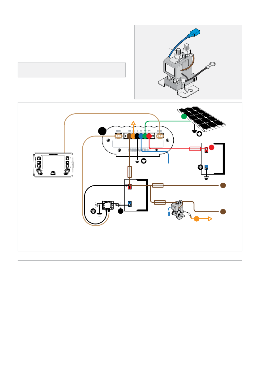
Der SBI12-BLD wird in Verbindung mit einem REDARC Maanger30-
Batteriemanagementsystem in einem 12-V-Kfz-System mit negativer
Masse verwendet, um die Zusatzbatterie vor übermäßiger Entladung zu
schützen. Der schwarze Erdungsdraht wurde speziell für die Verwendung
als Lasttrennmagnet, der vom BMS gesteuert wird, entwickelt, und sollte
an den Lastpin des BMS angeschlossen werden. Das BMS legt die Ein-
und Ausschaltpunkte durch seine Einstellungen fest und schaltet diesen
schwarzen Draht um (Masse, wenn die Lasten eingeschaltet sein sollen, keine
Masse, wenn die Lasten ausgeschaltet sein sollen), und es gibt zusätzliche
Spannungsschwellen, die vom SBI12-BLD überwacht werden, um ein
zuverlässiges Einschalten des Magnetventils zu gewährleisten. Der Isolator
überwacht die Zusatzbatterie, und wenn diese unter die Ausschaltspannung
fällt, öffnet sich das Magnetventil und schaltet die Last ab. Das Magnetventil
schließt wieder, wenn die Spannung der Zusatzbatterie die Einschaltspannung
erreicht. Für jeden Übergang ist eine Verzögerungszeit in das Gerät eingebaut,
um die Gefahr des Flatterns zu verringern.
Die Spannung muss für die Dauer der Einschaltverzögerung auf oder über
der Einschaltspannung bleiben, bevor das Magnetventil schließt. Ebenso
muss die Spannung für eine AUS-Verzögerungszeit auf oder unter der
Ausschaltspannung bleiben, bevor der Magnet öffnet.
WARN- UND SICHERHEITSHINWEISE
Bewahren Sie diese Anleitung auf. Sie enthält wichtige Sicherheitshinweise.
Nehmen Sie das System nur in Betrieb, wenn Sie diese Anleitung gelesen
und verstanden haben. REDARC empehlt, dass der SBI12-BLD, auf den
in diesem Handbuch verwiesen wird, von einer entsprechend qualizierten
Person installiert wird.
Haftungsausschluss: REDARC übernimmt keine Haftung für Verletzungen,
Verluste oder Sachschäden, die durch die unsachgemäße oder unsichere
Installation oder Verwendung seiner Produkte entstehen können.
WARNUNG: Gefahr durch explosive Gase: Das Arbeiten in der Nähe
einer Bleisäurebatterie ist gefährlich. Batterien erzeugen bei normalem
Betrieb explosive Gase. Aus diesem Grund ist es äußerst wichtig, bei jeder
Verwendung des Ladegeräts die Anweisungen zu befolgen.
ACHTUNG
NIEMALS rauchen oder Funken oder Flammen in der Nähe der Batterie
oder des Motors gelangen lassen. Dies kann zu einer Explosion der
Batterie führen.
Vermeiden Sie unbedingt, dass Metallwerkzeuge auf eine Fahrzeugbatterie
fallen. Andernfalls besteht die Gefahr, dass die Batterie Funken schlägt
oder die Batterie oder andere elektrische Teile kurzgeschlossen werden,
was zu einer Explosion führen kann.
Legen Sie persönliche Metallgegenstände wie Ringe, Armbänder,
Halsketten und Uhren ab, wenn Sie mit einer Bleisäurebatterie arbeiten.
Eine Bleisäurebatterie kann einen Kurzschlussstrom erzeugen, der hoch
genug ist, um einen Ring oder ähnliches an Metall zu schweißen und
schwere Verbrennungen zu verursachen.
FUNKEN IN DER NÄHE EINER BATTERIE KÖNNEN DIE BATTERIE ZUR
EXPLOSION BRINGEN. UM DAS RISIKO VON FUNKENBILDUNG ZU
VERRINGERN, WENN DIE IN EIN FAHRZEUG EINGEBAUTE BATTERIE
AN DEN ISOLATOR ANGESCHLOSSEN WIRD, GEHEN SIE IMMER WIE
FOLGT VOR:
Platzieren Sie die Gleichstromkabel so, dass die Motorhaube, die Türen
und die beweglichen Motorteile nicht beschädigt werden.
Halten Sie sich von Lüfterügeln, Riemen, Riemenscheiben und anderen
Teilen fern, an denen sich Personen verletzen können.
Prüfen Sie die Polarität der Batteriepole. Der POSITIVE (POS / P / +)
Batteriepol hat normalerweise einen größeren Durchmesser als der
NEGATIVE (NEG / N / -) Batteriepol, aber Sie sollten stets das Etikett auf
der Batterie überprüfen.
Prüfen Sie, welcher Pol der Batterie mit dem Gehäuse geerdet (verbunden)
ist. Wenn der Minuspol am Gehäuse geerdet ist (wie bei den meisten
Fahrzeugen), siehe (1). Wenn der Pluspol mit dem Gehäuse geerdet ist,
siehe (2).
(1) Bei einem Fahrzeug mit negativer Erdung schließen Sie die POSITIVEN
(roten) Klemmen des Batterietrennrelais an den nicht geerdeten
POSITIVEN (POS, P, +) Pol der jeweiligen Batterie an. Schließen Sie das
NEGATIVE (schwarze) Kabel an ein Metallteil des Rahmens oder des
Fahrzeuggehäuses fernab der Batterie an. Schließen Sie den Stecker nicht
an den Vergaser oder die Kraftstofeitungen an.
(2) Bei einem Fahrzeug mit positiver Erdung schließen Sie die NEGATIVEN
(schwarzen) Klemmen des Batterietrennrelais an den nicht geerdeten
NEGATIVEN (NEG / N / –) Pol der jeweiligen Batterie an. Verbinden Sie
die POSITIVEN (ROTEN) Klemmen mit den POSITIVEN (POS / P / +)
Polen der einzelnen Batterien. Schließen Sie den Stecker nicht an den
Vergaser, die Kraftstofeitungen oder Karosserieteile aus Metall an. Nur die
Starterbatterie sollte an das Gehäuse angeschlossen werden.
SICHERHEITSMASSNAHMEN:
Für einen sicheren Umgang mit Batterien:
Holen Sie sich stets Unterstützung durch eine andere Person, die Ihnen bei
der Arbeit mit der Batterie zur Seite steht.
Halten Sie reichlich frisches Wasser und Seife bereit, für den Fall, dass
Batteriesäure mit Haut, Kleidung oder Augen in Berührung kommt.
Tragen Sie einen vollständigen Augenschutz und Schutzkleidung.
Vermeiden Sie es, die Augen zu berühren, wenn Sie in der Nähe einer
Batterie arbeiten.
Wenn Batteriesäure mit Ihrer Haut oder Kleidung in Berührung kommt,
ziehen Sie die betroffene Kleidung aus und waschen Sie die betroffene
Hautstelle sofort mit Wasser und Seife. Wenn Batteriesäure in Ihre Augen
gelangt, spülen Sie das betroffene Auge sofort mindestens 10Minuten lang
mit ießendem kaltem Wasser aus und suchen Sie sofort einen Arzt auf.
HINWEIS
Risiko der Überladung. Stellen Sie sicher, dass die Abschaltspannung den
Angaben des Batterieherstellers entspricht.
Starter- und Zusatzbatterie sollten ähnliche chemische Eigenschaften
aufweisen, wenn sie über den Smart Start®SBI geladen werden.
Der SBI12-BLD erzielt die besten Ergebnisse, wenn die Batterie
regelmäßig gewartet wird. Dazu gehört unter anderem die Überprüfung
des Wasserstands und des spezischen Gewichts der Batterie. Weitere
Einzelheiten nden Sie im Handbuch des Batterieherstellers.
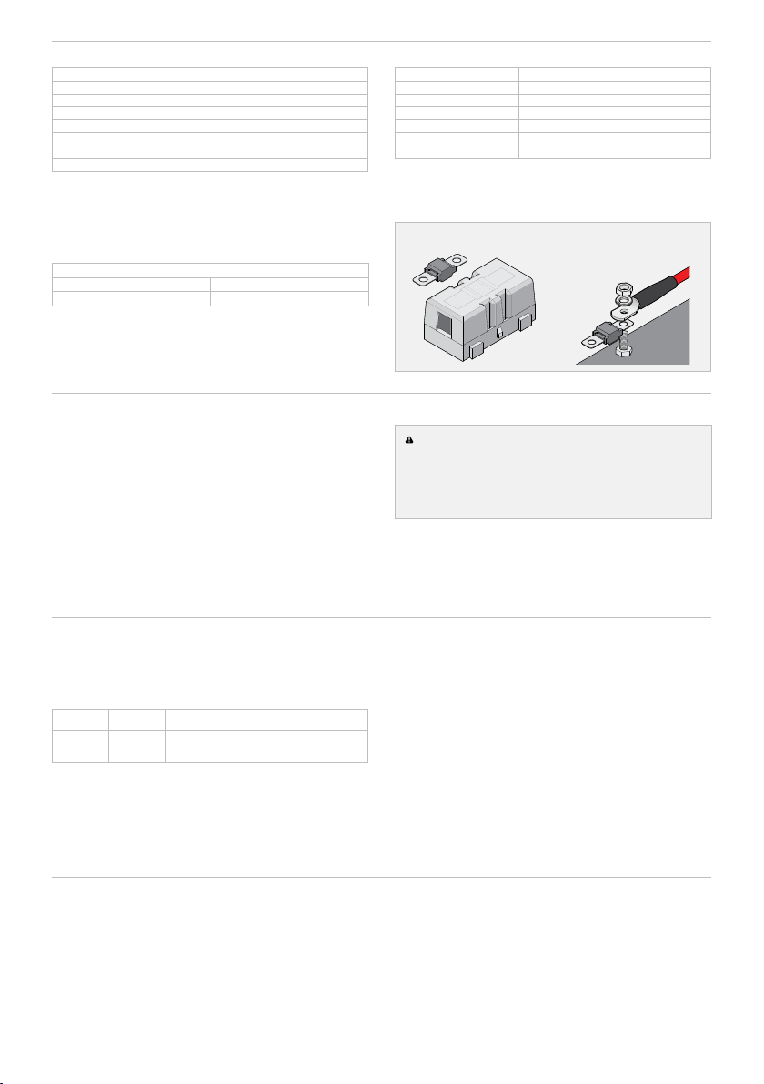
Zum Schutz des Fahrzeugsystems müssen Sicherungen oder
Schutzschalter mit einer geeigneten Leistung eingebaut werden.
Die Sicherungen müssen so nah wie möglich an der Batterie installiert
werden.
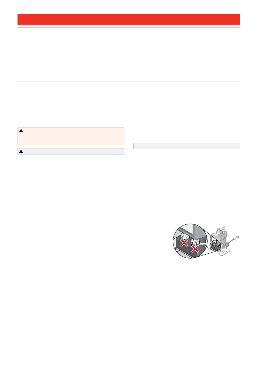
WICHTIG! Nehmen Sie KEINE Anschlüsse an den Steuerklemmen auf
der Vorderseite des Geräts vor. Das Anschließen an die Steuerklemmen
auf der Vorderseite der SBI kann zu Schäden am Gerät und/oder an den
angeschlossenen Geräten führen. Das Anschließen an die Steuerklemmen
führt zum Erlöschen der Garantie für das Gerät.
NICHT an die
Steuerklemmen
anschließen.

6 | DE Deutsch
SPEZIFIKATIONEN
Systemspannung 12V Nominal
Volteinschaltung 10,2V
Voltausschaltung 10,0V
Einschaltverzögerung 5 Sekunden
Ausschaltverzögerung 10 Sekunden
Spannung bei sofortiger
Abschaltung 9,0V
Max. kontinuierlicher Strom 100Ampere
Max. Einschaltstrom 400Ampere
Ruhestrom <5mA
Betriebsstrom <0,1A
Abmessungen 75×70×80mm
Gewicht 200g
Garantie 2 Jahre
Normen CE, C-Tick, AS/NZS CISPR11:2004
Hauptbolzen-Drehmoment 5– 6,2Nm
Angegebene Spannungen sind ±100mV
EMPFOHLENE SICHERUNGEN UND
VERKABELUNG
Es sollten ausreichend dimensionierte Kabel und Sicherungen für die
angeschlossenen Verbraucher verwendet werden. REDARC empehlt
die Verwendung von MIDI-Sicherungen zusammen mit einem passenden
hochwertigen Sicherungshalter (Kabel nicht im Lieferumfang enthalten).
Teilenummern
FK40 40A-Sicherungssatz
FK60 60A-Sicherungssatz
MIDI-Sicherung mit Halter Sicherung– Bausatz
INSTALLATIONSANWEISUNGEN
1. Montieren Sie den SBI12-BLD sicher an einem geeigneten Ort in der
Nähe der Zusatzbatteriebank. Nicht in der Nähe direkter Motorwärme
montieren.
2. In der unten beschriebenen Reihenfolge installieren:
Erdungsanschluss. Verbinden Sie die Erdungsklemme des SBI12-BLD mit
der Lasttrennklemme des BMS. HINWEIS: Eine gute Erdung sorgt für eine
korrekte Schaltspannung.
Wählen Sie die richtige Größe des Schutzschalters/der Sicherung und
installieren Sie ihn/sie am Batterieende des Pluskabels.
LED-Anschlüsse (optional). Verbinden Sie einen Draht vom blauen
Draht des SBI12-BLD mit dem positiven Ende einer Anzeige-LED (15mA
begrenzte Stromaufnahme) oder einer LED/Widerstandskombination.
Installieren und betreiben Sie das Gerät in Übereinstimmung mit dem
BMS-Benutzerhandbuch.
VORSICHT: Gefahr der Überladung. Stellen Sie sicher, dass die
Abschaltspannung des BMS den Angaben des Batterieherstellers
entspricht.
HINWEIS: Es ist normal, dass die LED leuchtet, wenn die Zusatzbatterie
in einem für den Betrieb von Verbrauchern geeigneten Zustand ist.
ANZEIGE VON FEHLERN
HINWEIS: Die LED leuchtet, wenn der SBI12-BLD aktiv (eingeschaltet) ist.
Sollte eine Störung auftreten, wird der SBI12-BLD so eingestellt, dass er
den Betreiber über die Störung informiert. Die LED blinkt wiederholt in den
folgenden Sequenzen:
CODE 1 2 Mal Blinken Überspannung
CODE 2 3 Mal Blinken Spannungsabfall oder übermäßiger Stromverbrauch
Fehlercode 1:
Sollte die an den SBI12-BLD angeschlossene Batterie über 16,5V ansteigen,
wird der Smart Start®:
die Verbindung trennen, um zu verhindern, dass die Quelle der
Überspannung den Verbraucher erreicht.
Die LED blinkt 2 Mal für 20 Sekunden, anschließend erneute Bewertung
des Fehlerstatus und fortfahren, bis der Fehler behoben ist.
Fehlercode 2:
Wenn der SBI12-BLD länger als 30 Sekunden einen Spannungsabfall über
seine Kontakte von mehr als 1V feststellt, verhält sich das Gerät wie folgt:
Sofortiger Selbstschutz und Schutz des Verbrauchers, indem der
Verbraucher abgeklemmt wird, und;
die LED blinkt 3 Mal für 20 Sekunden, anschließend erneute Bewertung des
Fehlerstatus und fortfahren, bis der Fehler behoben ist.

DE Deutsch | 7
STANDARD-VERKABELUNGSDIAGRAMME
Stellen Sie sicher, dass ein ausreichend dimensioniertes Kabel verwendet
wird.
Stellen Sie sicher, dass die Zusatzbatterie ordnungsgemäß an einem
Erdungspunkt des Gehäuses geerdet ist.
Stellen Sie sicher, dass das Erdungskabel des SBI12-BLD mit der
Lasttrennklemme des BMS verbunden ist.
Achten Sie bei der Verwendung von Sicherungen darauf, dass die
Sicherung einen guten, niederohmigen Anschluss hat.
Die Nennwerte von Sicherungen/Leistungsschaltern hängen von der Art der
Installation und der Größe der Verbraucher ab.
HINWEIS: Für den korrekten Betrieb über den Fahrzeugeingang muss das
BMS1230S3R an eine Batterie und nicht direkt an einen Generator oder
einen Lichtmaschinenausgang angeschlossen werden.
Überbrü-
ckungskabel
(BLAU)
Massekabel
(SCHWARZ)
Montage-
punkt
Hilfster-
minal
Start-
Terminal
Solar-
panel
50A-
Sicherung Starter-
batterie
Wichtige
Verbraucher**
Anzeige
BMS1230S3R
+
+
Netz-AC von
Netzstrom
(Rückseite) AC-
NETZ
-
+
Unwichtige
Verbraucher**
Zusatz-
batterie
1 2 3456
2
Batterie-
Sensor
40A-
Sicherung
Belastungs-
sicherungen*
Zündungs-
auslöser
SBI12-BLD
+
*Sicherungen sind nicht im Lieferumfang enthalten. Die Größe dieser Sicherung bezieht sich auf die Gesamtstromaufnahme aller an die Hilfsbatterie
angeschlossenen Verbraucher und sollte etwas höher bemessen sein als diese.
**Wichtige Verbraucher sind Verbraucher, die immer eingeschaltet bleiben müssen, bis die Batterie leer ist. Unwichtige Verbraucher werden abgeschaltet,
wenn die Batterie einen bestimmten niedrigen Ladezustand erreicht, der im Menü „Advanced Settings” (Erweiterte Einstellungen) auf dem RedVision®Display
eingestellt werden kann.
HÄUFIG GESTELLTE FRAGEN
Ist das Gerät gegen Spannungsspitzen geschützt?
Ja, der SBI12-BLD enthält eine Reihe von Überspannungsschutzkomponenten, die speziell entwickelt wurden, um das Risiko einer Beschädigung des Geräts
zu verringern. Der SBI12-BLD wurde auch entwickelt, um zu verhindern, dass die von der Magnetspule erzeugten Spannungsspitzen die Fahrzeugausrüstung
beeinträchtigen.
Was zeigt die rote LED an?
Die rote LED zeigt an, dass das Magnetventil aktiviert ist und somit die Batterie den Verbraucher mit Strom versorgt. Eine blinkende rote LED während des
Betriebs zeigt eine Störung an.
Können die Einstellungen für die Spannungsgrenzen und die Zeitverzögerung geändert werden?
Ja. Sowohl die oberen und unteren Spannungsgrenzen als auch die Ein- und Ausschaltzeiten können geändert werden. Dies muss jedoch zum Zeitpunkt der
Herstellung geschehen und ist mit geringen Kosten verbunden.
Bei unserem SBI12-BLD kommt es immer wieder zu unerwünschten Schaltvorgängen. Was könnte die Ursache dafür sein?
Dafür kann es zwei Gründe geben. Erstens, das Schalten eines zu großen Verbrauchers, der die Batterie unter ihre untere Spannungsgrenze sinken lässt
und den SBI12-BLD zum Abschalten bringt. Nach dem Abschalten des Verbrauchers erholt sich die Batteriespannung; steigt die Batteriespannung über den
Einschaltschwellenwert, schaltet der SBI12-BLD die Verbraucher wieder ein.
Zweitens kann ein Spannungsabfall aufgrund der Kabellänge (z. B. wenn der SBI12-BLD zu weit von der Hilfsbatterie entfernt montiert ist) dazu führen, dass die
Spannung am Batteriepol des SBI12-BLD niedriger ist als an der Hilfsbatterie, was ebenfalls zum Abschalten des Geräts führen kann. Die vom SBI12-BLD erfasste
Spannung steigt nun wieder an, bis sich der SBI12-BLD wieder einschaltet. Dieser Schaltvorgang wird so lange fortgesetzt, bis die Ursache des Spannungsabfalls
beseitigt ist. Es sind Ein- und Ausschaltverzögerungen in das Produkt eingebaut, um ein Klappern der Magnetkontakte in diesem Szenario zu vermeiden.
Kann ich den SBI12-BLD bei einem Fahrzeug mit positiv geerdetem Gehäuse verwenden?
Ja. Für weitere Informationen wenden Sie sich bitte an REDARC.

8 | ES español
ES ESPAÑOL
FUNCIÓN DEL PRODUCTO
El SBI12-BLD se utiliza junto con un sistema de gestión de baterías (BMS,
Battery Management System) REDARC Maanger30 en un sistema automotriz
de 12V con conexión a tierra negativa para proteger la batería auxiliar de una
descarga excesiva. Especícamente diseñado para usarse como solenoide
de desconexión de carga controlado por el BMS, el cable negro (tierra) debe
conectarse al pasador de carga del BMS. El BMS establece los puntos de
encendido y apagado a través de sus ajustes y conmuta este cable negro
(a tierra cuando las cargas deben estar en encendido, sin tierra cuando las
cargas deben estar en apagado), y hay umbrales de tensión adicionales
supervisados por el SBI12-BLD para garantizar una conexión conable del
solenoide. El separador monitorea la batería auxiliar y, cuando esta cae por
debajo de la tensión de apagado, el solenoide se abre y desconecta la carga.
El solenoide se cerrará de nuevo cuando la tensión de la batería auxiliar
alcance la tensión de encendido. La unidad incorpora un tiempo de retardo
en cada transición para reducir la posibilidad de vibraciones.
La tensión debe permanecer igual o superior a la tensión de encendido
durante un tiempo de retardo en encendido antes de que se cierre el
solenoide. Del mismo modo, la tensión debe permanecer igual o por debajo
de la tensión de apagado durante un tiempo de retardo de apagado antes de
que el solenoide se abra.
ADVERTENCIAS E INSTRUCCIONES DE SEGURIDAD
Conserve estas instrucciones. Este manual contiene instrucciones
importantes de seguridad. No opere el sistema a menos que haya leído
y comprendido este manual. REDARC recomienda que una persona
debidamente calicada se encargue de instalar el SBI12-BLD al que se hace
referencia en este manual.
Descargo de responsabilidad: REDARC no acepta responsabilidad
alguna por lesiones, pérdidas o daños a la propiedad que puedan ocurrir
como resultado de la instalación o el uso inadecuados o inseguros de sus
productos.
ADVERTENCIA: Riesgo de gases explosivos: Trabajar cerca de
una batería de plomo-ácido es peligroso. Las baterías generan gases
explosivos durante su funcionamiento normal. Por este motivo, es de suma
importancia que siga las instrucciones cada vez que utilice el cargador.
PRECAUCIÓN
NUNCA fume ni permita que haya chispas o llamas cerca de la batería o
del motor. Esto puede hacer que la batería explote.
Tenga mucho cuidado para reducir el riesgo de dejar caer una herramienta
de metal sobre la batería de un vehículo. Si lo hace, la batería podría
generar chispas o provocar un cortocircuito en la batería u otras piezas
eléctricas que podrían provocar una explosión.
Quítese los artículos personales de metal, como anillos, pulseras,
collares y relojes, cuando trabaje con una batería de plomo-ácido. Una
batería de plomo-ácido puede producir una corriente de cortocircuito
lo sucientemente alta como para soldar un anillo o similar al metal y
provocar una quemadura grave.
UNA CHISPA CERCA DE UNA BATERÍA PUEDE HACER QUE LA
BATERÍA EXPLOTE. PARA REDUCIR EL RIESGO DE UNA CHISPA
CERCA DE UNA BATERÍA AL CONECTAR LA BATERÍA INSTALADA EN
UN VEHÍCULO AL SEPARADOR, SIEMPRE HAGA LO SIGUIENTE:
Coloque los cables de CC de forma que se reduzca el riesgo de daños
por el capó del vehículo, la puerta o una pieza móvil del motor.
Manténgase alejado de las aspas del ventilador, correas, poleas y otras
piezas que puedan causar lesiones a las personas.
Compruebe la polaridad de los bornes de la batería. El borne POSITIVO
(POS / P / +) de la batería suele tener un diámetro mayor que el borne
NEGATIVO (NEG / N / –), sin embargo, siempre debe comprobar la etiqueta
de la batería.
Determine qué borne de la batería está conectado a tierra con el chasis.
Si el borne negativo está conectado a tierra al chasis (como en la mayoría
de los vehículos), vea (1). Si el borne positivo está conectado a tierra al
chasis, vea (2).
(1) Para un vehículo con conexión a tierra negativa, conecte los terminales
POSITIVOS (rojos) del separador de batería al borne POSITIVO (POS, P, +)
sin conexión a tierra de cada batería. Conecte el cable NEGATIVO (negro)
a una parte metálica del bastidor o del chasis del vehículo, lejos de la
batería. No lo conecte al carburador ni a los conductos de combustible.
(2) Para vehículos con conexión a tierra positiva, conecte el cable
NEGATIVO (negro) del separador de batería al borne NEGATIVO (NEG/N/–)
sin conexión a tierra de la batería. Conecte los terminales POSITIVOS
(ROJOS) al borne POSITIVO (POS/P/+) de cada batería. No lo conecte al
carburador, a los conductos de combustible ni a las piezas de chapa de la
carrocería. Solo la batería de arranque debe conectarse al chasis.
PRECAUCIONES DE SEGURIDAD PERSONAL:
Para trabajar de manera segura con baterías:
Considere tener a alguien cerca para que lo ayude cuando esté trabajando
con la batería.
Tenga cerca suciente agua fresca y jabón en caso de que el ácido de la
batería entre en contacto con la piel, la ropa o los ojos.
Use protección completa para los ojos y la ropa. Evite tocarse los ojos
cuando trabaje cerca de una batería.
Si el ácido de la batería entra en contacto con la piel o la ropa, quítese
la ropa afectada y lávese inmediatamente la zona afectada de la piel
con agua y jabón. Si le entra ácido de la batería en el ojo, lávese
inmediatamente con agua fría corriente durante al menos 10minutos y
solicite asistencia médica de inmediato.
AVISO
Riesgo de sobredescarga. Asegúrese de que la tensión de apagado sea
adecuada para las especicaciones proporcionadas por el fabricante de
la batería.
Se recomienda que las baterías de arranque y auxiliares tengan
características químicas similares cuando se carguen mediante Smart
Start®SBI.
El SBI12-BLD obtendrá los mejores resultados cuando se realice
regularmente un mantenimiento adecuado de la batería. Esto incluye, entre
otras cosas, la comprobación de los niveles de agua y gravedad especíca
de la batería. Consulte el manual del fabricante de la batería para conocer
más detalles.
Deben instalarse fusibles o disyuntores de potencia adecuada para
proteger el sistema del vehículo.
Los fusibles deben instalarse lo más cerca posible de la batería.
¡IMPORTANTE! NO realice ninguna conexión en los terminales de control que
se encuentran en la parte frontal de la unidad. La conexión a los terminales
de control de la parte frontal del SBI puede causar daños a la unidad y/o a los
equipos conectados a este. La conexión a los terminales de control anulará la
garantía de la unidad.
NO conecte a los
terminales de control.

ES español | 9
ESPECIFICACIONES
Tensión del sistema 12V Nominal
Tensión de encendido 10.2V
Tensión de apagado 10.0 V
Retardo de encendido 5segundos
Retardo de apagado 10segundos
Tensión de apagado instantáneo 9.0V
Corriente continua máx. 100amperios
Corriente de irrupción máx. 400amperios
Corriente en standby <5mA
Corriente de funcionamiento <0.1A
Dimensiones 75×70×80mm (2.95in×2.75in×3.15in)
Peso 200g (0.4lb)
Garantía 2años
Estándares CE, C-Tick, AS/NZS CISPR11:2004
Par de apriete del perno principal 5– 6.2 Nm
Las tensiones especicadas son ±100mV
FUSIBLES Y CABLES RECOMENDADOS
Deben utilizarse cables y fusibles del tamaño adecuado para las cargas
conectadas. REDARC recomienda utilizar fusibles MIDI junto con un
portafusibles de calidad compatible (cables no incluidos).
Números de pieza
FK40 Kit de fusibles de 40 A
FK60 Kit de fusibles de 60 A
Fusible MIDI con soporte Conjunto de fusibles
INSTRUCCIONES DE INSTALACIÓN
1. Monte el SBI12-BLD de forma segura en una ubicación conveniente
cerca del banco de baterías auxiliares. No lo monte en el calor directo
del motor.
2. Realice la instalación en el siguiente orden:
Conexión a tierra. Conecte el terminal de tierra del SBI12-BLD al terminal
de desconexión de carga del BMS. NOTA: Una buena conexión garantizará
una tensión de conmutación correcta.
Seleccione los tamaños correctos de disyuntor/fusible e instálelos en el
extremo de la batería del cable positivo.
Conexiones LED (opcional). Conecte un cable desde el cable azul del
SBI12-BLD al extremo positivo de un LED indicador (consumo de corriente
limitado a 15mA) o una combinación de LED/resistencia.
Realice la instalación y operación junto con el manual del usuario
del BMS.
PRECAUCIÓN: Riesgo de sobredescarga. Asegúrese de que el nivel
de apagado denido en el BMS sea adecuado para las especicaciones
proporcionadas por el fabricante de la batería.
AVISO: Es normal que el LED permanezca encendido siempre que
la batería auxiliar esté en condiciones adecuadas para cargas en
funcionamiento.
INDICACIÓN DE FALLA
NOTA: El LED estará encendido cuando el SBI12-BLD esté activo
(encendido).
Si ocurriera una falla, el SBI12-BLD está congurado para noticar al
operador al respecto. El LED parpadeará repetidamente con las siguientes
secuencias:
CÓDIGO 1 2destellos Sobretensión
CÓDIGO 2 3destellos Falla de caída de tensión o consumo excesivo
de corriente
Código de falla 1:
Si la batería conectada al SBI12-BLD supera los 16.5V, SmartStart®hará lo
siguiente:
Se desconectará para evitar que la fuente de sobretensión llegue a la
carga.
Parpadeará el LED 2veces durante 20segundos, después volverá a
evaluar la condición de falla, y continuará hasta que la falla desaparezca.
Código de falla 2:
Si el SBI12-BLD detecta una caída de tensión en sus contactos superior a 1V
durante más de 30segundos, la unidad hará lo siguiente:
Se protegerá a sí misma y a la carga de inmediato y desconectará la
carga; y
Parpadeará el LED 3veces durante 20segundos, después volverá a
evaluar la presencia de la falla, y continuará hasta que esta desaparezca.

10 | ES español
DIAGRAMAS DE CABLEADO ESTÁNDAR
Asegúrese de utilizar un cable del tamaño adecuado.
Asegúrese de que la batería auxiliar esté correctamente conectada a tierra
a un punto de tierra común del chasis.
Asegúrese de que el cable de tierra del SBI12-BLD esté conectado al
terminal de desconexión de carga del BMS.
Cuando utilice fusibles, asegúrese de que el fusible realice una buena
conexión de baja resistencia.
Los valores nominales de los fusibles/disyuntores dependen del tipo de
instalación y del tamaño de las cargas.
AVISO: Para un funcionamiento correcto a través de la entrada
del vehículo, el BMS1230S3R debe conectarse a una batería y no
directamente a la salida de un alternador o generador.
Cable de
anulación
(AZUL)
Cable
de tierra
(NEGRO)
Punto de
montaje
Terminal
auxiliar
Terminal
de inicio
Panel
solar
Fusible de
50A Batería de
arranque
Cargas esenciales**
Pantalla
BMS1230S3R
+
+
CA de la red
eléctrica
(parte trasera)
RED DE
CA
-
+
Cargas no
esenciales**
Batería
auxiliar
1 2 3456
2
Sensor de
batería
Fusible de
40A
Fusibles
de carga*
Disparador
de encendido
SBI12-BLD
+
*No se suministran fusibles. El tamaño de este fusible está relacionado con el consumo total de corriente de todas las cargas conectadas a la batería
auxiliar, y debe tener una clasicación ligeramente superior a esta.
**Las cargas esenciales son las que deben permanecer encendidas en todo momento, hasta que la batería se agote. Las cargas no esenciales son las que
se apagan cuando la batería alcanza un determinado nivel de carga baja, que puede congurarse en el menú "Advanced Settings" (Ajustes avanzados) de la
pantalla RedVision®.
PREGUNTAS FRECUENTES
¿La unidad está protegida contra picos de tensión?
Sí, el SBI12-BLD incorpora una serie de componentes de protección contra picos de tensión especícamente diseñados para reducir el riesgo de dañar la unidad.
El SBI12-BLD también está diseñado para evitar que los picos generados por la bobina del solenoide afecten a cualquier equipo del vehículo.
¿Qué indica el LED rojo?
El LED rojo indica que el solenoide está activado y, por lo tanto, la batería está suministrando energía a la carga. Un LED rojo intermitente durante el
funcionamiento indica una falla.
¿Se pueden cambiar los límites de tensión y los ajustes de retardo?
Sí. Se pueden modicar los límites de tensión superior e inferior y los tiempos de encendido y apagado. Sin embargo, esto debe hacerse en el momento de la
fabricación y tendrá un costo.
El SBI12-BLD está experimentando conmutaciones repetitivas. ¿Cuál puede ser la causa?
Esto puede ocurrir por dos razones. En primer lugar, la conmutación de una carga excesivamente grande que dejaría la batería por debajo de su límite de tensión
inferior y provocaría que el SBI12-BLD se apagara. Después de apagar la carga, la batería recuperaría la tensión. Si la tensión de la batería aumenta por sobre el
umbral de encendido, el SBI12-BLD encenderá las cargas nuevamente.
En segundo lugar, la caída de tensión debido a la longitud del cable (es decir, el SBI12-BLD está montado demasiado lejos de la batería auxiliar) puede hacer
que la tensión en el terminal de la batería del SBI12-BLD sea inferior a la de la batería auxiliar, lo que también puede hacer que la unidad se apague. La tensión
detectada por el SBI12-BLD volverá a subir hasta que el SBI12-BLD vuelva a conectarse. Esta conmutación continuará hasta que se elimine la causa de la caída
de tensión. Los retardos de encendido y apagado están integrados en el producto para evitar que los contactos del solenoide vibren en este caso.
¿Puedo utilizar el SBI12-BLD en un vehículo con chasis positivo?
Sí. Póngase en contacto con REDARC para obtener más información.

FR français | 11
FR FRANÇAIS
FONCTIONNEMENT DU PRODUIT
Le SBI12-BLD est utilisé en conjonction avec un système de gestion de
batterie REDARCMaanger30 dans un système automobile de 12V mis à
la terre par la négative pour protéger la batterie auxiliaire d’une décharge
excessive. Spécialement conçu pour être utilisé comme solénoïde de
déconnexion de charge contrôlé par le système de gestion de batterie, le l
noir (l de mise à la terre) doit être connecté à la goupille de chargement du
système de gestion de batterie. Le système de gestion de batterie dénit
les points de mise en marche et d’arrêt avec ses réglages et commute ce
l noir (l de mise à la terre lorsque les charges devraient être allumées; l
autre qu’un l de mise à la terre lorsque les charges devraient être éteintes),
et il y a des seuils de tension supplémentaires surveillés par le SBI12-BLD
pour assurer un enclenchement du solénoïde able. Le coupleur séparateur
surveille la batterie auxiliaire, et lorsque sa tension tombe en dessous de la
tension d’arrêt, le solénoïde s’ouvre, déconnectant la charge. Le solénoïde se
ferme de nouveau lorsque la tension de la batterie auxiliaire atteint la tension
de mise en marche. Un délai est intégré à l’appareil pour chaque transition
an de réduire les risques de broutement.
La tension doit rester égale ou supérieure à la tension de mise en marche
pendant le délai de mise en marche avant que le solénoïde ne se ferme. À
l’inverse, la tension doit rester égale ou inférieure à la tension d’arrêt pendant
le délai d’arrêt avant que le solénoïde ne s’ouvre.
AVERTISSEMENTS ET CONSIGNES DE SÉCURITÉ
Conservez ces instructions– Ce manuel contient des instructions
importantes au sujet de la sécurité. N’utilisez pas le système à moins d’avoir
lu et compris ce manuel. REDARC recommande que leSBI12-BLD soit
installé par une personne qualiée.
Clause de non-responsabilité: REDARC décline toute responsabilité en cas
de blessure, de perte ou de dommage matériel causé par une installation ou
une utilisation incorrecte ou dangereuse de ses produits.
AVERTISSEMENT: Risque de gaz explosifs: Il est dangereux de
travailler à proximité d’une batterie plomb acide. Les batteries génèrent
des gaz explosifs pendant le fonctionnement normal. Par conséquent,
il est primordial que vous suiviez les instructions chaque fois que vous
utilisez le chargeur.
ATTENTION
Ne fumez JAMAIS et ne laissez JAMAIS une étincelle ou une amme à
proximité de la batterie ou du moteur. Sinon, la batterie risque d’exploser.
Redoublez de prudence an de réduire le risque qu’un outil en métal
tombe sur la batterie du véhicule. Cela pourrait produire des étincelles ou
court-circuiter la batterie ou d’autres pièces électriques susceptibles de
provoquer une explosion.
Retirez tout objet personnel en métal, tel que les bagues, les bracelets,
les colliers et les montres lorsque vous travaillez avec une batterie
d’accumulateurs au plomb. Une batterie d’accumulateurs au plomb peut
produire un courant de court-circuit sufsamment élevé pour souder une
bague ou un objet similaire en métal et ainsi causer de graves brûlures.
UNE ÉTINCELLE À PROXIMITÉ D’UNE BATTERIE PEUT FAIRE
EXPLOSER LA BATTERIE. POUR RÉDUIRE LE RISQUE D’ÉTINCELLE
À PROXIMITÉ D’UNE BATTERIE LORSQUE VOUS RACCORDEZ
LA BATTERIE INSTALLÉE DANS UN VÉHICULE AU COUPLEUR
SÉPARATEUR DE BATTERIES, PROCÉDEZ TOUJOURS DE LA
MANIÈRE SUIVANTE:
Placez les cordons c.c. de manière à réduire les risques de dommages
causés par le capot, la porte ou les pièces mobiles du moteur.
Tenez-vous à l’écart des pales du ventilateur, des courroies, des poulies
et de toute autre pièce qui peut causer des blessures.
Vériez la polarité des cosses de la batterie. La cosse de batterie POSITIVE
(POS/P/+) a généralement un diamètre plus grand que la cosse de batterie
NÉGATIVE (NÉG/N/-). Néanmoins, vous devez toujours vérier l’étiquette
de la batterie.
Déterminez quelle cosse de la batterie est mise à la terre (raccordée)
au châssis. Si la négative est mise à la terre au châssis (comme dans la
plupart des véhicules), reportez-vous au point(1). Si la cosse positive est
mise à la terre au châssis, reportez-vous au point(2).
(1)Pour les véhicules mis à la terre par la cosse négative, connectez les
cosses POSITIVES (rouges) du coupleur séparateur de batteries à la cosse
POSITIVE (POS/P/+) non mise à la terre de chaque batterie. Connectez le l
NÉGATIF (noir) à une partie métallique du cadre ou du châssis du véhicule,
à l’écart de la batterie. Ne connectez pas le connecteur au carburateur ou
aux conduites d’alimentation de carburant.
(2)Pour les véhicules mis à la terre par la cosse positive, connectez le l
NÉGATIF (noir) du coupleur séparateur de batteries à la cosse NÉGATIVE
(NÉG/N/–) non mise à la terre de la batterie. Connectez les cosses
POSITIVES (rouges) à la cosse POSITIVE (POS/P/+) de chaque batterie. Ne
connectez pas le connecteur au carburateur, aux conduites d’alimentation
de carburant ou aux pièces de carrosserie en tôle. Seule la batterie de
démarrage doit être connectée au châssis.
MESURES DE SÉCURITÉ PERSONNELLE:
Pour travailler de manière sécuritaire avec des batteries:
Pensez à avoir quelqu’un à proximité de vous pour vous aider lorsque vous
travaillez avec la batterie.
Ayez sufsamment d’eau douce et de savon à proximité au cas où l’acide
sulfurique entrerait en contact avec la peau, les vêtements ou les yeux.
Portez des lunettes de sécurité et des vêtements de protection adéquats.
Évitez de vous toucher les yeux lorsque vous travaillez à proximité d’une
batterie.
Si de l’acide sulfurique entre en contact avec votre peau ou vos vêtements,
retirez les vêtements touchés et lavez toute peau exposée immédiatement
avec de l’eau et du savon. Si de l’acide sulfurique pénètre dans les yeux,
rincez-les immédiatement avec de l’eau froide courante pendant au moins
10minutes et consultez un médecin sans tarder.
AVIS
Risque de décharge excessive. Assurez-vous que la tension d’arrêt
convient aux spécications fournies par le fabricant de la batterie.
Il est recommandé que les batteries de démarrage et les batteries
auxiliaires aient des caractéristiques chimiques similaires lors de la charge
avec le Smart Start®SBI.
Le SBI12-BLD offrira de meilleurs résultats lorsqu’un entretien adéquat
et régulier de la batterie est effectué. Cela comprend, sans toutefois s’y
limiter, la vérication des niveaux d’eau et de densité relative de la batterie.
Consultez le manuel du fabricant de la batterie pour obtenir plus de détails.
Des fusibles ou des disjoncteurs de calibre approprié doivent être installés
pour protéger le système du véhicule.
Les fusibles doivent être installés le plus près possible de la batterie.
IMPORTANT! N’effectuez AUCUNE connexion aux bornes de commande
situées à l’avant de l’appareil. Toute connexion aux bornes de commande
à l’avant du coupleur séparateur de batteries intelligent peut endommager
l’appareil ou l’équipement qui y est connecté. Une connexion aux bornes de
commande annulera la garantie de l’appareil.
N’effectuez AUCUNE
connexion aux bornes
de commande.

12 | FR français
SPÉCIFICATIONS
Tension du système 12V (tension nominale)
Tension de mise en marche 10,2V
Tension d’arrêt 10,0V
Délai de mise en marche 5secondes
Délai d’arrêt 10secondes
Tension d’arrêt instantané 9,0V
Courant continu max. 100A
Courant d’appel max. 400 A
Courant de veille <5mA
Courant de fonctionnement <0,1A
Dimensions 75mm×70mm×80mm (2,95po×2,75po×3,15po)
Poids 200g (0,4lb)
Garantie 2ans
Normes CE, C-Tick, AS/NZSCISPR11:2004
Couple du goujon principal 5– 6,2 Nm
Les tensions spéciées sont de ±100mV.
FUSIBLES ET CÂBLAGE RECOMMANDÉS
Des ls et des fusibles de taille appropriée pour les charges connectées
doivent être utilisés. REDARC recommande d’utiliser des fusibles MIDI avec
un porte-fusible de qualité correspondant (câbles non inclus).
Références produits
FK40 Kit de fusibles de 40 A
FK60 Kit de fusibles de 60 A
Fusible MIDI avec porte-fusible Ensemble de fusibles
INSTRUCTIONS D’INSTALLATION
1. Installez correctement leSBI12-BLD dans un endroit pratique, à proximité
du groupe de batteries auxiliaires. Ne l’installez pas dans la ligne directe
de la chaleur du moteur.
2. Installez l’appareil dans l’ordre décrit ci-dessous:
Connexion de masse. Connectez la borne de terre duSBI12-BLD à la
borne de déconnexion de charge du système de gestion de batterie.
REMARQUE: Une bonne connexion assurera une tension d’interruption
correcte.
Sélectionnez les bonnes tailles de disjoncteurs ou de fusibles et installez
ces derniers à l’extrémité batterie du câble positif.
Connexions du voyant à DEL (facultatives). Connectez un l du l bleu
du SBI12-BLD à l’extrémité positive d’un indicateur à DEL (courant de
décharge limité de 15mA) ou à l’ensemble voyant à DEL/résistance.
Installez et utilisez l’appareil en conjonction avec le manuel
d’utilisation du système de gestion de batterie.
ATTENTION: Risque de décharge excessive. Assurez-vous que la
tension d’arrêt réglée sur le système de gestion de batterie convient aux
spécications fournies par le fabricant de la batterie.
AVIS: Il est normal que le voyant à DEL reste allumé chaque fois que
la batterie auxiliaire est dans un état qui permet le fonctionnement des
charges.
INDICATION D’ANOMALIE
REMARQUE: Le voyant à DEL s’allume lorsque le SBI12-BLD est activé
(en marche).
LeSBI12-BLD est réglé de façon à informer l’opérateur d’une anomalie, le cas
échéant. Le voyant à DEL clignotera de manière répétée avec les séquences
suivantes:
CODE1 2clignotements Surtension
CODE2 3clignotements Chute de tension ou défaut de courant de
décharge excessif
Code d’anomalie1:
Si la tension de la batterie connectée auSBI12-BLD dépasse 16,5V, l’appareil
SmartStart®effectuera ce qui suit:
L’appareil se déconnectera, pour éviter que la source de surtension
atteigne la charge.
L’appareil fera clignoter le voyant à DEL deux fois pendant 20secondes,
puis réévaluera l’état d’anomalie, en continuant jusqu’à ce que l’anomalie
soit effacée.
Code d’anomalie2:
Si leSBI12-BLD détecte une chute de tension de plus de 1V sur ses contacts
pendant plus de 30secondes, l’appareil:
se protégera et protégera la charge immédiatement en déconnectant la
charge; et
fera clignoter le voyant à DEL trois fois pendant 20secondes, puis
réévaluera la présence d’une anomalie, et continuera jusqu’à ce que
l’anomalie soit effacée.

FR français | 13
SCHÉMAS DE CÂBLAGE STANDARD
Assurez-vous qu’un câble de dimension adéquate est utilisé.
Assurez-vous que la batterie auxiliaire est correctement mise à la terre sur
un point de masse commun.
Assurez-vous que le l de masse du SBI12-BLD est connecté à la borne de
déconnexion de charge du système de gestion de batterie.
Lorsque vous utilisez des fusibles, assurez-vous que le fusible établit une
bonne connexion à faible résistance.
Les valeurs nominales des fusibles et des disjoncteurs dépendent du type
d’installation et de la taille des charges.
AVIS: Pour un fonctionnement correct à partir de l’entrée du véhicule, le
BMS1230S3R doit être connecté à une batterie et non directement à une
sortie d’alternateur ou de génératrice.
Fil de court-circuitage
(BLEU)
Fil de
masse
(NOIR)
Point de
montage
Borne
auxiliaire
Borne de
démarrage
Panneau
solaire
Fusible
de 50A Batterie de
démarrage
Charges essentielles**
Écran
BMS1230S3R
+
+
Réseau électrique c.a.
à partir de l’alimentation
du réseau électrique
(face arrière)
RÉSEAU
ÉLECTRIQUE
C.A.
-
+
Charges non
essentielles**
Batterie
auxiliaire
1 2 3456
2
Sonde de
température
de la batterie
Fusible
de 40A
Fusibles
de charge*
Allumeur
SBI12-BLD
+
*Les fusibles ne sont pas fournis. La taille de ce fusible se rapporte au courant de décharge total de toutes les charges connectées à la batterie auxiliaire et
doit avoir une valeur nominale légèrement supérieure à celui-ci.
**Les charges essentielles sont les charges qui doivent demeurer allumées en tout temps, jusqu’à ce que la batterie soit déchargée. Les charges non
essentielles sont celles qui sont éteintes lorsque la batterie atteint un certain niveau de charge faible, qui peut être déni dans le menu des paramètres avancés
sur l’écran RedVision®.
FOIRE AUX QUESTIONS
L’appareil est-il protégé contre les surtensions?
Oui, le SBI12-BLD est doté d’un certain nombre de composants de protection antisurtension spécialement conçus pour réduire le risque de dommage à l’appareil.
Le SBI12-BLD est également conçu pour empêcher les surtensions générées par la bobine de solénoïde de nuire à l’équipement du véhicule.
Qu’indique le voyant à DEL rouge?
Le voyant à DEL rouge indique que le solénoïde est activé et donc que la batterie alimente la charge. Un voyant à DEL rouge qui clignote pendant le
fonctionnement indique une anomalie.
Les limites de tension et les réglages de délai peuvent-ils être modifiés?
Oui. Les limites de tension supérieure et inférieure et les délais de mise en marche et d’arrêt peuvent être modiés. Cependant, les modications doivent être
faites au moment de la fabrication et entraîneront un coût.
Nous rencontrons des commutations répétitives de notreSBI12-BLD. Qu’est-ce qui peut en être la cause?
Cela peut se produire pour l’une des deux raisons suivantes. Premièrement, la commutation d’une charge excessivement importante ferait chuter la tension de la
batterie en dessous de la limite de tension inférieure, ce qui entraînerait l’arrêt du SBI12-BLD. Après avoir éteint la charge, la tension de la batterie reviendrait à la
normale; si la tension de la batterie dépasse le seuil de mise en marche, le SBI12-BLD rallume les charges.
Deuxièmement, la chute de tension due à la longueur du câble (le SBI12-BLD est installé trop loin de la batterie auxiliaire) peut faire en sorte que la tension à
la cosse de batterie du SBI12-BLD soit inférieure à celle de la batterie auxiliaire, ce qui peut également entraîner l’arrêt de l’appareil. La tension duSBI12-BLD
augmentera jusqu’à ce que l’appareil se rallume. Cette commutation se poursuivra jusqu’à ce que la cause de la chute de tension soit éliminée. Les délais de mise
en marche et d’arrêt sont intégrés au produit pour éviter que les contacts du solénoïde ne vibrent dans ce scénario.
Puis-je utiliser leSBI12-BLD sur un véhicule mis à la terre par la cosse positive?
Oui. Pour obtenir de plus amples renseignements, veuillez communiquer avec REDARC.

14 | IT Italiano
IT ITALIANO
FUNZIONE DEL PRODOTTO
L+SBI12-BLD viene utilizzato in combinazione con un sistema di gestione
batteria REDARC Manager30 in un sistema automobilistico a massa negativa
da 12 V per proteggere la batteria ausiliaria da una scarica eccessiva.
Appositamente progettato per l’uso come elettrovalvola di sezionamento
del carico controllata dal BMS, il conduttore nero (conduttore di terra)
deve essere collegato al pin di carico del BMS. Il BMS imposta i punti di
accensione e spegnimento attraverso le proprie impostazioni e commuta
questo conduttore (messa a terra quando i carichi devono essere accesi,
senza messa a terra quando i carichi devono essere spenti) e vi sono
soglie di tensione aggiuntive monitorate dall’SBI12-BLD per garantire
l’afdabilità dell’innesto dell’elettrovalvola. L’isolatore monitora la batteria
ausiliaria e, quando questa scende al di sotto della tensione di spegnimento,
l’elettrovalvola si apre, scollegando il carico. L’elettrovalvola si chiude
nuovamente quando la tensione della batteria ausiliaria raggiunge la tensione
di accensione. Un tempo di ritardo è integrato nell’unità per ogni transizione
per ridurre la possibilità di chattering.
La tensione deve rimanere pari o superiore alla tensione di accensione per un
determinato tempo di ritardo accensione prima che l’elettrovalvola si chiuda.
Analogamente, la tensione deve rimanere pari o inferiore alla tensione di
spegnimento per un determinato tempo di ritardo spegnimento prima che
l’elettrovalvola si apra.
AVVERTENZE E ISTRUZIONI DI SICUREZZA
Conservare queste istruzioni - Questo manuale contiene importanti
istruzioni di sicurezza. Non utilizzare il sistema senza avere letto e compreso
questo manuale. REDARC consiglia che il dispositivo SBI12-BLD oggetto del
presente manuale venga installato da una persona adeguatamente qualicata.
Limitazione della responsabilità: REDARC declina ogni responsabilità per
eventuali infortuni, perdite o danni alla proprietà che potrebbero vericarsi
a causa dell’installazione o dell’uso improprio o non sicuro dei suoi prodotti.
AVVERTENZA: rischio di gas esplosivi: lavorare in prossimità di una
batteria al piombo acido è pericoloso. Le batterie generano gas esplosivi
durante il normale funzionamento. Per questo motivo, è della massima
importanza seguire le istruzioni ogni volta che si utilizza il caricabatterie.
ATTENZIONE
NON fumare né consentire la generazione di scintille o la presenza di
amme in prossimità della batteria o del motore. Ciò potrebbe provocare
l’esplosione della batteria.
Prestare particolare attenzione a ridurre il rischio che un attrezzo metallico
cada sulla batteria di un veicolo. Ciò potrebbe provocare la generazione di
una scintilla dalla batteria o mettere in cortocircuito la batteria o altre parti
elettriche, con potenziale pericolo di esplosione.
Togliere gli oggetti metallici personali, come anelli, braccialetti, collane e
orologi, quando si lavora con una batteria al piombo-acido. Una batteria al
piombo-acido può generare una corrente di cortocircuito sufcientemente
intensa da saldare un anello o un oggetto analogo al metallo, provocando
gravi ustioni.
UNA SCINTILLA VICINO A UNA BATTERIA PUÒ CAUSARE
L’ESPLOSIONE DELLA BATTERIA. PER RIDURRE IL RISCHIO DI
GENERAZIONE DI SCINTILLE IN PROSSIMITÀ DI UNA BATTERIA
QUANDO SI COLLEGA LA BATTERIA INSTALLATA IN UN VEICOLO
ALL’ISOLATORE, PROCEDERE SEMPRE COME SEGUE:
Posizionare i cavi CC in modo tale da ridurre il rischio di danni causati
dal cofano del veicolo, dalla portiera o dalle parti mobili del motore.
Tenersi a distanza da pale del ventilatore, cinghie, pulegge e altre parti
che possono provocare lesioni alle persone.
Controllare la polarità dei poli della batteria. Il polo batteria POSITIVO
(POS/P/+) di solito ha un diametro maggiore rispetto al polo batteria
NEGATIVO (NEG/N/–). Tuttavia, è necessario controllare sempre l’etichetta
sulla batteria.
Determinare quale polo della batteria è collegato a massa al telaio. Se il
polo negativo è collegato a massa al telaio (come nella maggior parte dei
veicoli), vedere (1). Se il polo positivo è collegato a massa, vedere (2).
(1) Per un veicolo con messa a terra negativa, collegare i terminali POSITIVI
(rossi) dell’isolatore batteria al polo POSITIVO (POS, P, +) senza messa a
terra di ciascuna batteria. Collegare il conduttore NEGATIVO (nero) a una
parte metallica del telaio del veicolo, lontano dalla batteria. Non collegare il
connettore al carburatore o alle tubazioni del carburante.
(2) Per veicoli con messa a terra positiva, collegare il cavo NEGATIVO
(nero) dell’isolatore batteria al polo NEGATIVO (NEG/N/-) senza messa a
terra della batteria. Collegare i terminali POSITIVI (ROSSI) al polo POSITIVO
(POS/P/+) di ciascuna batteria. Non collegare il connettore al carburatore,
alle tubazioni del carburante o ai lamierati della carrozzeria. Solo la batteria
di avviamento deve essere collegata al telaio.
PRECAUZIONI PER LA SICUREZZA PERSONALE:
Per agevolare un lavoro in sicurezza con le batterie:
Considerare l’opportunità di avere una persona nelle vicinanze in grado di
fornire aiuto mentre si lavora con la batteria.
Tenere a portata di mano abbondante acqua e sapone nell’eventualità di un
contatto dell’acido della batteria con pelle, indumenti o occhi.
Indossare una protezione completa per gli occhi e indumenti protettivi.
Evitare di toccarsi gli occhi mentre si lavora vicino a una batteria.
Se l’acido della batteria viene a contatto con la pelle o gli indumenti,
rimuovere gli indumenti interessati e lavare immediatamente l’area
interessata della pelle con acqua e sapone. Se l’acido della batteria
entra in un occhio, sciacquare immediatamente l’occhio con abbondante
acqua corrente fredda per almeno 10 minuti e richiedere immediatamente
assistenza medica.
AVVISO
Rischio di scarica eccessiva. Assicurarsi che la tensione di spegnimento sia
idonea per le speciche fornite dal produttore della batteria.
È consigliabile che le batterie di avviamento e ausiliarie abbiano
caratteristiche chimiche simili in caso di ricarica tramite Smart Start®SBI.
L’SBI12-BLD ottiene i risultati migliori se la batteria viene regolarmente
sottoposta a una manutenzione appropriata. Ciò comprende, a puro titolo
esemplicativo, il controllo dei livelli dell’acqua e del peso specico della
batteria. Per maggiori dettagli, vedere il manuale del produttore della
batteria.
Per proteggere il sistema del veicolo, occorre installare fusibili o sezionatori
con valori nominali adeguati.
I fusibili devono essere installati più vicini possibile alla batteria.
IMPORTANTE! NON effettuare alcun collegamento ai terminali di controllo
presenti sulla parte anteriore dell’unità. Il collegamento ai terminali di
controllo nella parte anteriore dell’SBI può provocare danni all’unità e/o alle
apparecchiature a essa collegate. Il collegamento ai terminali di controllo
comporta la decadenza della garanzia dell’unità.
NON effettuare
collegamenti ai terminali
di controllo.

IT Italiano | 15
SPECIFICHE
Tensione sistema 12 V nominale
Tensione di accensione 10,2 V
Tensione di spegnimento 10,0 V
Ritardo accensione 5 secondi
Ritardo spegnimento 10 secondi
Tensione di spegnimento istantaneo 9,0 V
Corrente continua max. 100 Amp
Corrente di spunto max. 400 Amp
Corrente di standby <5 mA
Corrente di esercizio <0,1 A
Dimensioni 75 × 70 × 80 mm
Peso 200 g
Garanzia 2 anni
Norme CE, C-Tick, AS/NZS CISPR11:2004
Coppia perno principale 5-6,2 Nm
Le tensioni specicate sono ±100mV
FUSIBILI E CABLAGGIO CONSIGLIATI
Occorre utilizzare cavi e fusibili di dimensioni adeguate per i carichi collegati.
REDARC consiglia l’utilizzo di fusibili MIDI unitamente a un portafusibili di
qualità abbinato (cavi non in dotazione).
Numeri parte
FK40 Kit fusibili da 40 A
FK60 Kit fusibili da 60 A
Fusibile MIDI con supporto Gruppo fusibili
ISTRUZIONI PER L’INSTALLAZIONE
1. Montare l’SBI12-BLD saldamente in una posizione pratica vicino al banco
batterie ausiliarie. Non eseguire il montaggio nel calore diretto del motore.
2. Installare nell’ordine descritto di seguito:
Collegamento a massa. Collegare il terminale di massa dell’SBI12-BLD al
terminale di sezionamento carico del BMS. NOTA: un buon collegamento
garantisce una tensione di commutazione corretta.
Selezionare le dimensioni corrette dei sezionatori/fusibili e installarli sul lato
batteria del cavo positivo.
Collegamenti LED (opzionali). Collegare un conduttore dal conduttore lo
blu dell’SBI12-BLD all’estremità positiva di una spia LED (assorbimento di
corrente limitato a 15 mA) o una combinazione LED/resistore.
Installare e utilizzare in combinazione con il manuale utente BMS.
ATTENZIONE: rischio di scarica eccessiva. Assicurarsi che il livello di
spegnimento impostato nel BMS sia idoneo per le speciche fornite dal
produttore della batteria.
AVVISO: è normale che il LED rimanga acceso ogni volta che la batteria
ausiliaria è in una condizione idonea al funzionamento dei carichi.
INDICAZIONE DI GUASTO
NOTA: il LED si accende quando l’SBI12-BLD è attivo (acceso).
In caso di guasto, l’SBI12-BLD è impostato per avvisare l’operatore del
guasto. Il LED lampeggia ripetutamente con le seguenti sequenze:
CODICE 1 2 lampeggi Sovratensione
CODICE 2 3 lampeggi Caduta di tensione o assorbimento di
corrente eccessivo
Codice guasto 1:
Se la batteria collegata all’SBI12-BLD supera i 16,5 V, Smart Start®si
comporta come segue:
Scollegare per evitare che la sorgente della sovratensione raggiunga il
carico.
Fa lampeggiare il LED 2 volte per 20 secondi, quindi rivaluta la condizione
di errore, continuando nché l’errore non viene eliminato.
Codice guasto 2:
Se l’SBI12-BLD rileva una caduta di tensione nei propri contatti superiore a 1
V per più di 30 secondi, l’unità:
protegge immediatamente se stessa e il carico scollegando il carico e
Fa lampeggiare il LED 3 volte per 20 secondi, quindi rivaluta l’eventuale
presenza di un guasto, continuando nché l’errore non viene eliminato.

16 | IT Italiano
SCHEMI ELETTRICI STANDARD
Assicurarsi che venga utilizzato un cavo di dimensioni adeguate.
Assicurarsi che la batteria ausiliaria sia adeguatamente collegata a massa a
un punto di terra comune del telaio.
Assicurarsi che il conduttore di massa dell’SBI12-BLD sia collegato al
terminale di sezionamento del carico del BMS.
In caso di utilizzo di fusibili, assicurarsi che vi sia un buon collegamento a
bassa resistenza di tali fusibili.
I valori nominali dei fusibili/sezionatori dipendono dal tipo di installazione e
dalle dimensioni dei carichi.
AVVISO: per un corretto funzionamento tramite l’ingresso del veicolo, il
BMS1230S3R deve essere collegato a una batteria e non direttamente
all’uscita di un alternatore o di un generatore.
Conduttore
di override
(BLU)
Conduttore
di terra
(NERO)
Punto di
montaggio
Terminale
ausiliario
Terminale
di avvio
Pannello
solare
Fusibile
50 A Batteria di
avviamento
Carichi essenziali**
Display
BMS1230S3R
+
+
Rete CA dalla
rete elettrica
(lato posteriore) RETE
CA
-
+
Carichi non
essenziali**
Batteria
ausiliaria
1 2 3456
2
Sensore
batteria
Fusibile
40 A
Fusibile
carico*
Trigger di
accensione
SBI12-BLD
+
*I fusibili non sono in dotazione. La dimensione di questo fusibile è correlata all’assorbimento di corrente totale di tutti i carichi collegati alla batteria ausiliaria
e deve essere leggermente superiore a tale valore.
**Per carichi essenziali si intendono i carichi che devono rimanere sempre attivi no all’esaurimento della batteria. Per carichi non essenziali si intendono quelli
che vengono spenti quando la batteria raggiunge un particolare livello di carica bassa, che può essere impostato nel menu “Impostazioni avanzate” sul display
di RedVision®.
DOMANDE FREQUENTI
L’unità è protetta dai picchi di tensione?
Sì, l’SBI12-BLD incorpora una serie di componenti di protezione contro i picchi, specicamente progettati per ridurre il rischio di danni all’unità. L’SBI12-BLD è
inoltre progettato per evitare che eventuali picchi generati dalla bobina dell’elettrovalvola colpiscano qualsiasi apparecchiatura del veicolo.
Che cosa indica il LED rosso?
Il LED rosso indica che l’elettrovalvola è attiva e quindi la batteria alimenta il carico. Un LED rosso lampeggiante durante il funzionamento indica un guasto.
È possibile modificare i limiti di tensione e le impostazioni di ritardo?
Sì. È possibile modicare i limiti di tensione superiori e inferiori e i tempi di accensione e spegnimento. Tuttavia, ciò deve essere fatto in fase di produzione e
comporta un costo aggiuntivo.
Riscontriamo una commutazione ripetuta nel nostro SBI12-BLD. Quale potrebbe essere la causa?
Ciò può vericarsi per due motivi. In primo luogo, la commutazione di un carico eccessivamente grande che farebbe scendere la batteria al di sotto del limite di
tensione inferiore e provocherebbe lo spegnimento dell’SBI12-BLD. Dopo aver spento il carico, la batteria riprendeva tensione. Se la tensione della batteria supera
la soglia di accensione, l’SBI12-BLD riaccende i carichi.
In secondo luogo, la caduta di tensione dovuta alla lunghezza del cavo (ad esempio, SBI12-BLD montato troppo lontano dalla batteria ausiliaria) può far sì che la tensione
al terminale della batteria sull’SBI12-BLD sia inferiore a quella della batteria ausiliaria, anche in questo caso con possibile spegnimento dell’unità. La tensione rilevata
dall’SBI12-BLD ora aumenta di nuovo nché l’SBI12-BLD non si riaccende. La commutazione continua no a quando la causa della caduta di tensione non viene
eliminata. Nel prodotto sono integrati dei ritardi di accensione e spegnimento per evitare il chattering dei contatti dell’elettrovalvola in questo scenario.
Posso usare l’SBI12-BLD su un veicolo con telaio positivo?
Sì. Contattare REDARC per ulteriori informazioni.

PL polski | 17
PL POLSKI
FUNKCJA PRODUKTU
Urządzenie SBI12-BLD jest używane w połączeniu z układem zarządzającym
działaniem akumulatora (BMS, Battery Management System) Manager 30
rmy REDARC w pojazdowych instalacjach elektrycznych 12 V z uziemieniem
ujemnym. Jego zadaniem jest zabezpieczenie akumulatora pomocniczego
przed nadmiernym rozładowaniem. Urządzenie zostało specjalnie
zaprojektowane do tego zadania jako elektromagnes odłączający obciążenie
sterowany przez układ BMS. Przewód czarny (uziemiający) powinien być
podłączony do styku obciążenia układu BMS. Układ BMS określa punkty
włączenia i wyłączenia zgodnie ze swoimi ustawieniami i przełącza ten
czarny przewód (połączenie uziemiające, gdy obciążenia powinny być
włączone; brak połączenia uziemiającego, gdy obciążenia powinny być
wyłączone), a dodatkowe progi napięcia są monitorowane przez urządzenie
SBI12-BLD, aby zapewnić niezawodne załączenie elektromagnesu.
Izolator monitoruje akumulator pomocniczy i gdy jego napięcie spadnie
poniżej napięcia wyłączenia, elektromagnes otworzy się, odłączając
obciążenie. Elektromagnes zamknie się ponownie, gdy napięcie akumulatora
pomocniczego osiągnie napięcie włączenia. Dla każdego z tych przejść został
w urządzeniu zaprogramowany czas opóźnienia, aby zmniejszyć ryzyko drgań
samowzbudnych.
Napięcie musi pozostać równe lub wyższe od napięcia włączenia przez czas
opóźnienia włączenia, zanim elektromagnes się zamknie. Podobnie napięcie
musi pozostać równe lub niższe od napięcia wyłączenia przez czas opóźnienia
wyłączenia, zanim elektromagnes się otworzy.
OSTRZEŻENIA I INSTRUKCJE BEZPIECZEŃSTWA
Zachowaj te instrukcje — niniejsza instrukcja zawiera ważne instrukcje
bezpieczeństwa. Nie obsługuj układu, dopóki nie przeczytasz i nie zrozumiesz
tej instrukcji. Firma REDARC zaleca, aby urządzenie SBI12-BLD, o którym
mowa w niniejszej instrukcji, było instalowane przez osobę o odpowiednich
kwalikacjach.
Oświadczenie o wyłączeniu odpowiedzialności: Firma REDARC nie ponosi
żadnej odpowiedzialności za jakiekolwiek obrażenia, straty lub uszkodzenia
mienia, które mogą powstać w wyniku niewłaściwej lub niebezpiecznej
instalacji lub użytkowania produktów tej rmy.
OSTRZEŻENIE: Ryzyko wybuchu gazów: praca w pobliżu
akumulatora kwasowo-ołowiowego jest niebezpieczna. Podczas normalnej
pracy akumulatory wytwarzają wybuchowe gazy. Z tego powodu niezwykle
ważne jest, aby postępować zgodnie z instrukcjami podczas każdego
użytkowania ładowarki.
UWAGA
NIGDY nie wolno palić tytoniu ani dopuszczać do powstawania iskier lub
źródeł zapłonu w pobliżu akumulatora lub silnika. Mogłoby to spowodować
wybuch akumulatora.
Należy zachowywać szczególną ostrożność, aby nie upuścić żadnego
metalowego przedmiotu na akumulator pojazdu. Mogłoby to skutkować
iskrzeniem lub zwarciem akumulatora albo innych podzespołów
elektrycznych, co z kolei mogłoby spowodować wybuch.
Podczas pracy przy akumulatorach kwasowo-ołowiowych należy zdjąć
wszelkie noszone metalowe przedmioty, takie jak pierścionki, bransoletki,
naszyjniki czy zegarki. Akumulator kwasowo-ołowiowy może wytworzyć
prąd zwarciowy o wartości wystarczającej do przyspawania pierścionka
lub podobnego przedmiotu do innej części metalowej, powodując poważne
poparzenia.
ISKRA W POBLIŻU AKUMULATORA MOŻE SPOWODOWAĆ JEGO
WYBUCH. ABY ZMNIEJSZYĆ RYZYKO ISKRZENIA W POBLIŻU
AKUMULATORA PODCZAS PODŁĄCZANIA AKUMULATORA
ZAINSTALOWANEGO W POJEŹDZIE DO IZOLATORA, NALEŻY
ZAWSZE WYKONYWAĆ NASTĘPUJĄCE CZYNNOŚCI:
Umieść przewody prądu stałego w taki sposób, aby ograniczyć ryzyko
uszkodzenia przez maskę pojazdu, drzwi lub ruchomą część silnika.
Zachowuj bezpieczną odległość od łopatek wentylatora, pasków, kół
pasowych i innych części, które mogą spowodować obrażenia ciała.
Sprawdź biegunowość zacisków akumulatora. Zacisk DODATNI (POS / P
/ +) akumulatora ma zwykle większą średnicę niż UJEMNY (NEG / N / –),
jednak zawsze należy sprawdzić etykietę na akumulatorze.
Określ, który zacisk akumulatora jest uziemiony (połączony z podwoziem).
Jeśli, jak w większości pojazdów, uziemiony (połączony z podwoziem) jest
zacisk ujemny, patrz (1). Jeśli połączony z podwoziem jest zacisk dodatni,
patrz (2).
(1) W przypadku pojazdu z uziemieniem ujemnym należy podłączyć
DODATNIE (czerwone) przyłącza od izolatora akumulatorów do
DODATNIEGO (POS, P, +) nieuziemionego zacisku każdego akumulatora.
Przewód UJEMNY (czarny) należy podłączyć do metalowej części ramy lub
podwozia pojazdu, z dala od akumulatora. Złącza nie należy podłączać do
gaźnika ani przewodów paliwowych.
(2) W przypadku pojazdów z uziemieniem dodatnim należy podłączyć
UJEMNE (czarne) przewody z izolatora akumulatorów do UJEMNEGO
(NEG / N / –) nieuziemionego zacisku każdego akumulatora. DODATNIE
(czerwone) przyłącza należy podłączyć do DODATNIEGO (POS / P / +)
zacisku każdego akumulatora. Złącza nie należy podłączać do gaźnika,
przewodów paliwowych ani blaszanych części nadwozia. Do podwozia
należy podłączyć tylko akumulator rozruchowy.
ŚRODKI BEZPIECZEŃSTWA OSOBISTEGO:
Aby zwiększyć bezpieczeństwo podczas pracy z akumulatorami:
Podczas pracy przy akumulatorach warto poprosić kogoś o pomoc.
Na wypadek kontaktu kwasu akumulatorowego ze skórą, oczami lub
ubraniem należy mieć w pobliżu dużą ilość świeżej wody i mydło.
Stosować pełną ochronę oczu i odzież ochronną. Pracując przy
akumulatorze, należy unikać dotykania oczu.
Jeśli kwas akumulatorowy zetknie się ze skórą lub ubraniem, należy zdjąć
zanieczyszczoną odzież i natychmiast umyć narażony obszar skóry wodą z
mydłem. W przypadku dostania się kwasu akumulatorowego do oka należy
natychmiast przepłukać oko bieżącą zimną wodą przez co najmniej 10 minut
i niezwłocznie skontaktować się z lekarzem.
UWAGA
Ryzyko nadmiernego rozładowania. Upewnij się, że napięcie wyłączenia
jest zgodne ze specykacjami dostarczonymi przez producenta
akumulatora.
Zaleca się, aby akumulatory rozruchowy i pomocniczy miały podobną
charakterystykę chemiczną w przypadku ładowania za pomocą urządzenia
Smart Start® SBI.
Urządzenie SBI12-BLD osiąga najlepsze wyniki, jeśli akumulatory są
poddawane regularnej i prawidłowej konserwacji. Obejmuje to między
innymi sprawdzanie poziomu wody i ciężaru właściwego elektrolitu w
akumulatorze. Więcej informacji można znaleźć w instrukcji producenta
akumulatora.
W celu ochrony układu pojazdu należy zainstalować bezpieczniki lub
wyłączniki automatyczne o odpowiedniej wartości znamionowej.
Bezpieczniki należy instalować jak najbliżej akumulatora.
WAŻNE! NIE należy wykonywać żadnych podłączeń do przyłączy
sterowania z przodu urządzenia. Podłączenie do przyłączy sterowania z
przodu urządzenia SBI może spowodować uszkodzenie urządzenia i/lub
podłączonego do niego wyposażenia. Podłączenie do przyłączy sterowania
spowoduje utratę gwarancji na urządzenie.
NIE wykonywać połączeń
do przyłączy sterowania.

18 | PL polski
SPECYFIKACJE
Napięcie układu Znamionowe 12 V
Napięcie włączenia 10,2 V
Napięcie wyłączenia 10,0 V
Opóźnienie włączenia 5 sekund
Opóźnienie wyłączenia 10 sekund
Napięcie natychmiastowego wyłączenia 9,0 V
Maks. ciągłe natężenie prądu 100 A
Maks. prąd rozruchowy 400 A
Pobór prądu w trybie czuwania <5 mA
Pobór prądu w trybie działania <0,1 A
Wymiary 75 × 70 × 80 mm (2,95 cala × 2,75 cala × 3,15 cala)
Masa 200 g (0,4 funta)
Gwarancja 2 lata
Normy CE, C-Tick, AS/NZS CISPR11:2004
Moment dokręcenia śruby głównej 5 – 6,2 Nm
Napięcia podano z dokładnością ±100 mV
ZALECANE BEZPIECZNIKI I OKABLOWANIE
Należy stosować przewody i bezpieczniki o parametrach odpowiednich do
podłączonych obciążeń. Firma REDARC zaleca stosowanie bezpieczników
MIDI wraz z pasującymi uchwytami o odpowiedniej jakości (kable nie są
dołączone do zestawu).
Numery części
FK40 Zestaw bezpieczników 40 A
FK60 Zestaw bezpieczników 60 A
Bezpiecznik MIDI z uchwytem Montaż bezpiecznika
INSTRUKCJE INSTALACJI
1. Urządzenie SBI12-BLD należy solidnie zamontować w dogodnym miejscu,
w pobliżu akumulatorów pomocniczych. Nie montować w miejscu
nagrzewanym bezpośrednio przez silnik.
2. Instalować w kolejności opisanej poniżej:
Połączenie uziemiające. Podłącz przyłącze uziemiające urządzenia SBI12-
BLD do przyłącza odłączania obciążenia układu BMS. UWAGA: Dobre
połączenie zapewni prawidłowe napięcie przełączania.
Wybierz wyłączniki/bezpieczniki o odpowiednim prądzie znamionowym
i zamontuj je na przewodzie dodatnim po stronie akumulatora.
Podłączenia diody LED (opcjonalnie). Podłącz żyłę z niebieskiego
przewodu urządzenia SBI12-BLD do dodatniego złącza wskaźnika LED
(pobór prądu ograniczony do 15 mA) lub kombinacji dioda LED/rezystor.
Zainstaluj i obsługuj zgodnie z instrukcją obsługi urządzenia BMS.
UWAGA: Ryzyko nadmiernego rozładowania. Upewnij się, że napięcie
wyłączenia ustawione w układzie BMS jest zgodne ze specykacjami
dostarczonymi przez producenta akumulatora.
UWAGA: To normalne, że dioda LED pozostaje włączona, gdy
akumulator pomocniczy jest w stanie odpowiednim do zasilania obciążeń.
SYGNALIZACJA BŁĘDU
UWAGA: Dioda LED będzie świecić, gdy urządzenie SBI12-BLD będzie
aktywne (włączone).
W przypadku wystąpienia błędu urządzenie SBI12-BLD powiadomi o
nim operatora. Dioda LED będzie migać wielokrotnie w następujących
sekwencjach:
KOD 1 2 mignięcia Przepięcie
KOD 2 3 mignięcia Błąd spadku napięcia lub nadmiernego poboru prądu
Kod błędu 1:
Jeśli napięcie akumulatora podłączonego do urządzenia SBI12-BLD wzrośnie
powyżej 16,5 V, urządzenie Smart Start®:
Wykona rozłączenie, aby źródło przepięcia nie dotarło do obciążenia.
Dioda LED mignie dwukrotnie w ciągu 20 sekund, po czym nastąpi
ponowna ocena stan błędu. Ta sekwencja będzie kontynuowana aż do
usunięcia błędu.
Kod błędu 2:
Jeśli urządzenie SBI12-BLD wykryje, że spadek napięcia na jego stykach
przekracza 1 V przez ponad 30 sekund, wykona następujące operacje:
Natychmiast zabezpieczy własne obwody i obciążenie, odłączając
obciążenie; oraz
Dioda LED mignie 3-krotnie w ciągu 20 sekund, po czym nastąpi ponowna
ocena obecności błędu. Ta sekwencja będzie kontynuowana aż do
usunięcia błędu.

PL polski | 19
SCHEMATY STANDARDOWYCH POŁĄCZEŃ
Upewnij się, że używasz kabla o odpowiednim rozmiarze.
Upewnij się, że akumulator pomocniczy jest prawidłowo uziemiony do
wspólnego punktu uziemienia podwozia.
Upewnij się, że przewód uziemiający urządzenia SBI12-BLD jest
podłączony do przyłącza odłączania obciążenia układu BMS.
Jeśli używasz bezpieczników, upewnij się, że bezpiecznik zapewnia dobre
połączenie o niskiej rezystancji.
Wartości znamionowe bezpieczników/wyłączników automatycznych zależą
od rodzaju instalacji i wielkości obciążeń.
UWAGA: Aby zapewnić prawidłowe działanie za pośrednictwem wejścia
pojazdu, urządzenie BMS1230S3R musi być podłączone do akumulatora,
a nie bezpośrednio do wyjścia alternatora lub prądnicy.
Przewód przejścia na
ręczne sterowanie
(NIEBIESKI)
Przewód
uziemiający
(CZARNY)
Punkt
montażu
Przyłącze
akumulatora
pomocniczego
Przyłącze
akumulatora
rozruchowego
Panel
solarny
Bezpiecznik
50 A Akumulator
rozruchowy
Podstawowe obciążenia**
Wyświetlacz
BMS1230S3R
+
+
Zasilanie prądem
przemiennym z sieci
elektrycznej (z tyłu) SIEĆ
ELEKTRYCZNA
-
+
Obciążenia inne
niż podstawowe**
Akumulator
pomocniczy
1 2 3
2
Czujnik
akumulatora
Bezpiecznik
40 A
Bezpieczniki
obciążenia*
Wyzwalacz
zapłonu
SBI12-BLD
+
456
*Bezpieczniki nie wchodzą w zakres dostawy. Prąd znamionowy tego bezpiecznika odnosi się do całkowitego poboru prądu przez wszystkie obciążenia podłączone
do akumulatora pomocniczego i powinien być nieco wyższy od tego łącznego poboru.
** Podstawowe obciążenia to obciążenia, które muszą być włączone przez cały czas, aż do wyczerpania akumulatora. Obciążenia inne niż podstawowe to te, które są
wyłączane, gdy akumulator rozładuje się do określonego niskiego poziomu naładowania, który można ustawić w menu „Ustawienia zaawansowane” na wyświetlaczu
RedVision®.
CZĘSTO ZADAWANE PYTANIA
Czy urządzenie jest zabezpieczone przed skokami napięcia?
Tak, urządzenie SBI12-BLD jest wyposażone w szereg elementów
zabezpieczających przed skokami napięcia, które zostały zaprojektowane
specjalnie pod kątem ograniczenia ryzyka uszkodzenia urządzenia.
Urządzenie SBI12-BLD jest też zaprojektowane tak, aby zapobiegać wpływowi
wszelkich skoków napięcia generowanych przez cewkę elektromagnesu na
wyposażenie pojazdu.
Co oznacza czerwona dioda LED?
Czerwona dioda LED wskazuje, że elektromagnes jest aktywowany, a zatem
akumulator dostarcza energię do obciążenia. Migająca czerwona dioda LED
podczas pracy oznacza błąd.
Czy można zmienić wartości graniczne napięcia i ustawienia opóźnień
czasowych?
Tak. Można zmienić zarówno górne, jak i dolne wartości graniczne napięcia
oraz czasy włączania i wyłączania. Należy to jednak zrobić w czasie produkcji,
co wiąże się z kosztami.
Nasze urządzenie SBI12-BLD wielokrotnie się przełącza. Co może być tego
przyczyną?
Może to mieć miejsce z jednej z dwóch przyczyn. Po pierwsze, włączenie
zbyt dużego obciążenia, które spowodowałoby spadek napięcia akumulatora
poniżej jego dolnej granicy i wyłączenie urządzenia SBI12-BLD. Po wyłączeniu
obciążenia napięcie akumulatora będzie ponownie rosnąć; jeśli napięcie
akumulatora wzrośnie powyżej progu włączenia, urządzenie SBI12-BLD
ponownie włączy obciążenia.
Po drugie, spadek napięcia spowodowany nadmierną długością kabla
(tj. urządzenie SBI12-BLD zamontowane zbyt daleko od akumulatora
pomocniczego) może sprawić, że napięcie na przyłączu akumulatora
urządzenia SBI12-BLD będzie niższe niż na akumulatorze pomocniczym, co
może również spowodować wyłączenie urządzenia. Napięcie rejestrowane
przez urządzenie SBI12-BLD będzie teraz ponownie wzrastać, aż do
ponownego włączenia urządzenia. Przełączanie to będzie trwało do momentu
usunięcia przyczyny spadku napięcia. W urządzeniu zaprogramowano czasy
opóźnienia włączania i wyłączania, aby w takiej sytuacji uniknąć drgań
samowzbudnych styków elektromagnesu.
Czy można korzystać z urządzenia SBI12-BLD w pojeździe z uziemieniem
dodatnim?
Tak. Aby uzyskać więcej informacji, skontaktuj się z rmą REDARC.

AR |
AR
SBI12BLD
REDARCMaanger30
)(
)(
SBI12-BLD
SBI12BLDREDARC
REDARC
()+PPOS(
)NNEG
)(
)()(
)(
)(
)(
)+PPOS(
)(
)(
)(
)NNEG(
)+PPOS()(
SmartStart®SBI
SBI12BLD
/SBI
Table of contents
Languages:
Popular Industrial Equipment manuals by other brands

Greenheck
Greenheck OPA Installation, operation and maintenance manual

Vestil
Vestil DCR-205-20 instruction manual

Sedgwick
Sedgwick SM255t Operation and maintenance instructions

Siemens
Siemens SINUMERIK 840D sl manual

Blastrac
Blastrac EBE 500 S operating instructions

PIETRO FIORENTINI
PIETRO FIORENTINI KSI/1 manual