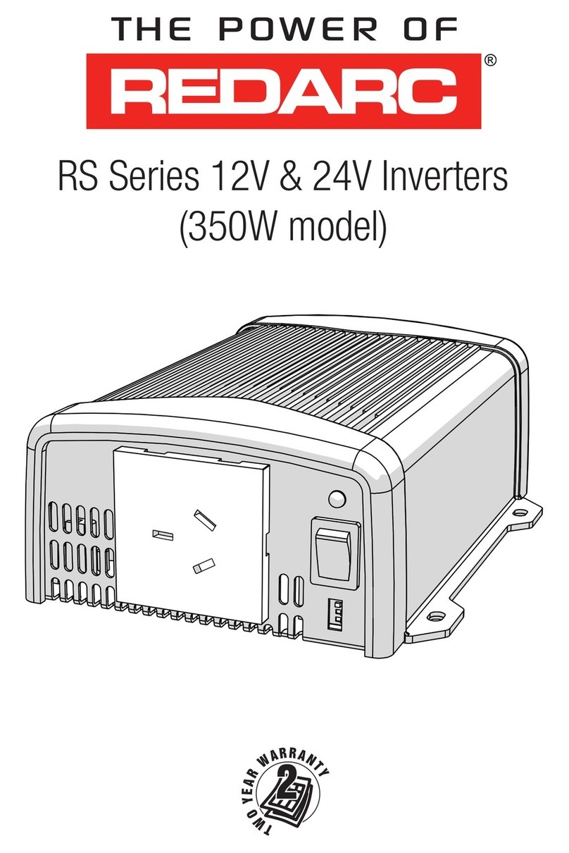
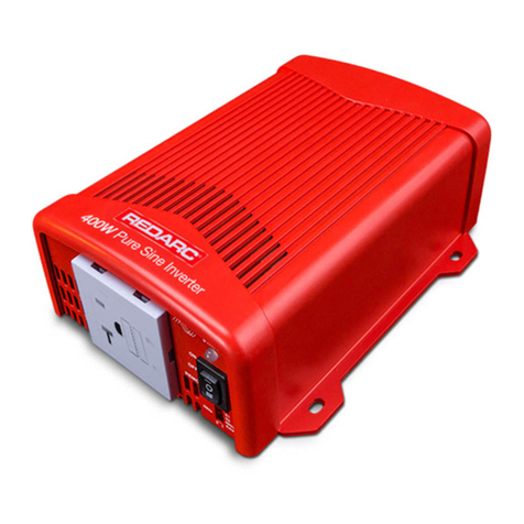
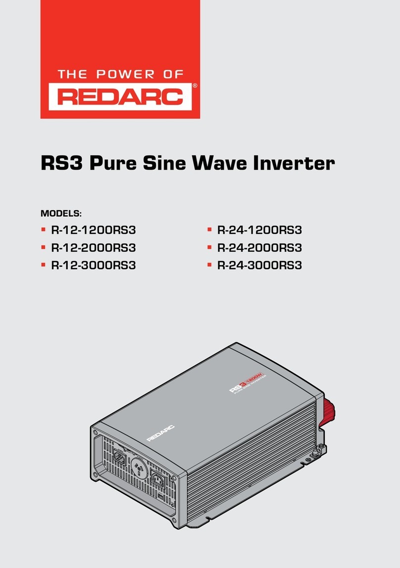
Redarc RS Series User manual

RS Series 12V Inverters
R-12-1000RS-NA
R-12-1500RS-NA
R-12-2000RS-NA
R-12-3000RS-NA

22
RS SERIES INVERTERS
REDARC Pure Sine Wave Inverters produce a pure sine wave output. This means that the power output
from a REDARC Pure Sine Wave Inverter is not only the same as the mains supply, it’s often better.
The R-12-1000RS-NA and R-12-1500RS-NA are compliant for residential and industrial applications
whereas the R-12-2000RS-NA and R-12-3000RS-NA are compliant for industrial applications only.
WARNINGS AND SAFETY INSTRUCTIONS
SAVE THESE INSTRUCTIONS — THIS MANUAL CONTAINS IMPORTANT SAFETY INSTRUCTIONS FOR THE REDARC RS
SERIES PURE SINE WAVE INVERTERS.
DO NOT operate the Inverter unless you have read and understood this manual and the inverter is
installed as per these installation instructions. REDARC recommends that the Inverter be installed by a
suitably qualified person.
WARNING
RISK OF ELECTRICAL SHOCK. DO NOT DISASSEMBLE
THE INVERTER — THE INTERNAL CIRCUITRY CONTAINS
HAZARDOUS VOLTAGES. ATTEMPTING TO SERVICE THE
UNIT YOURSELF MAY RESULT IN ELECTRIC SHOCK OR
FIRE AND WILL VOID THE UNIT WARRANTY.
RISK OF ELECTRICAL SHOCK. DO NOT EXPOSE THE
INVERTER TO RAIN, SNOW, SPRAY, BILGE OR DUST.
DOING SO MAY RESULT IN DAMAGE TO THE INVERTER
OR OTHER APPLIANCES INSTALLED IN THE SYSTEM OR
RESULT IN ELECTRIC SHOCK OR FIRE.
RISK OF ELECTRICAL SHOCK. OPERATION OF THE
INVERTER WITHOUT A PROPER AND RELIABLE GROUND
CONNECTION MAY RESULT IN AN ELECTRICAL SAFETY
HAZARD. ENSURE PROPER GROUND CONNECTION IS
MADE DURING INSTALLATION AND IS MAINTAINED.
FOR FIXED AND/OR TRANSPORTABLE (VEHICLE)
INSTALLATIONS, INSTALL ACCORDING TO THE
APPROPRIATE CODES AND STANDARDS IN USERS
REGION. IF GROUNDING PATH BREAKS AT ANY POINT,
USER IS AT RISK OF SHOCK OR ELECTROCUTION.
RISK OF ELECTRICAL SHOCK. ALL ELECTRICAL WORK
MUST BE PERFORMED IN ACCORDANCE WITH LOCAL
AND NATIONAL CODES, STANDARDS AND WIRING
RULES. INSTALLATION MUST BE PERFORMED BY
QUALIFIED PERSONAL WHO MEET ALL LOCAL AND
GOVERNMENTAL CODE REQUIREMENTS FOR LICENSING
AND TRAINING FOR THE INSTALLATION, MAINTENANCE
AND CONNECTION OF ELECTRICAL POWER SYSTEMS.
SAFETY REGULATIONS RELEVANT TO THE INSTALLATION
AND USE LOCATION SHALL BE FOLLOWED DURING
INSTALLATION, OPERATION AND MAINTENANCE OF THE
INVERTER, IMPROPER OPERATION MAY HAVE A RISK OF
ELECTRIC SHOCK, FIRE OR DAMAGE TO EQUIPMENT AND
PROPERTY.
FIRE HAZARD. ENSURE GROUND, AC AND DC CABLE
SIZES CONFORM TO LOCAL AND NATIONAL STANDARDS
AND WIRING CODES.
RISK OF ELECTRICAL SHOCK AND FIRE. BEFORE
PROCEEDING, CAREFULLY CHECK THAT THE INVERTER
IS NOT CONNECTED TO ANY BATTERIES AND THAT ALL
WIRING IS DISCONNECTED FROM ANY ELECTRICAL
SOURCES.
RISK OF ELECTRIC SHOCK WHEN REMOVING THE COVER
FOR SERVICING, INTERNAL HEAT-SINKS ARE NOT
BONDED TO GROUND, TEST BEFORE TOUCHING
DO NOT CONNECT THE OUTPUT TERMINALS OF THE
INVERTER TO AN INCOMING AC SOURCE.
CAUTION
1. This appliance is not intended for use by
persons (including children) with reduced
physical, sensory or mental capabilities, or lack
of experience and knowledge, unless they are
supervised or have been instructed on how to
use the appliance by a person responsible for
their safety. Children should be supervised to
ensure that they do not play with the appliance.
2. Do not operate the inverter with damaged or
substandard wiring. Selecting the wrong cable
or fuse size could result in harm to the installer
or user and/or damage to the inverter or other
appliances installed in the system. The installer
is responsible for ensuring that the correct
cable and fuse sizes are used when installing
this inverter. Refer to Section 2.2.4 (page 19)
for more information.
INST115–4 EN

3
WARNINGS AND SAFETY INSTRUCTIONS
3. Ensure that all the DC connections are tight — torque between 9to10 ftlbf (11.7to13Nm). Loose
connections could result in overheating and can be a potential hazard.
4. Some components in the inverter can cause arcs and sparks. Do not put batteries, flammable
materials, or anything that should be ignition-protected around the inverter. Doing so may result in fire
or explosion. Be extra cautious so as to reduce the risk of dropping a metal tool onto a vehicle battery.
Doing so might cause the battery to spark or might short-circuit the battery or other electrical parts
that may cause an explosion.
5. Remove personal metal items such as rings, bracelets, necklaces, and watches when working with a
battery. A battery can produce a short-circuit current high enough to weld a ring or the like to metal,
causing a severe burn.
6. If battery acid contacts your skin or clothing, remove the affected clothing and wash the affected area
of your skin immediately with soap and water. If battery acid enters your eye, immediately flood the
eye with running cold water for at least 10 minutes and seek medical assistance immediately.
7. NEVER smoke or allow a spark or flame in the vicinity of a battery. This may cause the battery to
explode.
8. Batteries are capable of providing very large currents in the case of a short circuit. A fuse must be
installed on the positive supply cable as close as practical to the battery. Failure to do so provides
inadequate protection against fire in the case of a short circuit. Only use high quality copper cable and
keep the cable length short, refer to Section 2.2.4 (page 19) for more information.
NOTICE
• Upon receipt, examine the box for damage. If you have found any damage on the box please notify the
company you purchased this unit from.
• Install the inverter in a well-ventilated area with reasonable clearance. Do not install the inverter in a
zero-clearance compartment or obstruct the ventilation openings. Doing so may result in the inverter
overheating and ultimately damage the inverter.
• Reverse Polarity connection will blow the internal fuse and may damage the inverter permanently and
will void warranty.
• Do not operate appliances that may feed power back into the inverter. Damage to the inverter may
occur as a result.
• Ensure that the frequency output of the inverter matches the frequency requirements of all
appliances and equipment to be used with the inverter. Attempting to use appliances that requires
an AC frequency different to the inverter output may result in damage to your appliances. Output AC
frequency is dip switch selectable, see Section 2.1.3 (page 14).
• All RS Series Inverters are suitable for indoor use only.
• The direction of fan air flow must be horizontal.

4
CONTENTS
RS SERIES INVERTERS 2
WARNINGS AND SAFETY INSTRUCTIONS 2
1 INTRODUCTION 5
1.1 Specifications ��������������������������������������������������������������������������������������������������������������5
1.2 Voltage and Temperature Performance����������������������������������������������������������������������������9
1.3 Dimensions����������������������������������������������������������������������������������������������������������������10
2 USER GUIDE 11
2.1 Front Panel Operation��������������������������������������������������������������������������������������������������11
2.1.1 Main Switch ����������������������������������������������������������������������������������������������������������������12
2.1.2 Indicator LED���������������������������������������������������������������������������������������������������������������12
2.1.3 Function Switch �����������������������������������������������������������������������������������������������������������14
2.1.4 Power Saving Load Adjustment ���������������������������������������������������������������������������������������15
2.1.5 TRC Port (RJ45) �����������������������������������������������������������������������������������������������������������15
2.1.6 AC Output Interface ������������������������������������������������������������������������������������������������������ 16
2.2 Rear Panel Operation ��������������������������������������������������������������������������������������������������17
2.2.1 Remote Port (RJ11)�������������������������������������������������������������������������������������������������������18
2.2.2 Remote Control Green Terminal ��������������������������������������������������������������������������������������18
2.2.3 Chassis Ground������������������������������������������������������������������������������������������������������������19
2.2.4 DC Input Connection �����������������������������������������������������������������������������������������������������19
3 INSTALLATION 20
3.1 Mounting�������������������������������������������������������������������������������������������������������������������20
3.2 Ventilation Fan �����������������������������������������������������������������������������������������������������������20
3.3 Safety Before Installing DC Wiring Connections��������������������������������������������������������������21
3.3.1 Loads Are Disconnected ������������������������������������������������������������������������������������������������21
3.3.2 Check Cable and Fuse size���������������������������������������������������������������������������������������������21
3.4 Chassis Ground Connection �����������������������������������������������������������������������������������������22
3.5 DC Wiring Connections������������������������������������������������������������������������������������������������23
3.6 AC Safety Grounding ���������������������������������������������������������������������������������������������������24
3.7 Turning The Inverter On����������������������������������������������������������������������������������������������� 24
3.7.1 Switch Controls������������������������������������������������������������������������������������������������������������ 24
3.7.2 LEDs and Possible Issues ����������������������������������������������������������������������������������������������24
3.8 Connecting AC ����������������������������������������������������������������������������������������������������������� 25
3.9 Maintenance��������������������������������������������������������������������������������������������������������������25

5
1 INTRODUCTION
1.1 Specifications
Model: R-12-1000RS-NA
Input
Characteristics
Max. Rated Input Current 105A
Voltage 12V DC
Over-Voltage Protection 16.5±0.3V DC
Under-Voltage Protection 10.5±0.3V DC
Voltage Range 10.5~16.5V DC
No Load Current ≤1.5A @ 12V DC
Power Saving Mode <0.1A @ 12V DC
Output
Characteristics
Continuous Output Power 1000W (VA) (±3%)
Maximum Output Power (1 min) >1000~1150W (VA) (100%~115%)
Surge Power (<3 sec) <1750W (VA)
Frequency 50/60Hz±0.5% (Dip Switch Selectable)
Output Voltage 100/110/115/120VAC (±5% )
(Dip Switch Selectable)
Efficiency Max 92%
Short-Circuit Protection 1 Sec Shutdown, Restart to Recover
Output Waveform(1) Pure Sine Wave (THD<5% @ Normal Load)
Signal and
Control
Remote Controller Panel Input REMOTE-RS (optional)
LED Indicator Red/Orange/Green LED
Dry Contact Terminal By a relay
Remote Control Terminal 6-port Green terminal (for inverter ON/OFF)
Protection
Input Protection(2) Over/Under Voltage, Reverse Polarity
(Internal Fuse)
AC Output Protection Short-Circuit, Overload
Others Over/Under Temperature Protection (by heat
sink) Temperature 176°F (80°C) /−4°F (−20°C)
Environment
Operating Temp. −4~104°F — Derates to 140°F
(–20~40°C — Derates to 60°C)
Storage Temp. –22~158°F (−30~70°C)
Storage Temp. and Humidity 10~95% RH
Safety and EMC Safety Standards UL 458, C22.2 No. 107.1
EMC Standards(3) FCC Class B, CAN ICES-003 (B)/NMB-003(B)
Weight 7.2 lb (3.3kg)
Cooling Temperature and Load Controlled cooling Fan
Dimensions (W×H×D) 7.9"×3.3"×14.7" (200×83×372mm)
(1) Normal load condition: Vin=12.5V/25V/50V, Vo=100/110/115/120 VAC 80% load (PF=1.0)
(2) Reverse polarity connection can blow the internal fuse and may damage the inverter permanently.
(3) Refer to page 26 for compliance information.

6
1 INTRODUCTION
Model: R-12-1500RS-NA
Input
Characteristics
Max. Rated Input Current 157A
Voltage 12V DC
Over-Voltage Protection 16.5±0.3V DC
Under-Voltage Protection 10.5±0.3V DC
Voltage Range 10.5~16.5V DC
No Load Current ≤1.8A@12V DC
Power Saving Mode <0.1A@12V DC
Output
Characteristics
Continuous Output Power 1500W (VA) (±3%)
Maximum Output Power (1 min) >1500~1730W (VA) (100%~115%)
Surge Power (<3 sec) <2650W (VA)
Frequency 50/60Hz±0.5% (Dip Switch Selectable)
Output Voltage 100/110/115/120VAC (±5%)
(Dip Switch Selectable)
Efficiency Max 91%
Short-Circuit Protection 1 Sec Shutdown, restart to recover
Output Waveform(1) Pure Sine Wave (THD<5% @ Normal Load)
Signal and
Control
Remote Controller Panel Input REMOTE-RS (optional)
LED Indicator Red/Orange/Green LED
Dry Contact Terminal By a relay
Remote Control Terminal 6-port Green terminal (for inverter ON/OFF)
Protection
Input Protection(2) Over/Under Voltage, Reverse Polarity
(Internal Fuse)
AC Output Protection Short-Circuit, Overload
Others Over/Under Temperature Protection (by Heat
sink Temperature 176°F (80°C)/–4°F (–20°C))
Environment
Operating Temp. –4~104°F — Derates to 140°F)
(–20~40°C — Derates to 60°C)
Storage Temp. –22~158°F (–30~70°C)
Storage Temp. and Humidity 10~95% RH
Safety and
EMC
Safety Standards UL 458, C22.2 No. 107.1
EMC Standards(3) FCC Class B, CAN ICES-003 (B)/NMB-003(B)
Weight 9.7 lb (4.4kg)
Cooling Temperature and Load Controlled cooling Fan
Dimensions (W×H×D) 9.8"×3.3"×16.6" (248×83×421mm)
(1) Normal load condition: Vin=12.5V/25V/50V, Vo=100/110/115/120 VAC 80% load (PF=1.0)
(2) Reverse polarity connection can blow the internal fuse and may damage the inverter permanently.
(3) Refer to page 26 for compliance information.

7
1 INTRODUCTION
Model: R-12-2000RS-NA
Input
Characteristics
Max. Rated Input Current 209A
Voltage 12V DC
Over-Voltage Protection 16.5±0.3V DC
Under-Voltage Protection 10.5±0.3V DC
Voltage Range 10.5~16.5V DC
No Load Current ≤1.8A @ 12V DC
Power Saving Mode <0.1A @ 12V DC
Output
Characteristics
Continuous Output Power 2000W (VA) (±3%)
Maximum Output Power (1 min) >2000~2300W (VA) (100%~115%)
Surge Power (<3 sec) <3500W (VA)
Frequency 50/60Hz±0.5% (Dip Switch Selectable)
Output Voltage 100/110/115/120VAC (±5%)
(Dip Switch Selectable)
Efficiency Max 92%
Short-Circuit Protection 1 Sec Shutdown
Output Waveform(1) Pure Sine Wave (THD<5% @ Normal Load)
Signal and
Control
Remote Controller Panel Input REMOTE-RS (optional)
LED Indicator Red/Orange/Green LED
Dry Contact Terminal By a relay
Remote Control Terminal 6-port Green terminal (for inverter ON/OFF)
Protection
Input Protection(2) Over/Under Voltage, Reverse Polarity
(Internal Fuse)
AC Output Protection Short-Circuit, Overload
Others Over/Under Temperature Protection (by Heat
sink) Temperature 176°F (80°C)/–4°F (–20°C))
Environment
Operating Temp. –4~104°F — Derates to 140°F
(–20~40°C — Derates to 60°C)
Storage Temp. –22~158°F (–30~70°C)
Storage Temp. and Humidity 10~95% RH
Safety and
EMC
Safety Standards UL 458, C22.2 No. 107.1
EMC Standards(3) FCC Class A, CAN ICES-003 (A)/NMB-003(A)
Weight 11.6 lb (5.2kg)
Cooling Temperature and Load Controlled cooling Fan
Dimensions (W×H×D) 9.8"×3.3"×17.4" (248×83×443mm)
(1) Normal load condition: Vin=12.5V/25V/50V, Vo=100/110/115/120 VAC 80% load (PF=1.0)
(2) Reverse polarity connection can blow the internal fuse and may damage the inverter permanently.
(3) Refer to page 26 for compliance information.

8
1 INTRODUCTION
Model: R-12-3000RS-NA
Input
Characteristics
Max. Rated Input Current 318A
Voltage 12V DC
Over-Voltage Protection 16.5±0.3V DC
Under-Voltage Protection 10.5±0.3V DC
Voltage Range 10.5~16.5V DC
No Load Current ≤3.8A @ 12V DC
Power Saving Mode <0.4A @ 12V DC
Output
Characteristics
Continuous Output Power 3000W (VA) (±3%)
Maximum Output Power (1 min) >3000~3450W (VA) (100%~115%)
Surge Power (<1 sec) <6000W (VA)
Frequency 50/60Hz±0.5% (Dip Switch Selectable)
Output Voltage 100/110/115/120VAC (±5%)
(Dip Switch Selectable)
Efficiency Max 90%
Short-Circuit Protection 1 Sec Shutdown
Output Waveform(1) Pure Sine Wave (THD<5% @ Normal Load)
Signal and
Control
Remote Controller Panel Input REMOTE-RS (optional)
LED Indicator Red/Orange/Green LED
Dry Contact Terminal By a relay
Remote Control Terminal 6-port Green terminal (for inverter ON/OFF)
Protection
Input Protection(2) Over/Under Voltage, Reverse Polarity
(Internal Fuse)
AC Output Protection Short-Circuit, Overload
Others Over/Under Temperature Protection (by Heat
sink Temperature 176°F (80°C)/–4°F (–20°C))
Environment
Operating Temp. –4~104°F — Derates to 140°F
(–20~40°C — Derates to 60°C)
Storage Temp. –22~158°F (–30~70°C)
Storage Temp. and Humidity 10~95%RH
Safety and EMC Safety Standards(3) UL 458 (provided used with approved
GFCI connector) C22.2 No. 107.1
EMC Standards(4) FCC Class A, CAN ICES-003 (A)/NMB-003(A)
Weight 18 lb (8.2kg)
Cooling Temperature and Load Controlled cooling Fan
Dimensions (W×H×D) 10.1"×6.2"×17.4" (255×158×442mm)
(1) Normal load condition: Vin=12.5V/25V/50V, Vo=100/110/115/120 VAC 80% load (PF=1.0)
(2) Reverse polarity connection can blow the internal fuse and may damage the inverter permanently.
(3) Ground Fault Circuit Interrupter (GFCI) see 2.1.6 on (page 16).
(4) Refer to page 26 for compliance information.

9
1 INTRODUCTION
1.2 Voltage and Temperature Performance
Voltage (V)
1 Sec
1 Sec
Continuous
1 Min
10.5 V
0%
100%
115%
(3000 W) 200%
16 V 16.5 V
Power (W)
175%
(1000 W
1500 W
2000 W)
FIGURE 1.2.1: Output Power vs. Input Voltage (1000–3000W)
Temperature ºF (ºC)
1 Sec
Continuous
Output Power
1 Min
−4°F
(−20 °C)
0%
100%
115%
(3000 W) 200%
40%
32 °F
(0 °C)
104 °F
(40°C)
140°F
(60°C)
Power (W)
175%
(1000 W
1500 W
2000 W)
FIGURE 1.2.2: Output Power vs. Input Air Temperature (1000–3000W)

10
1 INTRODUCTION
1.3 Dimensions
DC Input Side
DC Input Side
D
1000 W 1500 / 2000 / 3000 W
E
A
B
C
E
A
D
B
C
F
F
G
A B C D E F G
1000W 14.65"
(372mm)
2.7"
(69mm)
7.7"
(196mm)
7.9"
(200mm)
0.3"
(7.0mm)
3.3"
(83mm)
7.25"
(184mm)
1500W 16.6"
(421mm)
3.6"
(92mm)
7.7"
(196mm)
9.8"
(248mm)
0.3"
(7.0mm)
3.3"
(83mm)
9.1"
(232mm)
2000W 17.4"
(443mm)
4.1"
(103mm)
7.7"
(196mm)
9.8"
(248mm)
0.3"
(7.0mm)
3.3"
(83mm)
9.1"
(232mm)
3000W 17.4"
(442mm)
4.1"
(103mm)
7.7"
(196mm)
10.0"
(255mm)
0.3"
(7.0mm)
6.2"
(158mm)
9.4"
(239mm)

11
2 USER GUIDE
2.1 Front Panel Operation
WARNING: RISK OF ELECTRICAL SHOCK. DO NOT DISASSEMBLE THE INVERTER — THE INTERNAL CIRCUITRY
CONTAINS HAZARDOUS VOLTAGES. ATTEMPTING TO SERVICE THE UNIT YOURSELF MAY RESULT IN ELECTRIC SHOCK
OR FIRE AND WILL VOID THE UNIT WARRANTY.
3
2
5
1
6
4
FIGURE 2.1.1: 1000W Models
3
2
5
1
6
4
FIGURE 2.1.2: 1500/2000W Models
4
3
2
5
1
6
FIGURE 2.1.3: 3000W Models
1000W 1500W 2000W 3000W
1 Main Switch
2 Indicator LEDs
3 Function Switch
4Power Save Adjustment
5 TRC Port (RJ45)
61000W/1500W/2000W 3000W
AC Output Socket AC Output Terminals

12
2 USER GUIDE
2.1.1 Main Switch
The 3 stage switch is for turning the AC mains output to either ON, OFF or selecting the Remote mode.
When setting the power switch to the first ON position or the second ON position (only to be used when
operating the inverter through the REMOTE-RS inverter remote) the LEDs will glow GREEN.
After setting the power switch to the OFF position the inverter will stop and the LEDs will turn off.
2.1.2 Indicator LED
Input Voltage Level:
LED Status 12V Models
Red <11.0V
Orange 11.0~11.5V
Green 11.5~15.0V
Orange 15.0~15.5V
Red > 15.5V
Output Load Level:
LED Status Green Orange Red
1000W 0~1000W 1000~1150W >1150W
1500W 0~1500W 1500~1725W >1725W
2000W 0~2000W 2000~2300W >2300W
3000W 0~3000W 3000~3450W >3450W
1
2

13
2 USER GUIDE
Inverter Status and fault conditions:
Status LED Status Remedies
Power On/Normal Green
Over Current / Over Load
(AC output short and overload) Red
Reduce Load
If output does not recover once load has been
reduced to within specification, try turning
the inverter's power switch on and off again.
Over Voltage Protection
(Input DC voltage over spec)
Recovery Points: 14.5V (12V Models)
Red Red RedRed Red Red
Check input voltage
Reduce input voltage to meet
the inverter's specification.
Under Voltage Protection
(Input DC voltage under spec)
Recovery Points: 12.5V (12V Models)
Red Red Red
Check input voltage and recharge battery.
Check all input connections and cables. Once
input conditions are within spec, try turning
power switch off and on again.
Device Startup process abnormal Orange
Under Temperature
(Heatsink temp. under −4°F (−20°C))
Recovery point: >32°F (0°C)
Orange Orange Orange Orange Orange Orange
Reduce load
If output does not recover once
load has been reduced to within
specification, try turning off and on
again using the power switch.
Over Temperature
(Heatsink temp. over 176°F (80°C))
Recovery point: <60°F (140°C)
Orange Orange Orange
Improve ventilation
Make sure ventilation openings in inverter
are not obstructed. Reduce ambient
temperature.

14
2 USER GUIDE
2.1.3 Function Switch
12
S1
3 4
ON
OFF
FIGURE 2.1.3.1: Dip Switch ON/OFF Positions
Input Voltage Level:
Dip Switch Function
Switch 1 Output Voltage Select
Swtich 2
Switch 3 Frequency Select
Switch 4 Power Saving mode Select
Output Voltage Selection (Switches 1 and 2):
Output Voltage Switch 1 Switch 2
100V OFF OFF
110V ON OFF
115V OFF ON
120V ON ON
Output Frequency (Switch 3):
Frequency (Hz) Switch 3
50Hz OFF
60Hz ON
Power Saving mode Select:
Power Saving Function Switch 4
Power Saving OFF OFF
Power Saving ON ON
3

15
2 USER GUIDE
2.1.4 Power Saving Load Adjustment
FIGURE 2.1.4.1: Power Saving Load Adjustment
The user can adjust the potentiometer to set the input sleep and wake-up thresholds according to the
load applied. The setting range is shown below:
Model
Minimum
(Potentiometer turned fully
anti-clockwise)
Maximum
(Potentiometer turned fully
clockwise)
Sleep Power Wake Up Power Sleep Power Wake Up Power
1000/1500/2000W <20W >40W <110W >160W
3000W <40W >60W <240W >280W
Potentiometer Rotation
Wake Up Power
Sleep Power
Anti-Clockwise
160
40
110
20
Clockwise
Power (W)
1000−2000 W Models
(min) (max)
Potentiometer Rotation
Wake Up Power
Sleep Power
Anti-Clockwise
280
60
240
40
Clockwise
Power (W)
3000 W Models
(min) (max)
2.1.5 TRC Port (RJ45)
Not currently used.
4
5

16
2 USER GUIDE
2.1.6 AC Output Interface
WARNING
ALL ELECTRICAL WORK MUST BE PERFORMED IN ACCORDANCE WITH THE LOCAL AND NATIONAL ELECTRICAL
CODES. THESE INSTRUCTIONS ARE FOR USE BY QUALIFIED PERSONNEL WHO MEET ALL LOCAL AND GOVERNMENT
CODE REQUIREMENTS FOR LICENSING AND TRAINING FOR THE INSTALLATION OF ELECTRICAL POWER SYSTEMS
WITH AC AND DC VOLTAGE UP TO 600 VOLTS. INSTALLATION, MAINTENANCE AND CONNECTION OF INVERTERS
MUST BE PERFORMED BY QUALIFIED PERSONNEL, IN COMPLIANCE WITH LOCAL ELECTRICAL STANDARDS AND
CODES, WIRING RULES AND THE REQUIREMENTS OF LOCAL POWER AUTHORITIES AND/OR COMPANIES. SAFETY
REGULATIONS RELEVANT TO THE LOCATION SHALL BE FOLLOWED DURING INSTALLATION, OPERATION AND
MAINTENANCE
IMPROPER OPERATION MAY HAVE A RISK OF ELECTRIC SHOCK OR DAMAGE TO EQUIPMENT AND PROPERTY.
L
N
FG
FIGURE 2.1.6.1: AC Output Interface for
1000/1500/2000W Models
FIGURE 2.1.6.2: Standard Hard Wire Socket for
3000W Models
R-12-3000RS-NA Output Interface
Terminal Wire color Wire length/gauge
AC terminal Line (L) Black Within 6 feet/AWG8
Neutral (N) White
FG (Ground) Green / Yellow or Bare
copper
26~32 feet / AWG#
10~8
In order for R-12-3000RS-NA to be UL 458 compliant it requires to be used with one or more of the
following GFCI connectors:
• HUBBELL INC WIRING DEVICE DIV, Type GF20 and GFRST20 Rated 125V, 20A
• COOPER WIRING DEVICES, Type VGF20 and SGF20. Rated 125V, 20A
• LEVITION MFG CO INC, Type 7899-W and GFNT2. Rated 125V, 20A
• PASS AND SEYMOUR INC, Type 2097. Rated 125V, 20A
Additional breakers suitable for 20A branch circuit protection shall be provided for the GFCI receptacles.
Branch rated overcurrent protection for the AC output circuit is to be provided at the time of installation
6

17
2 USER GUIDE
2.2 Rear Panel Operation
1
2
3
4
FIGURE 2.2.1: 1000W Models
2 3
1
4 4
FIGURE 2.2.2: 1500W/2000W Models
4 4
1
2
3
FIGURE 2.2.3: 3000W Models
1000W 1500W 2000W 3000W
1Remote Port (RJ11)
2Remote Control Green Terminal
3Chassis Ground
4DC Input Connector

18
2 USER GUIDE
2.2.1 Remote Port (RJ11)
The RS Series inverter can be used with the REMOTE-RS remote controls via RS-232 communication.
To enable, set the main switch on the inverter to the REMOTE position.
Pin Number Signal Description (1)
1 Reserved --
2 GND Same Polarity as Battery Negative
3 RXD RS232 RXD
4 TXD RS232 TXD
5 RMT Remote controller panel (positive)
6 VCC Internal power for remote controller
2.2.2 Remote Control Green Terminal
The remote control green terminal is connected to a Form C relay for fault indication. When a fault occurs,
the relay switches. Fault conditions include Input Under/Over voltage, output short-circuit/overload, Under/
Over temperature.
FIGURE 2.2.2.1: Remote Control Terminal
Pin Number Terminal Description
1Fault relay, Normally Open (16V, 10mA max.)
2Fault relay, Common (16V, 10mA max.)
3Fault relay, Normal Closed (16V, 10mA max.)
4Enable+ (ENB)
5Enable− (ENB)
6Ground (Same polarity as battery negative)
NOTICE
• Before Installing — Make sure that the inverter main switch is at OFF position
• Before using the remote function, make sure the main switch is set to 'REMOTE'
• Use 20 to 24AWG cable to connect the remote control terminals
1
2

19
2 USER GUIDE
ENB
GND
GND
BAT+
BAT–
ENB
ENB
ON:INV.
OFF:INV.
ON
OFF
ON:INV.
OFF:INV.
ON
OFF
+ DC
– POWER
ON:INV.
OFF:INV.
ON
OFF
FIGURE 2.2.2.2: Wiring configurations for Remote Control Green Terminal
2.2.3 Chassis Ground
Use 16 AWG (1.5mm²) or a thicker cable to connect the vehicle earth or chassis ground. Perform this
connection prior to any other connection.
2.2.4 DC Input Connection
Prior to installation:
• The cable and fuse sizes in Table 2.2.4.1 are recommended for connection between supply battery
and inverter. The DC supply cables should be as short as possible and no longer than the values
shown in Table 2.2.4.1.
• The size of the cable should be thick enough to maintain a voltage drop of less than 2% when
carrying the maximum input current. This will help prevent frequent low-input voltage warnings and
shutdown.
TABLE 2.2.4.1: Recommended Fuse and Cable Sizing (12V Install):
Recommended Fuse size
12V Inverter 1000W 1500W 2000W 3000W
Fuse Size 175A 225A 250A 450A
Recommended Fuse Mega Mega Mega Mega
Recommended Cable size AWG (nearest equivalent in mm2)
Cable length
ft (m) 1000W 1500W 2000W 3000W
0–6.6
(0−2)
0 (1/0) 54mm2000 (3/0) 85mm20000 (4/0)* 105mm20000 (4/0)* 120mm2
6.6–9.8
(2−3)
00 (2/0) 68mm2000 (3/0) 85mm20000 (4/0)* 105mm2/
9.8–13.1
(3−4)
/ 0000 (4/0) 105mm20000 (4/0)* 120mm2/
Fuse ratings are suitable for these recommended minimum cable sizes.
High temperature (230°F/110°C) or higher rated cable is required.
3
4

20
3 INSTALLATION
3.1 Mounting
Install the inverter in a well-ventilated area with reasonable clearance, avoid installing the inverter in
a zero-clearance compartment or obstruct the ventilation openings, doing so may result in the inverter
overheating and ultimately damage the inverter.
The power inverter should be used in an environment that meets the following requirements:
1. Dry — Do not allow water to drip on or enter into the inverter. Do not allow moisture to
condense on the inverter.
2. Cool — Ambient air temperature should be between 32°F (0°C) and 104°F (40°C).
3. Safe — Do not install the inverter in a battery compartment or other areas where volatile fumes
may exist, such as fuel storage areas or engine compartments.
4. Ventilated — Keep the inverter at a distance (at least 1" (25mm) away from surrounding objects.
Ensure the vents on the rear and the bottom of the unit are not obstructed.
5. Dust — Do not install the inverter in a dusty environment where the dust can enter into the unit both
when the fan is operating and not operating.
6. Fused – A fuse must be fitted between the battery and the inverter, positioned as close to the
battery as possible.
7. Do not mount the inverter where it will be exposed to the gasses produced by the battery.
These gasses present a risk of explosion and are very corrosive, prolonged exposure may
damage the inverter.
WARNING
RISK OF ELECTRICAL SHOCK. DO NOT EXPOSE THE INVERTER TO RAIN, SNOW, SPRAY, BILGE OR DUST. DOING SO
MAY RESULT IN DAMAGE TO THE INVERTER OR OTHER APPLIANCES INSTALLED IN THE SYSTEM OR RESULT IN
ELECTRIC SHOCK OR FIRE.
RISK OF ELECTRICAL SHOCK. DO NOT DISASSEMBLE THE INVERTER - THE INTERNAL CIRCUITRY CONTAINS
HAZARDOUS VOLTAGES. ATTEMPTING TO SERVICE THE UNIT YOURSELF MAY RESULT IN ELECTRIC SHOCK OR FIRE
AND WILL VOID THE UNIT WARRANTY.
TABLE 3.1.4.1: Recommended Mounting
Horizontal Wall Mount, Base
Down
Horizontal Mount, Base
down/up
Do not mount in a vertical
configuration
3.2 Ventilation Fan
The fan is load and temperature controlled and will operate when the AC Power Consumption and
temperature requires it. The fan will also occasionally come on when no load is connected. Ensure that
the fan is not obstructed and the inverter is at a distance of at least 1" (25mm) from surrounding objects.
Other manuals for RS Series
1
This manual suits for next models
4
Table of contents
Other Redarc Inverter manuals
Popular Inverter manuals by other brands

SMA
SMA SUNNY BOY 3800-US user manual

STIEBEL ELTRON
STIEBEL ELTRON SOKI BASIC Operation and installation

Hitachi
Hitachi L100 Series instruction manual

SolaX Power
SolaX Power X3-Retro Fit Series Quick installation guide

Hitachi
Hitachi SJ100 Series Supplemental sheet

Mitsubishi Electric
Mitsubishi Electric 800 Series instruction manual