Redback® A 4585 Zone Paging System
www.altronics.com.au Redback® Proudly Made In Australia 9
Setup Guide
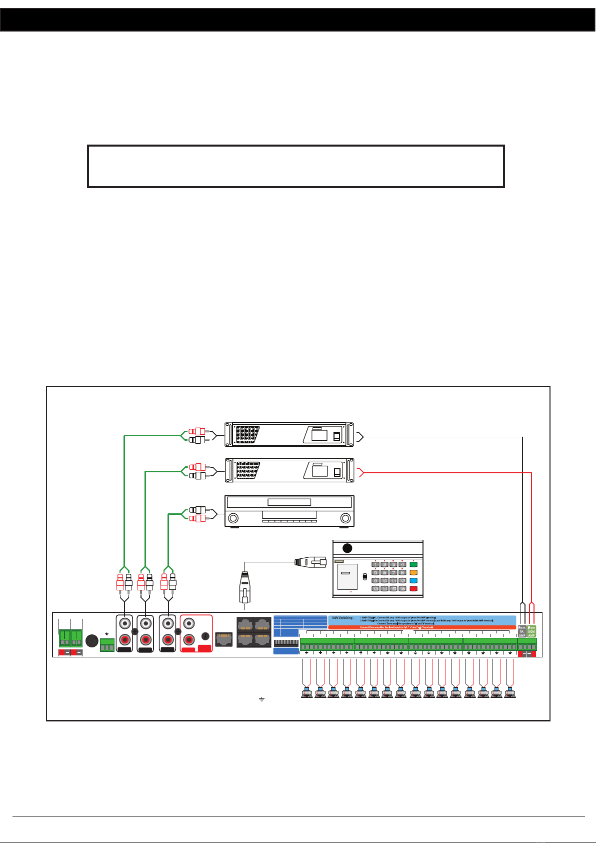
2.2.2 TWO AMPLIFIER 100V LINE SWITCHING
A two amplier system uses dedicated ampliers for both the background music and the PA paging. This setup mutes
background music to only those zones which are being paged.
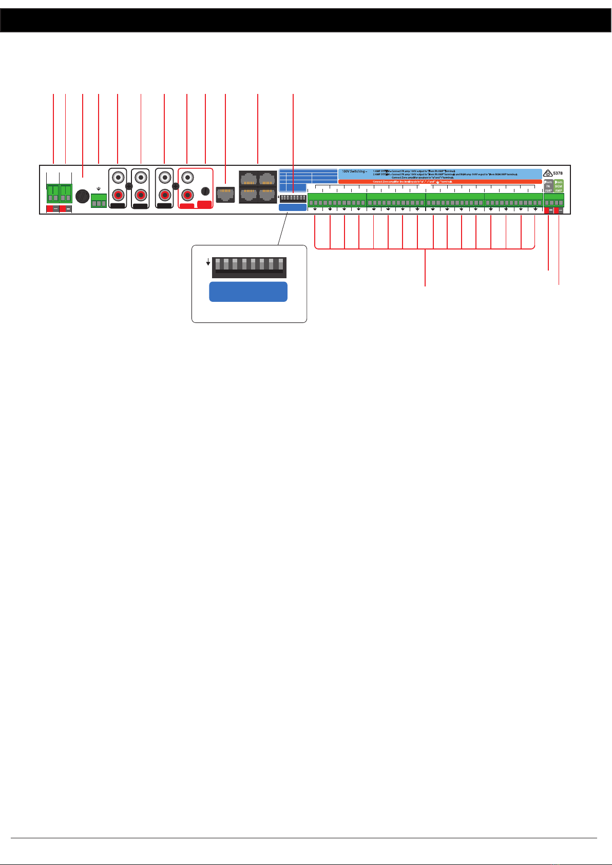
NOTE : Before turning the unit on make sure the dip switches are set correctly.
For two amp switching of 100V speaker levels, Dip switch 1 should be set to “OFF”
and dip switch 2 should be set to “OFF” (see Dip switch settings Fig 1.6)
Each zone requiring background music must be switched “ON” from the “Zone Background Music Selector” switches on
the front of the A 4585. (refer to section 1.4)
A background music source such as a CD player is connected to the BGM input (RCA connectors) on the rear of the
A 4585.
Paging Amplier Connections
The paging amplier audio connection is from the “PA Out” RCA sockets on the rear of the A4585. This is a line level
signal and must be connected to a Line/Aux input on the amplier.
The paging amplier 100V output must be connected to the “From PA AMP” terminals on the rear of the A 4585.
Background Music Amplier Connections
The background music amplier audio connection is from the “BGM Out” RCA sockets on the rear of the A 4585. This is
a line level signal and must be connected to a Line/Aux input on the amplier.
The background music amplier 100V output must be connected to the “From BGM AMP” terminals on the rear of the
A 4585.
The zone 100V speakers are wired to the “+” and “-” terminals only on the rear of the A 4585 as shown in Fig 2.2A.
(Note: the earth connection is not used for 100V switching system. This terminal is used when switching line level signals.)
Fig 2.2
Manufactured in Australia By Altronic Distributors Pty. Ltd.
From
BGM
AMP
L
R
L
R
BGM Out
24V
Switched
Out
N/O
DC FUSE
(1A M205)
From
24V
BATTERY
24V DC
IN
A 4575 Input
N/C
From
PA
AMP
Zones
1 2 3 4 5 6 7 8
1
Paging Stations
34
12
+ -
+ -
2345678910111213141516
100V Switching -
1 AMP SYSTEM - Connect PA amp 100V output to “From PA AMP”Terminals
2 AMP SYSTEM - Connect PA amp 100V output to “From PA AMP” terminals and BGM amp 100V ouput to“From BGM AMP terminals.
Connect Zone amplier speakers to ”+”and “-”terminals.
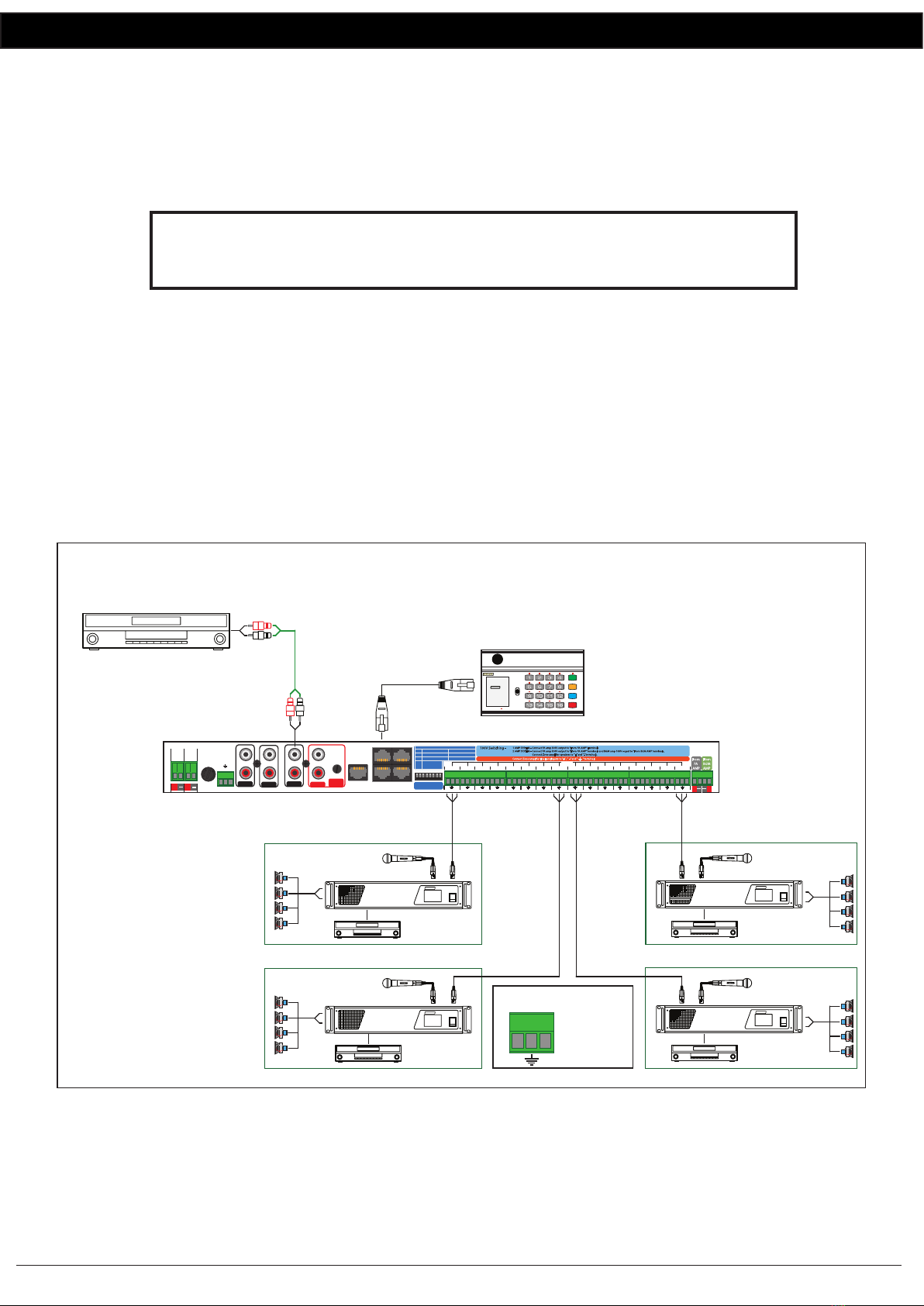
Connect Zone amplier line level inputs to“+” , ” - ” and“ ” terminals.
Preamp Switching -
DIP Switch Settings
SW
1
2
3-8
On O
Single Amp Mode
Not Used
Dual Amp Mode
Line Level Speaker Level
+- +- +- +- +- +- +- +-
+-
+-
+-
+-
+-- +
+
-- +
www.altronics.com.au
++
__
PA Out
BGM Input Evac Input
Evac Vox
Sensitivity
+_
+_
BGM (Background Music Source)
Line Input
100V Output
Connect to
“From PA AMP”
terminals
Two Amplier 100V Line Switching
Speakers to be paged must be tted
with 100V line transformers.
Connect using the “+” and “-”
terminals. (Do not use the “ ” terminal)
Zone
16
1 2 3 4 5 6 7 8
CD
REDBACK
POWER
REDBACK
A 4270 125W
PublicAddress Amplie
PHASE5
100V LINE PAGING AMPLIFIER
A 4586 Paging Console
CAT5 cable
(Max 300 Metres)
Zone
15
Zone
14
Zone
13
Zone
12
Zone
11
Zone
10
Zone
9
Zone
8
Zone
7
Zone
6
Zone
5
Zone
4
Zone
3
Zone
2
Zone
1
Line Input
100V Output
POWER
REDBACK
A 4270 125W
PublicAddress Amplie
PHASE5
100V LINE BACKGROUND MUSIC AMPLIFIER
Store
Recall
All Call
Cancel
A 4586 Communicator
System Busy
Page
Lock On
REDBACK A 4586
8Zone Communicator
Version1.1