www.altronics.com.au Redback® Proudly Made In Australia 7
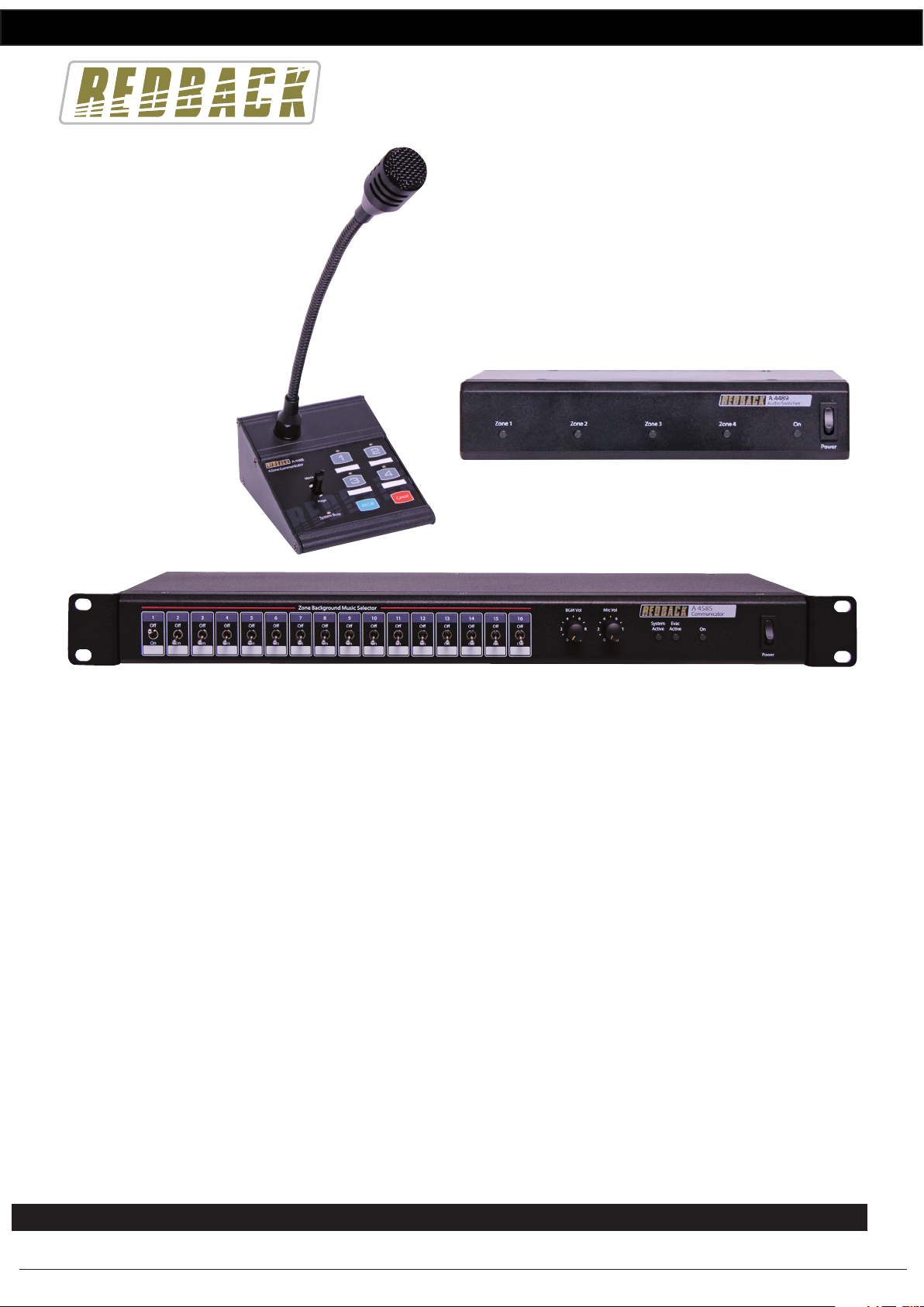
Redback® A 4488 Paging Console
If BGM is active on paging console 1 and paging is to be initiated by this same console then the PTT switch will need to be
moved to the “Page” position. Once the PTT switch is moved off the “BGM” position, then the BGM stops.
Fig 8a and 8b illustrate a typical example of BGM on one console and paging on the other console.
In Fig 8a paging console 1 has zones 1 & 2 selected and the PTT switch moved to the “BGM” position. Background music
is being fed to zones 1 & 2. The LED’s on zones 1 & 2 are illuminated indicating which zones have background
music. Paging console 2 has the PTT switch in the OFF position which means it’s not active and has no visual indication
that the BGM is active to zones 1 & 2.
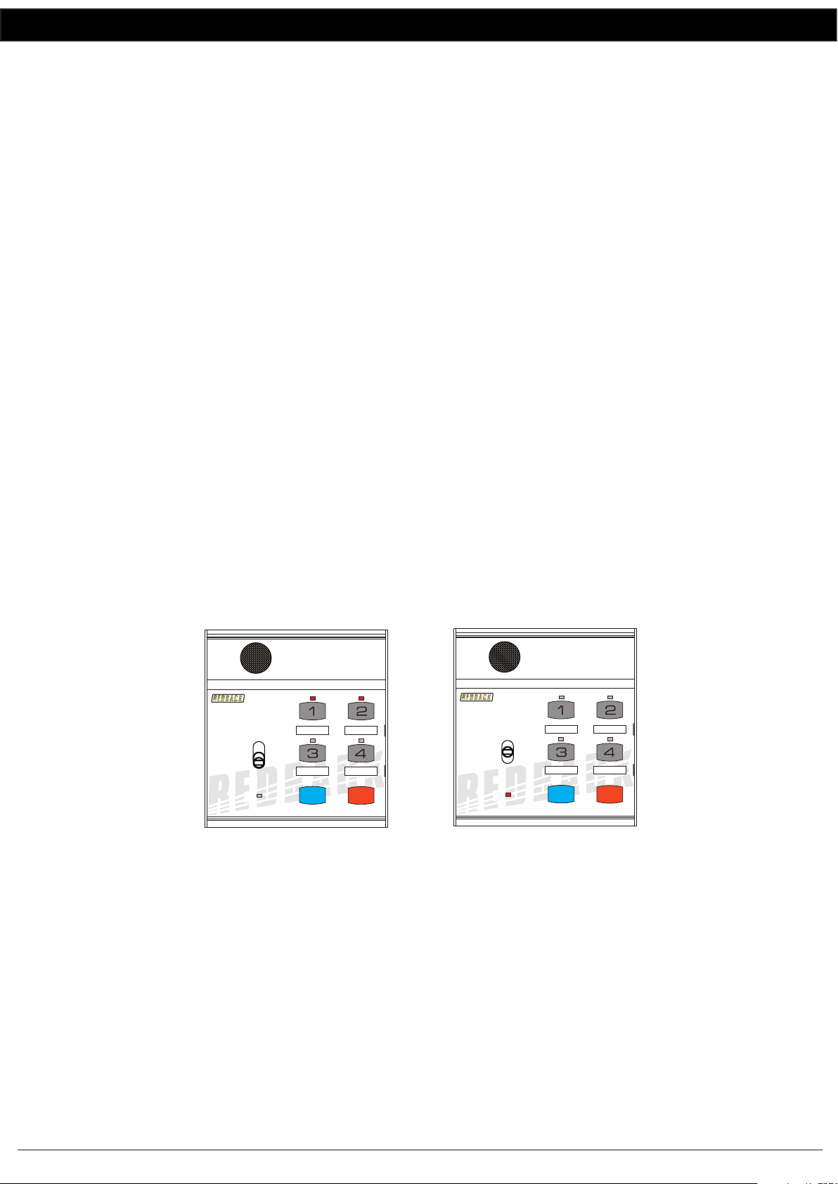
In Fig 8b Paging console 2 has the PTT switch in the “Page” position and zones 3 and 4 are now active for paging.
Paging console 1 still has the PTT switch in the “BGM” position. The LED’s on zones 1 & 2 stay illuminated indicating
which zones have background music. But since console 2 is now paging, console 1 has been over-ridden and the paging
audio is now sent to zones 3 & 4. The system busy led is illuminated on console 1 indicating the system is busy and that
console 1 has now been “Locked Out” until console 2 nishes paging. The background music has been disconnected.
Once console 2 nishes paging the BGM will be re-stored to zones 1 and 2.
Fig 8b
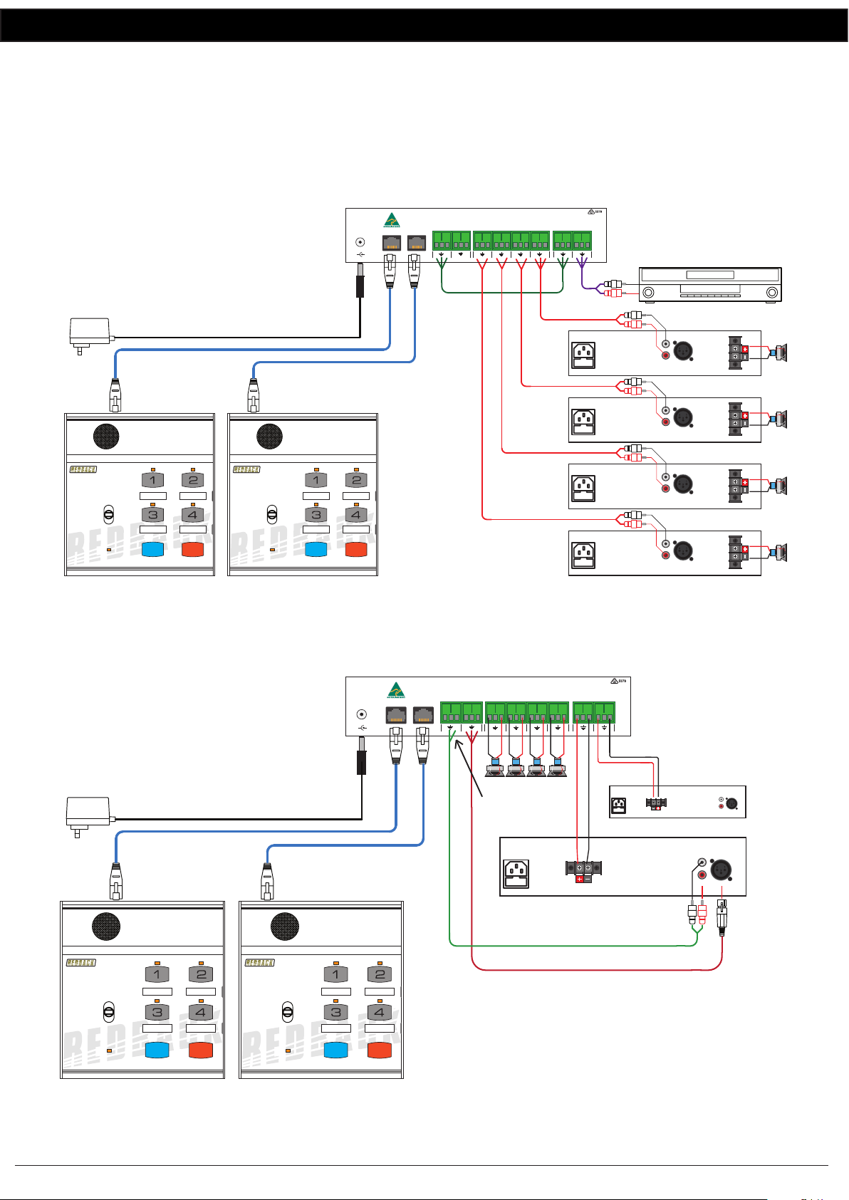
10.0 Connecting the Paging Console/s and the A 4580 Communicator
The Paging console/s and A 4580 Communicator are connected by CAT5e cables with a maximum run distance of 300
metres. This CAT5e cable can be connected to either of the two RJ45 ports provided on the rear of the microphone. A
24V DC power supply rated at a minimum of 1A is required to power the system. Power connection must be made by
Fig 9
Paging console 1 still has
the PTT switch in the“BGM” position.
The LED’s on zones 1 & 2 stay illuminated
indicating which zones have background
music. But since console 2 is paging the
system busy led is illuminated and the
background music has been disconnected.
4 Zone Communicator
System Busy
Page
BGM
All Call Cancel
A 4488
4 Zone Communicator
System Busy
Page
BGM
All Call Cancel
A 4488
Paging console 2 has the
PTT switch in the“Page” position
and zones 3 and 4 are active.
Console 1 has now been over-ridden
and the paging audio is now sent
to zones 3 & 4.
Paging Console 1 Paging Console 2
A 4586 Paging Console
CAT5e cable
(Max 300 Metres)
A 4580 COMMUNICATOR
A 4586 Paging Console
CAT5e cable
(Max 300 Metres)
CAT5e cable
(Max 300 Metres)
CAT5e cable
(Max 300 Metres)
A 4488 Paging Console
PLEASE NOTE : A MAXIMUM OF 4 PAGING CONSOLES CAN BE CONNECTED TO THE A 4580
WITHOUT THE USE OF EXTERNAL POWER SUPPLIES. (AND A MAXIMUM OF 1 PAGING CONSOLE PER PORT)
Manufactured in Australia By Altronic Distributors Pty. Ltd.
From
BGM
AMP
L
R
BGM Out
24V
Switched
Out
From
24V
BATTERY
24V DC
IN
Zone 17-32
From
PA
AMP
Zones
1 2 3 4 5 6 7 8
1/17
34
12
+ -
+ -
2/183/194/205/216/227/238/249/2510/2611/2712/2813/2914/3015/31
16/32
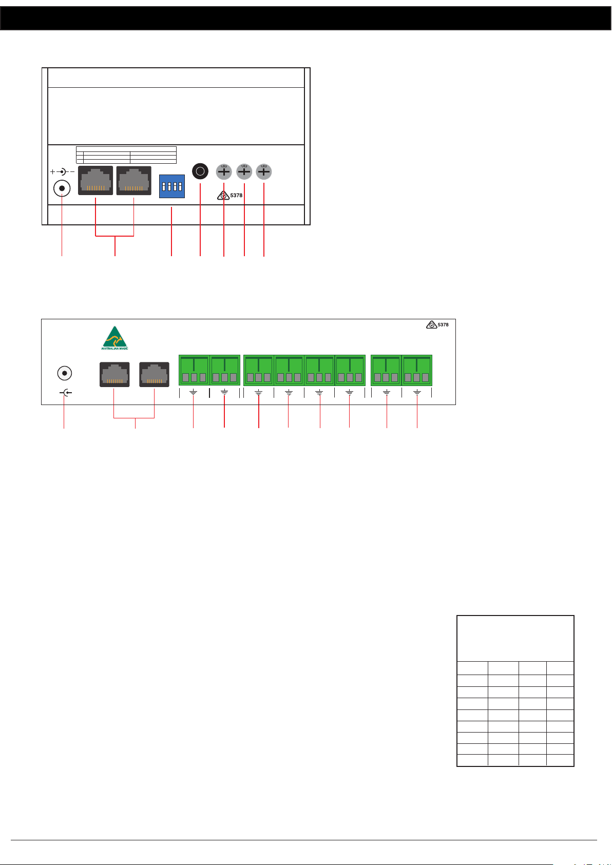
100V Switching - 1 AMP SYSTEM - Connect PA amp 100V output to “From PA AMP”Terminals
2 AMP SYSTEM - Connect PA amp 100V output to “From PA AMP”terminals and BGM amp 100V ouput to “From BGM AMP terminals.
Connect Zone amplier speakers to ”+” and“-”terminals.
Connect Zone amplier line level inputs to“+”, ” - ” and“ ” terminals.
Preamp Switching -
DIP Switch Settings
SW
1
2
4-8
On O
Single Amp Mode
Not Used
Dual Amp Mode
Line Level Speaker Level
N/O
N/C
+-
www.redbackaudio.com.au
+_
PA Out
BGM Input Evac Input
+_
+_
324V Out Trigger
ON-Evac/OFF-Any
L
R
Extender
16GB
Maximum
Micro
SD Card
Evac
Trigger
120mA
Max
To Paging Consoles
(Maximum 500mA per output)
+- +- +- +- +- +- +- +- +- +- +- +- +- +- +-
1 2 3 4 5 6 7 8
Store
Recall
All Call
Cancel
A 4586 Communicator
SystemBusy
Page
Lock On
REDBACK A4586
8Zone Communicator
Version1.1
Store
Recall
All Call
Cancel
A 4586 Communicator
SystemBusy
Page
Lock On
REDBACK A4586
8Zone Communicator
Version1.1
4Zone Communicator
System Busy
Page
BGM
All Call Cancel
A 4488
A 4488 Paging Console
4Zone Communicator
System Busy
Page
BGM
All Call Cancel
A 4488