Simu 9014736 User manual

Présentation
1
Installation
2
FPANNEAU SOLAIRE - 9014736
S.A.S. au capital de 5 000 000 €- Z.I. Les Giranaux - BP71 - 70103 Arc-Les-Gray CEDEX - RCS GRAY B 425 650 090 - SIRET 425 650 090 00011 - n° T.V.A CEE FR 87 425 650 090
5055193A
Lire attentivement cette
notice avant toute utilisation.
1/1
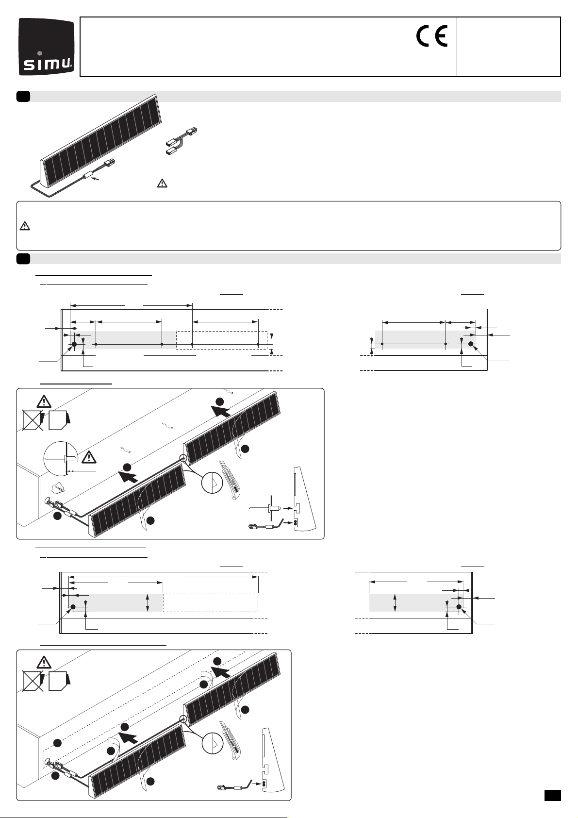
2.2 - Fixation du(des) panneau(x) par collage
2.2a - Perçage du coffre et de la console
Perçage pour panneau situé à gauche du coffre : Perçage pour panneau situé à droite du coffre :
20
15
Ø15
55
500
15
1000
1er panneau 2nd panneau*
20 15
Ø15
55
500
15
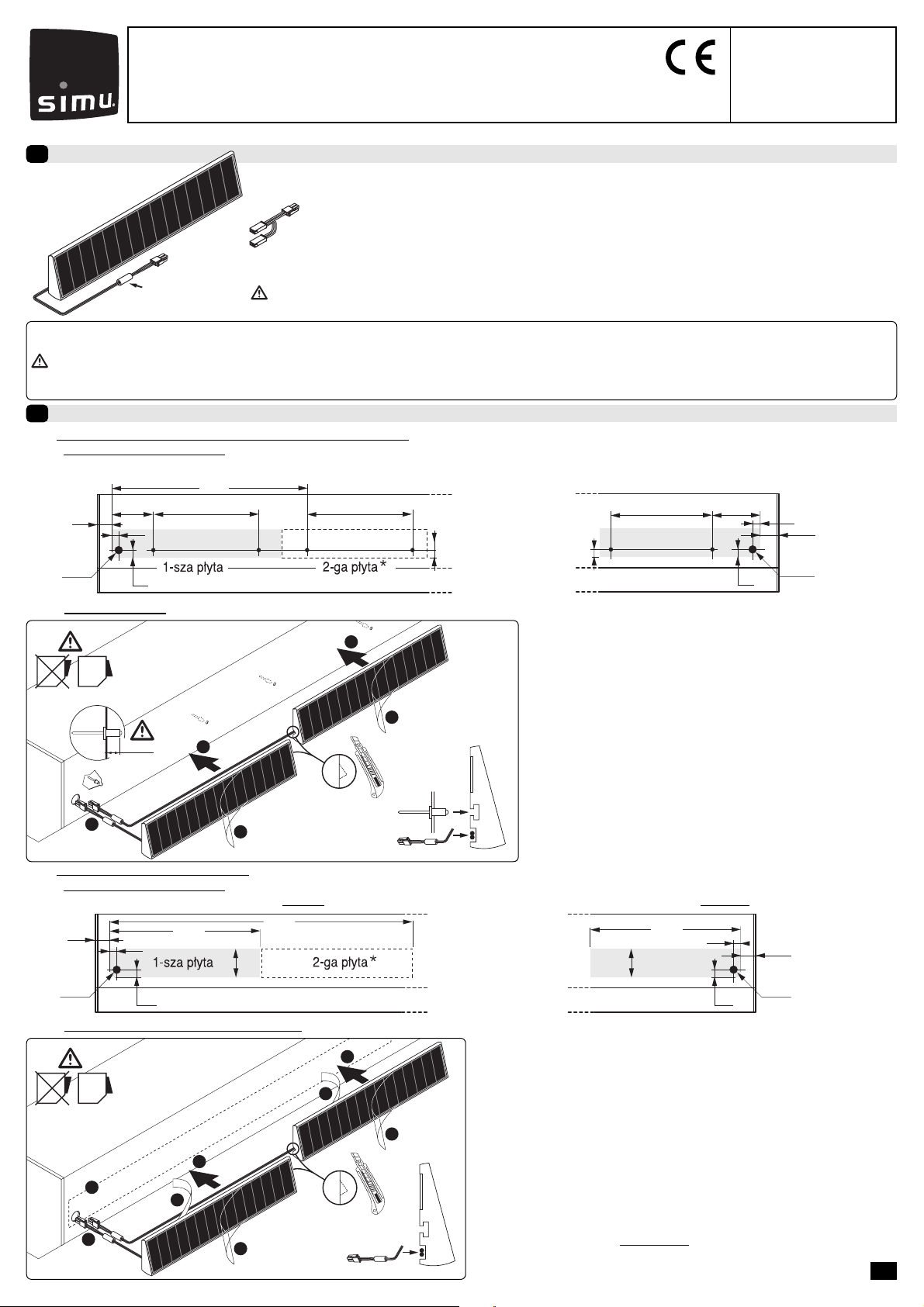
2.1 - Fixation du(des) panneau(x) par rivetage
2.1a - Perçage du coffre et de la console (ATTENTION : ne pas percer le panneau ni son support)
Perçage pour panneau(x) situé(s) à gauche du coffre : Perçage pour panneau situé à droite du coffre :
20
15
Ø15
70 360 360
570
15
14
Ø4,2 Ø4,2 Ø4,2 Ø4,2
1er panneau 2nd panneau*
70360
15 Ø15
Ø4,2 Ø4,2
14
20 15
En transformant l’énergie solaire en énergie électrique, le panneau solaire permet la
charge du pack batterie (réf.:9014734) du système Autosun.
Caractéristiques techniques :
- Intensité délivrée par un panneau (Isc) : 78,6 mA
- Tension délivrée par un panneau (Uoc) : 24,5 V
- Umpp = 18V - Impp = 61,2 mA
- Pour certaines applications deux panneaux solaires peuvent être nécessaires. Voir notice Simu réf.: 5055194.
- Seul le montage avec panneaux positionnés à gauche autorise l’utilisation de 2 panneaux.
- Veillez à ne pas blesser les câbles lors de l’installation. Ebavurer tous les perçages.
- Ne pas apposer sur le panneau solaire de produit pouvant filtrer les rayons du soleil
(ex.: peinture…).
- Les cellules phovoltaïques doivent être maintenues propres (nettoyage à l’eau claire).
- Par temps neigeux, veillez à ne pas laisser s’accumuler la neige sur le panneau.
- Nous recommandons aux utilisateurs de réaliser des essais industriels dans
les conditions exactes de l'application envisagée afin de s'assurer que notre
produit satisfait à ses contraintes. En cas d'incertitude, préférer la solution
par rivetage.
Mousse de protection
Faisceau pour 2 panneaux*
(réf.:5050240A)
2.2b - Préparation du coffre et collage du(des) panneau(x)
Préconisations :
- Utiliser un solvant à base de mélange d’alcool isopropylique et d’eau (50/50) ou un
solvant à base d’heptane.
- Respecter les consignes de sécurité relatives à la manipulation des solvants.
- La température ambiante lors du collage doit être comprise entre 20°C et 38°C.
- Les surfaces de collage doivent être sèches et propres.
1- Nettoyer au solvant et essuyer les surfaces de collage.
2- Passer les fils du(des) panneau(x) à l’intérieur du coffre (trou Ø15) avec la mousse de
protection.
3- Enlever le papier de protection de l’adhésif.
4- Appliquer le(les) panneau(x) sur le coffre avec une pression uniforme.
ATTENTION : Appliquer la pression sur le cadre du panneau et non sur les cellules pho-
tovoltaïques.
5- Enlever le(les) film(s) de protection.
2
4
3
3
OK
1
4
5
5
*
1- Passer les fils du(des) panneau(x) à l’intérieur du coffre (trou Ø15)
avec la mousse de protection.
2- Mettre en place le(les) panneau(x) à l’aide de rivets POP aluminium
Ø4 dans les trous Ø4,2 percés durant l’opération 2.1a.
3- Enlever le (les) film(s) de protection.
2
2
OK
1
6mm
3
3
*
2.1b - Fixation du(des) panneau(x)
*Uniquement dans le cas d‘un montage avec deux panneaux.

Presentation
1
Installation
2
GB SOLAR PANEL - 9014736
S.A.S. au capital de 5 000 000 €- Z.I. Les Giranaux - BP71 - 70103 Arc-Les-Gray CEDEX - RCS GRAY B 425 650 090 - SIRET 425 650 090 00011 - n° T.V.A CEE FR 87 425 650 090
5055193A
Read carefully these
instructions before any use.
1/1
2.2 - Fastening the Panel(e) by gluing
2.2a - Holes in the box and console
Hole for Panel(s) located to the left of the box: Hole for panel located to the right of the box:
20
15
Ø15
55
500
15
1000
1st panel 2nd panel*
20 15
Ø15
55
500
15
2.1 - Fastening the solar Panel(s) by riveting
2.1a - Holes in the box and console (WARNING: do not drill either the panel or its frame)
Drilling measurements (mm) for panels placed to the left of the box: Drilling measurements (mm) for panel placed to the right of the box:
20
15
Ø15
70 360 360
570
15
14
Ø4,2 Ø4,2 Ø4,2 Ø4,2
1st panel 2nd panel*
70360
15 Ø15
Ø4,2 Ø4,2
14
20 15
By converting solar energy to electrical energy, the solar panel charges the battery pack
(ref.: 9014734) in the Autosun system.
Technial data:
- Current supplied by 1 panel
(Isc )
: 78,6 mA
- Voltage supplied by 1 panel
(Uoc ):
24,5 V
- Umpp = 18V - Impp = 61,2 mA
- For some applications, two solar panels may be required. See Simu data sheet ref: 5055194.
- To use 2 panels, the installation must have the panels positioned on the left.
- Ensure that the cables are not damaged during installation. Smooth the edges of all
the drilled holes.
- Do not put anything on the solar panel that would filter the sun's ray (e.g.: paint…).
- The photovoltaic cells must be kept clean (wash over with clean water).
- In winter, do not allow snow to build up on the panels.
- We recommend users run industrial tests in exactly the same conditions as
those of the intended application and thereby ascertain that our product
satisfies its requirements. If in doubt, opt for the riveting solution.
Protective foam
Wiring for two panels*
(ref.:5050240A)
2.2b - Preparation of the box and gluing of the Panel(s)
Recommendations:
- Use a solvent containing a mixture of isopopyl alcohol and water (50/50) or a
heptane-based solvent.
- Follow all the safety instructions concerning the handling of solvents.
- The ambient temperature when gluing should be between 20°C and 38°C.
- The surfaces to be glued must be dry and clean.
1- Clean the surfaces to be glued with solvent and wipe.
2- Pass the wires of the Panel(s) inside the box (Ø15 hole) with the protective
foam.
3- Remove the protective paper from the adhesive.
4- Fix the Panel(s) to the box applying a uniform amount of pressure.
WARNING : Apply the pressure to the panel frame and not to the photovoltaic cells.
5- Remove the protective film(s).
2
4
3
3
OK
1
4
5
5
*
1- Pass the wires of the Panel(s) inside the box (Ø15 hole) with the
protective foam.
2- Fix the Panel(s) using aluminium Ø4 pop rivets in the Ø4.2 holes
drilled during operation 2.1a.
3- Remove the protective film(s).
2
2
OK
1
6mm
3
3
*
2.1b - Fixing the Panel(s)
*Mounting with two panels only.

Vorstellung
1
Installation
2
DSOLARZELLENPANEL - 9014736
S.A.S. au capital de 5 000 000 €- Z.I. Les Giranaux - BP71 - 70103 Arc-Les-Gray CEDEX - RCS GRAY B 425 650 090 - SIRET 425 650 090 00011 - n° T.V.A CEE FR 87 425 650 090
5055193A
Bitte gründlich vor der
Anwendung lesen.
1/1
2.2 - Panelbefestigung durch Verklebung
2.2a - Bohrung von Kasten und Konsole
Bohrung wenn Panel linksseitig: Bohrung wenn Panel rechtsseitig:
20
15
Ø15
55
500
15
1000
1. Panel 2. Panel*
20 15
Ø15
55
500
15
2.1 - Panelbefestigung durch Nietverbindung
2.1a - Bohrung von Kasten und Konsole (ACHTUNG: darauf achten, dass das Panel und seinen Träger nicht durchbohrt werden)
Bohrung wenn Panel linksseitig: Bohrung wenn Panel rechtsseitig:
20
15
Ø15
70 360 360
570
15
14
Ø4,2 Ø4,2 Ø4,2 Ø4,2
1. Panel 2. Panel*
70360
15 Ø15
Ø4,2 Ø4,2
14
20 15
Durch Umsetzung der Sonnenenergie in elektrischen Strom, ermöglicht das Solarpanel
das Aufladen des Batteriepakets (Art.-Nr.:9014734) des Systems Autosun.
Technische Daten :
-
Von 1 Panel gelieferte Stromstärke (Isc) : 78,6 mA
-
Von 1 Panel gelieferte Spannung (Uoc) : 24,5 V
- Umpp = 18V - Impp = 61,2 mA
- Für gewisse Anwendungen, kann es vorkommen, dass zwei Solarpanels nötig sind. Siehe Anwendung Simu Nr.: 5055194.
- Der Einsatz von 2 Panels ist nur bei einer Montage mit links positionierten Panels möglich.
- Beachten Sie bei der Installation, dass Sie die Kabel nicht beschädigen. Alle Bohrungen entgraten.
- Auf das Solarzellenpanel keine Mittel aufbringen, die in der Lage sind, die Sonnenstrahlen zu
filtrieren (z.B: Lack…).
- Die Fotoelemente müssen stets sauber gehalten werden (mit klarem Wasser reinigen).
- Bei Schneewetter, beachten dass sich kein Schnee auf dem Paneel ansammelt.
- Wir empfehlen den Benutzern, die industriellen Versuche genau unter den
Bedingungen, wie sie für die betroffene Anwendung vorgegeben werden,
durchzuführen und zu überprüfen, ob unser Produkt die Vorgaben erfüllt.
Im Zweifelsfall auf Nietverbindung zurückgreifen.
Schutzschaumstoff
Steckverbinder für Montage
mit zwei Panels * (Art.Nr.:5050240A)
2.2b - Kastenvorbereitung und Paneelverklebung(en) Empfehlungen:
Empfehlungen:
- Ein Lösungsmittel auf Basis einer Isopropylalkohol/Wasser-Mischung (50/50) oder auf
Heptanbasis benutzen.
- Die Sicherheitsanweisungen für die Handhabung von Lösungsmitteln beachten.
- Die Umgebungstemperatur bei der Verklebung muss zwischen 10°C und 38°C liegen.
- Die Verklebungsflächen müssen trocken und sauber sein.
1- Die Verklebungsflächen mit Lösungsmittel reinigen und abwischen.
2- Die Panelkabel mit dem Schutzschaumstoff in den Kasteninnenraum (Bohrung Ø15)
einführen.
3- Schutzfolie vom Klebeband abreißen.
4- Panel(e) durch regelmäßigen Druck auf den Kasten anbringen.
ACHTUNG: Druck auf den Panelrahmen und nicht auf die Fotoelemente ausüben.
5- Schutzfolie vom Panel abreißen.
2
4
3
3
OK
1
4
5
5
*
1- Die Panelkabel mit dem Schutzschaumstoff in den
Kasteninnenraum (Bohrung Ø15) einführen.
2- Panel(e) mit Hilfe von POP Aluminiumnieten Ø4 in die während
dem Vorgang 2.1a gebohrten Löcher Ø4,2 einsetzen.
3- Schutzfolie vom paneel abreißen.
2
2
OK
1
6mm
3
3
*
2.2b - Panelbefestigung
*Nur bei einer Montage mit zwei Panels.

Presentatie
1
Installatie
2
NL ZONNEPANEEL - 9014736
S.A.S. au capital de 5 000 000 €- Z.I. Les Giranaux - BP71 - 70103 Arc-Les-Gray CEDEX - RCS GRAY B 425 650 090 - SIRET 425 650 090 00011 - n° T.V.A CEE FR 87 425 650 090
5055193A
Deze handleiding aandachtig
doorlezen alvorens het
systeem te gebruiken.
1/1
2.2 - Bevestiging van het(de) paneel(panelen) d.m.v. lijmen
2.2a - Doorboring van de kist en het bedieningspaneel
Doorboring voor paneel aan de linkerkant van de kist: Doorboring voor paneel aan de rechterkant van de kist:
20
15
Ø15
55
500
15
1000
1ste paneel 2epaneel*
20 15
Ø15
55
500
15
2.1 - Bevestiging van het(de) zonnepaneel(panelen) met klinknagels
2.1a - Doorboringen van de kist en het bedieningspaneel (ATTENTIE: het paneel en de steun niet doorboren)
Boormaten (mm) voor paneel aan linkerkant van de kist: Doorboring voor paneel aan de rechterkant van de kist:
20
15
Ø15
70 360 360
570
15
14
Ø4,2 Ø4,2 Ø4,2 Ø4,2
1ste paneel 2epaneel*
70360
15 Ø15
Ø4,2 Ø4,2
14
20 15
Via de transformatie van zonne-energie in elektrische energie, kunt u met het zonnepa-
neel het batterijpack (ref.:9014734) van het Autosun systeem laden.
Technische kenmerken
- Geleverde sterkte per 1 paneel (Isc ) : 78,6 mA
- Geleverde spanning per 1 paneel (Uoc ) : 24,5 V
- Umpp = 18V - Impp = 61,2 mA
- Voor bepaalde toepassingen zijn eventueel twee zonnepanelen nodig. Zie de handleiding Simu ref.: 5055194.
- U kunt 2 panelen gebruiken met een montage waarbij de panelen alleen links zijn geplaatst.
- Let op dat u bij de installatie de kabels niet beschadigt. Braam alle doorboringen af.
- Breng geen product op het zonnepaneel aan dat de zonnestralen kan filtreren (bv.:
verf…).
- De fotovoltaïsche cellen moeten schoon blijven (reiniging met schoon water).
- Zorg dat wanneer het sneeuwt, de sneeuw zich niet op het paneel opstapelt.
- Wij raden gebruikers aan industriële tests uit te voeren onder de exacte voor deze
toepassing geldende omstandigheden en te controleren of ons product aan deze
eisen voldoet. Indien u hier niet zeker van bent, gebruik dan de oplossing van het
vastklinken.
Beschermingsmousse
Bundel voor montage
met 2 panelen* (ref.:5050240A)
2.2b - Voorbereiding van de kist en lijmen van het(de) paneel(panelen)
Aanbevelingen:
- Gebruik een oplosmiddel op basis van een mengsel van isopropyl-alcohol en water
(50/50) of een oplosmiddel op basis van heptaan.
- Neem de veiligheidsinstructies voor het hanteren van de oplosmiddelen in acht.
- De omringende temperatuur mag tijdens het lijmen moet tussen 20°C en 38°C begre-
pen worden.
- De lijm oppervlakken moeten droog en schoon zijn.
1- Reinig de lijmoppervlakken met een oplosmiddel en droog ze af.
2- Breng het(de) paneel(panelen) met de beschermingsmousse aan in de kist (opening
Ø15).
3- Verwijder het beschermingspapier van de kleeflaag.
4- Breng het(de) paneel(panelen) op de kist aan met een regelmatige drukverdeling.
ATTENTIE: Druk op de omlijsting van het paneel en niet op de fotovoltaïsche cellen.
5- Verwijder de beschermingslaag(lagen).
2
4
3
3
OK
1
4
5
5
*
1- Breng het(de) paneel(panelen) met de beschermingsmousse aan in
de kist (opening Ø15).
2- Installeer het(de) paneel(panelen) met de aluminium POP klinkna-
gels Ø4 in de openingen Ø4,2 die in de handeling 2.2a zijn
geboord.
3- Verwijder de beschermingslaag(lagen).
2
2
OK
1
6mm
3
3
*
2.1b - Bevestiging van het(de) paneel(panelen)
*Uitsluitend in geval van een montage met twee panelen

Presentación
1
Instalación
2
EPANEL SOLAR - 9014736
S.A.S. au capital de 5 000 000 €- Z.I. Les Giranaux - BP71 - 70103 Arc-Les-Gray CEDEX - RCS GRAY B 425 650 090 - SIRET 425 650 090 00011 - n° T.V.A CEE FR 87 425 650 090
5055193A
leer atentamente este folleto
antes de cualquier utilización.
1/1
2.2 - FiFijación del(os) panel(es) por colage
2.2a - Taladrar la caja y la consola
Taladrar el panel situado a la izquierda de la caja: Taladrar el panel situado a la derecha de la caja:
20
15
Ø15
55
500
15
1000
1er panneau 2nd panneau*
20 15
Ø15
55
500
15
2.1 - Fijación del(os) panel(es) solares por remachado
2.1a - Taladrar la caja y la consola (ATENCIÓN: no perforar el panel ni su soporte)
Lados de taladrado (mm) para paneles situados a la izquierda de la caja: Lados de taladrado (mm) para paneles situados a la derecha de la caja:
20
15
Ø15
70 360 360
570
15
14
Ø4,2 Ø4,2 Ø4,2 Ø4,2
1er panel 2opanel*
70360
15 Ø15
Ø4,2 Ø4,2
14
20 15
Transformando la energía solar en energía eléctrica, el panel solar permite cargar el
pack de batería (referencia: 9014734) del sistema Autosun.
Características técnicas:
-
Intensidad proporcionada por 1 panel
(Isc )
: 78,6 mA
-
Tensión proporcionada por 1 panel
(Uoc )
: 24,5 V
- Umpp = 18V - Impp = 91,6 mA
- Para algunas ciertas aplicaciones pueden ser necesarios dos paneles solares. Ver folleto Simu referencia: 5055194.
- Sólo el montaje con paneles colocados a la izquierda permite la utilización de 2 paneles.
- Cerciorarse de no dañar los cables durante la instalación. Desbarbar todos los taladros.
- No poner sobre el panel solar productos que puedan filtrar los rayos del sol (ej.: pin-
tura…).
- Las células fotovoltaicas deber mantenerse limpias (limpieza con agua limpia).
- En tiempo de nieve, no dejar acumular la nieve sobre los paneles.
- Recomendamos a los usuarios que efectúen ensayos industriales conforme a las
condiciones exactas de la aplicación prevista y se cercioren de que nuestro producto
cumple con sus requerimientos. En caso de duda, es preferible optar por el rema-
chado.
Espuma protectora
Conector para los 2 paneles*
(ref.:5050240A)
2.2b - Preparación de la caja y colage del (os) panel (es)
Recomendaciones:
- Usar un disolvente con base de mezcla de alcohol isopropilo y de agua (50 /
50) o un disolvente con base de heptano.
- Respetar las consignas de seguridad relativas a la manipulación de los disol-
ventes.
- La temperatura ambiente después del colage debe incluirse entre 20°C y 38°C.
- Las superficies de colage deben estar secas y limpias.
1- Limpiar con disolvente y secar las superficies de colage.
2- Pasar los hilos del (os) panel (es) al interior del cofre (agujeros Ø15) con la
espuma protectora.
3- Retirar el papel de protección del adhesivo.
4- Aplicar el (los) panel (es) sobre la caja con una presión uniforme.
ATENCIÓN: Aplicar la presión sobre el marco del panel y no sobre las células
fotovoltaicas.
5- Retirar la (las) película (s) de protección.
2
4
3
3
OK
1
4
5
5
*
1- Pasar los hilos del (los) panel (es) al interior de la caja (agujeros
Ø15) con la espuma protectora.
2- Colocar el (los) panel (es) con la ayuda de remaches POP aluminio
Ø4 en los agujeros Ø4,2 agujereados durante la operación 2.1a.
3- Retirar la (las) película (s) de protección.
2
2
OK
1
6mm
3
3
*
2.1b - Fijación del(los) panel(es)
*Solamente en el caso d`un montaje con los dos paneles.

Apresentação
1
Instalação
2
PPAINEL SOLAR - 9014736
S.A.S. au capital de 5 000 000 €- Z.I. Les Giranaux - BP71 - 70103 Arc-Les-Gray CEDEX - RCS GRAY B 425 650 090 - SIRET 425 650 090 00011 - n° T.V.A CEE FR 87 425 650 090
5055193A
Ler attentamente as
instruções antes de proceder
a qualquer utilização.
1/1
2.2 - Fixação do(dos) painel (painéis) por colagem
2.2a - Perfuração da caixa e da consola
Perfuração para painel situado à esquerda da caixa: Perfuração para painel situado à direita da caixa:
20
15
Ø15
55
500
15
1000
1opainel 2opainel*
20 15
Ø15
55
500
15
2.1 - Fixação do(dos) painel(painéis) solares com rebites
2.1a - Perfurações da caixa e da consola (ATENÇÃO: não perfurar o painel nem o seu suporte)
Cotas de perfuração (mm) para painéis situados à esquerda da caixa: Cotas de perfuração (mm) para painéis situados à direita da caixa:
20
15
Ø15
70 360 360
570
15
14
Ø4,2 Ø4,2 Ø4,2 Ø4,2
1opainel 2opainel*
70360
15 Ø15
Ø4,2 Ø4,2
14
20 15
Transformando a energia solar em energia eléctrica, o painel solar permite carregar o
pack bateria (ref.:9014734) do sistema Autosun.
Características técnicas
-
Intensiva emitida por 1 painel
(Isc )
: 78,6 mA
-
Tensão emitida por 1 painel
(Uoc )
: 24,5 V
- Umpp = 18V - Impp = 61,2 mA
- Para certas aplicações, podem ser necessários dois painéis solares. Consultar a documentação Simu ref.: 5055194.
- Apenas a montagem com painéis posicionados à esquerda permite a utilização de 2 painéis.
- Queira não danificar os cabos aquando da sua instalação.
- Chanfrar todas as perfurações.
- Não colocar no painel solar produtos que possam filtrar os raios solares (ex.: pintura…).
- As células fotovoltaicas devem permanecer limpas (limpeza com agua limpa).
- Em dias de nevão, queira não deixar acumular a neve no painel.
- Recomendamos aos utilizadores efectuar ensaios industriais nas condições exactas
da aplicação contemplada e certificar-se de que o nosso produto satisfaz às suas exi-
gências. Em caso de dúvida, preferir a solução por rebitagem.
Espuma de protecçaõ
Conector para 2 painéis*
(ref.:5050240A)
2.2b - Preparação da caixa e colagem do(dos) painel(painéis)
Preconizações:
- Utilizar um solvente a base de uma mistura de álcool isopropílico com água (50 / 50)
ou um solvente a base de heptano.
- Respeitar as indicações de segurança no que disser respeito à manipulação de solven-
tes.
- A temperatura ambiental aquando collage deve ser compreendida entre 20°C e 38°C.
- As superfícies de colagem devem estar secas e limpas.
1- Limpar com solvente e enxugar as superfícies de colagem.
2- Passar os fios do(dos) painel(painéis) no interior da caixa (orifício Ø15) com a espuma
de protecção.
3- Retirar o papel de protecção do adesivo.
4- Colocar o(os) painel(painéis) na caixa com uma pressão uniforme.
CUIDADO : Aplicar a pressão no caixilho do painel e não nas células fotovoltaicas.
5- Remover o(s) filme(s) de protecção.
2
4
3
3
OK
1
4
5
5
*
1- Passar os fios do(dos) painel(painéis) no interior da caixa (orifício
Ø15) com a espuma de protecção.
2- Colocar o(s) painel (painéis) cm o auxilio de rebites POP alumínio
Ø4 no orifícios Ø4,2 feitos durante a operação 2.1a.
3- Remover o(s) filme(s) de protecção.
2
2
OK
1
6mm
3
3
*
2.1b - Fixação do(dos) painel (painéis)
*Unicamente no caso d`uma montagem com dois painéis.
Prezentacja
1
Instalacja
2
PL P!YTA Z OGNIWAMI S!ONECZNYMI - 9014736
S.A.S. au capital de 5 000 000 €- Z.I. Les Giranaux - BP71 - 70103 Arc-Les-Gray CEDEX - RCS GRAY B 425 650 090 - SIRET 425 650 090 00011 - n° T.V.A CEE FR 87 425 650 090
5055193A
Prosimy o dok!adne
zapoznanie si" z treÊcià
niniejszej instrukcji przez
ka×dym zastosowaniem.
1/1
2.2 - Monta× p!yty (p!yt) metodà klejenia
2.2a - Wiercenie skrzyni i wspornika
Wiercenie w przypadku p!yty umieszczonej po lewej stronie skrzyni.: Wiercenie w przypadku p!yty umieszczonej po prawej stronie skrzyni.:
20
15
Ø15
55
500
15
1000
20 15
Ø15
55
500
15
2.1 - Monta× p!yty (p!yt) z ogniwami Êwiat!oczu!ymi metodà nitowania
2.1a - Wiercenie skrzyni i wspornika (UWAGA: nie przek!uwa# panelu lub jego wspornika)
Wymiary otworów (mm) dla 1 lub 2 p!yt umieszczonych po lewej stronie skrzyni: Wymiary otworów (mm) dla 1 lub 2 p!yt umieszczonych po prawej stronie skrzyni:
20
15
Ø15
70 360 360
570
15
14
Ø4,2 Ø4,2 Ø4,2 Ø4,2
70360
15 Ø15
Ø4,2 Ø4,2
14
20 15
Przetwarzajàc energi" s!onecznà w energi" elektrycznà, panel s!oneczny pozwala na
na!adowanie zespo!u baterii (nr 9014734) systemu Autosun.
Charakterystyka techniczna :
- Nat"×enie dostarczane przez 1 p!yt" (Isc ) : 78,6 mA
- Napi"cie dostarczane przez 1 p!yt" (Uoc ) : 24,5 V
- Umpp = 18V - Impp = 61,2 mA
- W niektórych zastosowaniach mogà by" potrzebne dwa panele s#oneczne. Patrz ulotka Simu nr 5055194.
- Wy#àcznie sposób monta×u z panelami ustawionymi po lewej umo×liwia u×ycie 2 paneli.
- Prosz" zwraca# uwag", by nie uszkodzi# kabli podczas instalacji.
- Zaokràgli# kraw"dzie wszystkich otworów.
- Nie k!aÊ# na p!ycie z ogniwami s!onecznymi produktów mogàcych filtrowa# promienio-
wanie s!oneczne (np.: farby…).
- Ogniwa fotoelektryczne muszà by# utrzymywane w czystoÊci (czyÊci# czystà wodà).
- W okresie opadów Êniegu nie dopuÊci# do gromadzenia si" Êniegu na p!ycie.
- Zalecamy u×ytkownikom wykonanie prób przemys!owych w warunkach dok!adnie odpo-
wiadajàcych przewidywanemu zastosowaniu i upewnienie si", czy nasz produkt spe!nia
zadane wymogi. W przypadku braku pewnoÊci, mocowa# poprzez nitowanie.
Piankà ochronà
Wiązka do montażu z 2 panelami*
(nr.5050240A)
2.2b - Przygotowanie skrzyni i kleju do p!yty (p!yt)
Zalecenia
:
- ×ywa# rozpuszczalnika na bazie mieszanki alkoholu izopropylowego i wody
(50/50), lub rozpuszczalnika na bazie heptanu.
- Przestrzega# przepisów bezpieczeƒstwa dotyczàcych pracy z rozpuszczalnikami.
- Temperatura otoczenia podczas klejenia musi by# zawarta pomi"dzy 20°C a 38°C.
- Klejone powierzchnie muszà by# suche i czyste.
1- WyczyÊci# rozpuszczalnikiem i wysuszy# klejone powierzchnie.
2- Wprowadzi# przewody p!yty (p!yt) do Êrodka skrzyni (otwór Ø15) z piankà
ochronnà.
3- Zdjà# papier ochronny z warstwy kleju.
4- Przy!o×y# p!yt" (p!yty) na skrzyni" z jednakowym ciÊnieniem.
UWAGA: Przy!o×y# ciÊnienie do ramki p!yty, a nie na ogniwa fotoelektryczne.
5- Zdjà# os!on"(y) zabezpieczajàcà(e).
2
4
3
3
OK
1
4
5
5
*
1- Wprowadzi# przewody p!yty (p!yt) do Êrodka skrzyni (otwór
Ø
15) z
piankà ochronnà.
2- Po!o×y# na miejscu p!yty (p!yty) za pomocà nitów POP aluminiowych
Ø
4 w otwory
Ø
4,2 wywiercone w operacji 2.1a.
3- Zdjà# os!on"(y) zabezpieczajàcà(e).
2
2
OK
1
6mm
3
3
*
2.1b - Monta× p!yty (p!yt)
* Wy!àcznie w przypadku monta×u z dwoma panelami
Prezentace
1
Instalace
2
CZ PANNEAU SOLAIRE - 9014736
S.A.S. au capital de 5 000 000 €- Z.I. Les Giranaux - BP71 - 70103 Arc-Les-Gray CEDEX - RCS GRAY B 425 650 090 - SIRET 425 650 090 00011 - n° T.V.A CEE FR 87 425 650 090
5055193A
Ped použitím si pozornû
peãtûte návod!
1/1
2.2 - Uchycení panelu (-Û) pilepením
2.2a - Vrtání otvorÛ do krytu a konzoly
Vrtání otvoru pro panel (-y) umístûný (-é) nalevo od krytu: Vrtání otvoru pro panel umístûný vpravo od krytu:
20
15
Ø15
55
500
15
1000
první panelu druhý panelu*
20 15
Ø15
55
500
15
2.1 - Uchycení panelu (-Û) pomocí nýtÛ
2.1a - Vrtání otvorÛ do krytu a konzoly (UPOZORNùNÍ: nevrtejte do panelu ani do jeho podstavce)
Vrtání otvoru pro panel (-y) umístûný (-é) nalevo od krytu: Vrtání otvoru pro panel umístûný vpravo od krytu:
20
15
Ø15
70 360 360
570
15
14
Ø4,2 Ø4,2 Ø4,2 Ø4,2
první panelu druhý panelu*
70360
15 Ø15
Ø4,2 Ø4,2
14
20 15
Pi pevodu solární energie na elektrickou energii umožÀuje solární panel dobití bloku
baterie (ref.:9014734) systému Autosun .
Technické parametry :
- Intenzita dodaná prostednictvím jednoho panelu (Isc) : 78,6 mA
- Napûtí prostednictvím jednoho panelu (Uoc) : 24,5 V
- Umpp = 18V - Impp = 61,2 mA
- Pro nûkteré aplikace mÛže být zapotebí použít dva solární panely. Viz návod Simu ref.: 5055194.
- Pouze montáž s panely umístûnými nalevo umožÀuje použití 2 panelÛ.
- Dejte pozor, abyste bûhem instalace nepoškodili kabely. Zaãistûte veškeré vrtané
otvory.
- Na solární panel nepokládejte žádné prostedky, které by mohly bránit sluneãním
paprskÛm (nap.: nátûr…).
- Fotovoltaické ãlánky musí být udržovány v ãistotû (ãistit pomocí ãisté vody).
- Bûhem zimního období dejte pozor, aby nedocházelo k akumulaci snûhu na panelu.
- Doporuãujeme uživatelÛm, aby provedli technické odzkoušení výrobku v prostedí
shodném se zamýšleným umístûním a aby se ujistili, zda výrobek splÀuje jejich
požadavky. V pípadû nejistoty dejte pednost pipevnûní pomocí nýtÛ.
Ochranná pûna
Svazky pro 2 panely*
(ãís.: 5050240A)
2.2b - Píprava krytu a pilepení panelu (-Û)
Doporu$ení :
- Použijte rozpouštûdlo na bázi sûmsi isopropyl alkoholu a vody (50/50)
nebo rozpouštûdlo na bázi heptanu.
- Dodržujte bezpeãnostní pedpisy týkající se manipulace s rozpouštûdly.
- Pokojová teplota bûhem lepení by se mûla pohybovat od 20°C do 38°C.
- Lepené povrchy musí být pedem osušeny a oãištûny.
1 - Vyãistûte pomocí rozpouštûdla a lepené povrchy osušte.
2 - Protáhnûte dráty od panelu (-Û) dovnit krytu (otvor Ø15) s ochrannou
pûnou.
3 - Sejmûte ochranný papír z lepicí vrstvy.
4 - S vyvinutím stejnomûrného tlaku pitlaãte panel (-y) na kryt.
UPOZORNùNÍ: Tlak vyvíjejte pouze na rám panelu, nikoliv na fotovoltaické
ãlánky.
5 - OdstraÀte ochrannou fólii / ochranné fólie.
2
4
3
3
OK
1
4
5
5
*
1- Protáhnûte dráty od panelu (-Û) dovnit krytu (otvor Ø15) s och-
rannou pûnou.
2- Panely pipevnûte pomocí hliníkových nýtÛ POP Ø4 do otvorÛ
Ø4,2 navrtaných bûhem operace popsané v bodû 2.1a.
3- OdstraÀte ochrannou fólii / ochranné fólie.
2
2
OK
1
6mm
3
3
*
2.1b - Uchycení panelu (-Û)
* Soubor pro montáž se 2 panely

Presentazione
1
Installazione
2
IT PANNELLO SOLARE - 9014736
S.A.S. au capital de 5 000 000 €- Z.I. Les Giranaux - BP71 - 70103 Arc-Les-Gray CEDEX - RCS GRAY B 425 650 090 - SIRET 425 650 090 00011 - n° T.V.A CEE FR 87 425 650 090
5055193A
Prima di qualunque uso, leggere
attentamente la presente specifica.
1/1
2.2 - Fissaggio del o dei pannelli tramite incollatura
2.2a - Foratura del cassone e della mensola
Foratura per pannello situato a sinistra del cassone : Foratura per pannello situato a destra del cassone:
20
15
Ø15
55
500
15
1000
1o pannello 2opannello*
20 15
Ø15
55
500
15
2.1 - Fissaggio del o dei pannelli tramite rivettatura
2.1a - Foratura del cassone e della mensola (ATTENZIONE: non forare il pannello né il suo supporto)
Foratura per pannello situato a sinistra del cassone : Foratura per pannello situato a destra del cassone:
20
15
Ø15
70 360 360
570
15
14
Ø4,2 Ø4,2 Ø4,2 Ø4,2
1opannello 2opannello*
70360
15 Ø15
Ø4,2 Ø4,2
14
20 15
Il pannello solare trasforma l'energia solare in energia elettrica, consente quindi la carica
del pack batteria (rif.:9014734) del sistema Autosun.
Caratteristiche tecniche :
- Intensità erogata da un pannello (Isc) : 78,6 mA
- Tensione erogata da un pannello (Uoc) : 24,5 V
- Umpp = 18V - Impp = 61,2 mA
- Per alcune applicazioni, possono essere necessari due pannelli solari. Vedere la specifica Simu rif.: 5055194.
- Soltanto il montaggio con i pannelli posizionati a sinistra consente l'uso di 2 pannelli
- Prestare attenzione a non danneggiare i cavi durante l'installazione. Sbavare tutte le
forature.
- Non apporre sul pannello solare nessun prodotto che possa filtrare i raggi solari (ad
esempio: pittura…).
- Le cellule fotovoltaiche devono essere tenute pulite (pulire con acqua pulita).
- Quando nevica, prestare attenzione a non fare accumulare la neve sul pannello.
- Si raccomanda agli utenti di eseguire delle prove industriali nelle condizioni esatte
dell'applicazione specifica e di accertarsi che il nostro prodotto soddisfi i vincoli
dell'utente stesso. In caso di dubbio, preferire la soluzione tramite chiodatura.
Spugna di protezione
Connettore per 2 pannelli*
(rif.:5050240A)
2.2b - Preparazione del cassone e incollatura del o dei pannelli
Raccomandazioni:
- Utilizzare un solvente a base di una mescola d'alcol isopropilico e d'acqua
(50/50) o un solvente a base di eptano.
- Rispettare le istruzioni di sicurezza inerenti alla manipolazione dei solventi.
- La temperatura ambiente in occasione del collage deve essere compresa tra
20°C e 38°C.
- Le superfici d'incollatura devono essere asciutte e pulite.
1- Pulire con un solvente e asciugare le superfici d'incollatura.
2- Passare i fili del o dei pannelli all'interno del cassone (foro Ø15) con la spu-
gna di protezione.
3- Togliere la carta di protezione dell'adesivo.
4- Applicare il o i pannelli sul cassone con una pressione uniforme.
ATTENZIONE: Applicare la pressione sul telaio del pannello e non sulle cellule
fotovoltaiche.
5- Togliere le pellicole di protezione.
2
4
3
3
OK
1
4
5
5
*
1- Passare i fili del o dei pannelli all'interno del cassone (foro Ø15)
con la spugna di protezione.
2- Installare il o i pannelli con i rivetti POP in alluminio Ø4 nei fori
Ø4,2 fatti durante l'operazione 2.1a.
3- Togliere le pellicole di protezione.
2
2
OK
1
6mm
3
3
*
2.1b - Fissaggio del o dei pannelli
*Soltanto nel caso d`un assemblaggio con due pannelli.

Table of contents
Languages:
Popular Solar Panel manuals by other brands

Aquatec Equipment
Aquatec Equipment AQUAPRO 02AS510 instruction manual

Parkside
Parkside PSTS 12 A1 Operation and safety notes

AEG
AEG AS-M 2 Series installation manual

Halo
Halo SE502 operating instructions

STATCON ENERGIAA
STATCON ENERGIAA SEOG Series product manual

CNBM
CNBM AVANCIS POWERMAX 3.5 Safety, installation, and operation manual


