Redline Communications SU-O User manual

70-00067-01-02 Proprietary Redline Comm. © 2010 Page 1 of 12 October 9, 2008
SU-O
Subscriber
Outdoors
Quick Install Guide
4Gon www.4Gon.co.uk [email protected] Tel: +44 (0)1245 808295 Fax: +44 (0)1245 808299

SU-O Quick Install Guide
70-00067-01-02 Proprietary Redline Comm. © 2010 Page 2 of 12 October 9, 2008
Copyright Information
All rights reserved October 9, 2008. The information in this document is
proprietary to Redline Communications Inc. This document may not in whole
or in part be copied, reproduced, or reduced to any medium without prior
consent, in writing, from Redline Communications Incorporated.
Disclaimer
The statements, configurations, technical data, and recommendations in this
document are believed to be accurate and reliable, but are presented without
express or implied warranty. Additionally, Redline makes no representations
or warranties, either expressed or implied, regarding the contents of this
product. Redline Communications shall not be liable for any misuse
regarding this product. The information in this document is subject to change
without notice. No part of this document shall be deemed to be part of any
warranty or contract unless specifically referenced to be part of such
warranty or contract within this document.
Software Versions
This user manual describes PTP operation using software release v4.xx, and
PMP operation using software release v13.xx, and may include references or
features that are different or unavailable in previous software releases (refer
to product release notes).
4Gon www.4Gon.co.uk [email protected] Tel: +44 (0)1245 808295 Fax: +44 (0)1245 808299

SU-O Quick Install Guide
70-00067-01-02 Proprietary Redline Comm. © 2010 Page 3 of 12 October 9, 2008
Table of Contents
1Safety Notices...................................................................3
2Introduction.......................................................................4
3Installation Procedure......................................................4
3.1 Unpack SU-O Components ......................................... 5
3.2 Install the SU-O ............................................................ 5
3.3 Connect Outdoor Cable to SU-O ................................. 5
3.4 Connect the SU-O to the PoE Adapter ........................ 6
3.5 Connect Local Network Device .................................... 7
3.6 Power-On the SU-O ..................................................... 8
3.7 Configure SU-O and Align Antenna ............................. 8
1
1
S
Sa
af
fe
et
ty
y
N
No
ot
ti
ic
ce
es
s
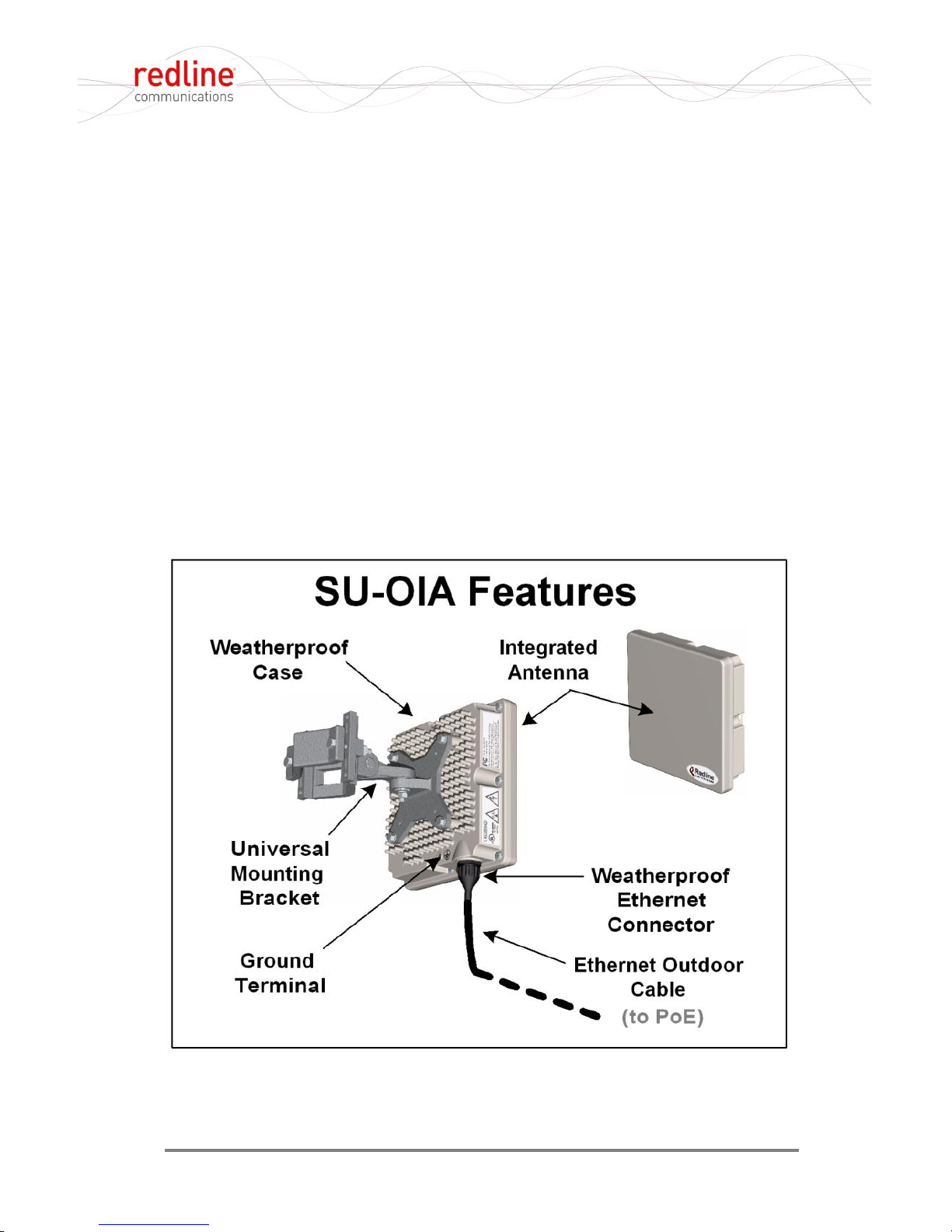
Models SU-OIA and SU-ORF Outdoor Modems (SU-O):
- Outdoor unit must not be installed near power lines or other
electrical power circuits.
- Outdoor units must be properly grounded to protect against power
surges and accumulated static electricity.
- It is the user's responsibility to install this device in accordance
with the local electrical codes: grounding of the transceiver unit,
mast, lead-in wire and discharge unit, location of discharge unit,
size of grounding conductors and connection requirements for
grounding electrodes.
- Do not place the indoor PoE equipment on or near a direct heat
source or operate near water or wet location.
- Do not exceed the limits described on product labels.
- Position power cords to avoid damage; do not overload wall
outlets and use only properly grounded power receptacles.
- Disconnect power before cleaning and use only a damp cloth for
cleaning. Do not use liquid or aerosol cleaners.
- Disconnect power when product is not in use.
- Refer to the Subscriber User Manual (70-00057-01) for additional
safety notices and regulatory information.
4Gon www.4Gon.co.uk [email protected] Tel: +44 (0)1245 808295 Fax: +44 (0)1245 808299

SU-O Quick Install Guide
70-00067-01-02 Proprietary Redline Comm. © 2010 Page 4 of 12 October 9, 2008
2
2
I
In
nt
tr
ro
od
du
uc
ct
ti
io
on
n
The SU-O is a fully integrated WiMAX Forum Certified™ subscriber
unit incorporating an Ethernet interface and wireless interface to a
WiMAX base station. The subscriber is available with integrated
antenna or a selection of external antennas. Mounting options are
available to accommodate pole and wall mount.
3
3
I
In
ns
st
ta
al
ll
la
at
ti
io
on
n
P
Pr
ro
oc
ce
ed
du
ur
re
e
Use the steps outlined in the following sections to assemble and
commission the SU-O:
1. Unpack all SU-O components.
2. Install the SU-O equipment, orienting the SU-O (or external
antenna) in a vertical or horizontal orientation as required.
3. Connect the SU-O to the PoE adapter.
4. Connect the local network device (PC, router, etc) to the PoE.
5. Power-on to configure the SU-O and adjust the antenna as
required.
,
Figure 1: SU-OIA System Features
4Gon www.4Gon.co.uk [email protected] Tel: +44 (0)1245 808295 Fax: +44 (0)1245 808299

SU-O Quick Install Guide
70-00067-01-02 Proprietary Redline Comm. © 2010 Page 5 of 12 October 9, 2008
3.1 Unpack SU-O Components
The following components are supplied with each SU-O:
- SU-OIA equipped with integrated antenna, or SU-ORF equipped
with antenna, antenna bracket, and RF cable.
- Outdoor Ethernet cable
- Auto-sensing 110-240 VAC PoE adapter (indoor use only)
- Lightning protection equipment (optional)
<
Figure 2: SU-ORF System Features
3.2 Install the SU-O
Mounting procedures are dependent on the type of SU-O (integrated
or external antenna). For detailed information, refer to the Subscriber
Installation Guidelines (70-00068-01) on the documentation CD-ROM
supplied with the base station.
3.3 Connect Outdoor Cable to SU-O
The outdoor end of the Ethernet cable supplied by Redline is
terminated with a weatherproof RJ-45 connector. This connector
mates directly to the RJ-45 port located on the SU-O enclosure.
4Gon www.4Gon.co.uk [email protected] Tel: +44 (0)1245 808295 Fax: +44 (0)1245 808299

SU-O Quick Install Guide
70-00067-01-02 Proprietary Redline Comm. © 2010 Page 6 of 12 October 9, 2008
Important Notice: Outdoor Cable Assembly
Redline does not endorse or support the use of outdoor cable assemblies: i) not
supplied by Redline, ii) third-party products that do not meet Redline's cable and
connector assembly specifications, or iii) cables not installed and
weatherproofed as specified in this manual. Refer to the Redline Limited
Standard Warranty and RedCare service agreements.
Figure 3: Outdoor Ethernet Cable - SU-O Cable Connection
The weatherproof connector must be finger-tight plus 1/16th turn
only. Choose a tool suitable to avoid damaging the plastic connector.
The minimum diameter to pass the outdoor connector through a
conduit or hole is 26 mm (1 in).
3.4 Connect the SU-O to the PoE Adapter
The indoor end of this cable is terminated with a standard indoor RJ-
45 connector for connection to the indoor PoE adapter. The SU-O
Ethernet cable must be connected to the PoE port marked 'DATA
AND POWER OUT'.
Figure 4: SU-O PoE Connection: DATA & POWER OUT
The minimum diameter to pass the indoor connector through a
conduit or hole is 18 mm (11/16 in).
4Gon www.4Gon.co.uk [email protected] Tel: +44 (0)1245 808295 Fax: +44 (0)1245 808299

SU-O Quick Install Guide
70-00067-01-02 Proprietary Redline Comm. © 2010 Page 7 of 12 October 9, 2008
Note: Refer to the RedMAX Wireless Access Subscriber Modem
Installation Guidelines (70-00068-01) for information about optional
lightning protection.
3.5 Connect Local Network Device
Connect a CAT-5E Ethernet cable RJ-45 connector to the 'DATA IN'
port on the PoE adapter. The Ethernet cable connects the SU-O to
the local network device. This can be a laptop PC, router, or other
supported network device.
Figure 5: SU-O Power and Network Connections
PoE Power Adapter Caution -- Warning to Service
Personnel: 48 VDC
Connecting customer premises Ethernet equipment directly to
the 'Data and Power Out' connector on the SU-O Power-over-
Ethernet power adapter may damage customer network interface
equipment. Customer equipment including personal computers,
routers, etc., must only be connected to the 'Data In' port on the
PoE unit. Only the outdoors Ethernet interface cable to the SU-O
can be safely connected to the 'Data and Power Out' connector.
4Gon www.4Gon.co.uk [email protected] Tel: +44 (0)1245 808295 Fax: +44 (0)1245 808299

SU-O Quick Install Guide
70-00067-01-02 Proprietary Redline Comm. © 2010 Page 8 of 12 October 9, 2008
3.6 Power-On the SU-O
Connect the PoE power adapter to a 110-240 VAC (nominal)
grounded receptacle. The SU-O is not equipped with a power switch
and activates immediately when connected to a power source. Power
is supplied to the SU-O through the outdoor Ethernet cable.
3.7 Configure SU-O and Align Antenna
Correct antenna alignment is essential in obtaining maximum
performance on the wireless link. A misaligned antenna will decrease
the received signal and you may be unable to connect to any base
station.
The SU-O must be mounted and connected to the Ethernet PoE
adapter before the antenna alignment can be completed. The
alignment must be performed in both the azimuth and elevation
planes. When possible, obtain accurate antenna pointing azimuth
and elevation angles for each installation site.
Base Station Location
For each SU-O installation, the base station antenna will be located
on a tower or building in the area.
Figure 6: Non-Line of Sight Signal from Base Station
The SU-O will receive the best signal when deployed with a visual
line-of-sight (LOS) to the base station. When LOS is not possible
4Gon www.4Gon.co.uk [email protected] Tel: +44 (0)1245 808295 Fax: +44 (0)1245 808299

SU-O Quick Install Guide
70-00067-01-02 Proprietary Redline Comm. © 2010 Page 9 of 12 October 9, 2008
from the SU-O location, the antenna may be aligned to receive base
station signals reflected from nearby buildings or other flat structures.
Azimuth Alignment
The azimuth is aligned by loosening the bolts on the pipe bracket and
rotating the antenna around the pole. If the unit is mounted to flat
surface, there is a single bolt for horizontal adjustment.
Elevation Alignment
The elevation is adjusted by loosening the vertical alignment bolts of
the mounting bracket. Most links will have an elevation of 0º and the
antenna can be adjusted using a bubble (spirit) level.
Adjusting Using Audible Tone
Following basic alignment, small adjustments should be made using
the SU-O audible alignment buzzer. The audible alignment buzzer is
disabled by default. You need a PC with an Ethernet port and a
cross-over type Ethernet cable.
1. Connect a PC to the DATA IN port of the PoE power injector.
2. Start a telnet session, and login to the SU-O. The factory default login
parameters are:
IP Address: 192.168.101.1
Username: admin
Password: admin
3. Enter the (case-sensitive) command to enable the audible signal:
set boardConfig Buzzer 1
The SU-O should now be emitting an audible signal that varies with
the received signal strength. A faster repetition rate of the buzzer
indicates a stronger signal being received from the remote-end
transmitter. Adjust the SU-O antenna by small changes first the
elevation and then the azimuth adjustments to obtain a maximum
reading.
The audible alignment signal remains active until disabled by the
operator. Enter the following command to disable the audible signal:
set boardConfig Buzzer 0
Enable the SU-O Monitor Mode
RSSI information is also available using Telnet. Enter the following
command to enable the monitor display:
monitor <ENTER>
The display is updated continuously with the latest statistics values.
Hit any key to exit from the monitor display.
4Gon www.4Gon.co.uk [email protected] Tel: +44 (0)1245 808295 Fax: +44 (0)1245 808299

SU-O Quick Install Guide
70-00067-01-02 Proprietary Redline Comm. © 2010 Page 10 of 12 October 9, 2008
Adjusting the Antenna
It is recommended to align the antenna to obtain the maximum SNR
value. The SNR (Signal/Noise Ratio) is a measure of the signal
quality, while RfRssi (Radio Frequency Received Signal Strength
Indicator) is a measure of the signal strength. Usually a higher SNR
will be coincident with a stronger signal, however, this may not be the
case when interference is present.
The SNR and RfRssi readings are available on the Telnet interface of
the subscriber station. Use the 'monitor' mode to provide a
dynamically updated display of the RSSI and other subscriber
statistics. From the root CLI mode, enter the following command to
activate the monitor display:
monitor <ENTER>
When monitor mode is active, the screen is updated continuously
with the latest subscriber statistics values. Hit any key to exit from
monitor mode.
Figure 7: Monitor Mode Screen
Note: RfRssi values are negative, and an RfRssi of -35 dBm is
stronger than -50 dBm.
4Gon www.4Gon.co.uk [email protected] Tel: +44 (0)1245 808295 Fax: +44 (0)1245 808299

SU-O Quick Install Guide
70-00067-01-02 Proprietary Redline Comm. © 2010 Page 11 of 12 October 9, 2008
Adjust the subscriber antenna by first adjusting the antenna through
complete sweeps of the elevation and then the azimuth. During these
sweeps, the SNR value should increase when aligned to a sidelobe,
decrease as the antenna is moved further, and then increase to a
higher value when the antenna is aligned to the most direct signal
path. Additional movement of the antenna will cause the SNR value
to decrease and then fluctuate as it aligns to another sidelobe.
Aligning the antenna to a sidelobe may result in low or unstable
readings. In some cases where interference is present, the optimum
alignment position based on highest SNR may not provide the
highest achieved RfRssi reading.
Once the alignment sweep has been completed, the RfRssi value
should be checked against the estimated value obtained from the link
budget. For a LOS link the measured RfRssi should be within five
dBm of the calculated value. A lower reading may indicate that the
antenna is aligned to a sidelobe. If the RfRssi is much lower than the
calculated value, this may indicate an optical LOS or non LOS path --
re. If the link is non LOS a suitable reflecting surface such as a
building or billboard must be used. For non LOS deployments, it is
necessary to install the link and perform vertical and horizontal
sweeps of the antenna to determine if the required throughput can be
achieved.
When the alignment is complete, partially tighten all bolts. Tighten
each bolt in a cross-pattern to minimize shifts in the antenna
alignment. Tighten all bolts securely.
4Gon www.4Gon.co.uk [email protected] Tel: +44 (0)1245 808295 Fax: +44 (0)1245 808299

70-00067-01-02 Proprietary Redline Comm. © 2010 Page 12 of 12 October 9, 2008
4Gon www.4Gon.co.uk [email protected] Tel: +44 (0)1245 808295 Fax: +44 (0)1245 808299
Table of contents
Popular Gateway manuals by other brands

enphase
enphase CT-100-SPLIT ROW Installation instruction

ADTRAN
ADTRAN SMART/RG SR506n user manual

Cooper
Cooper ProtoNode FPC-N34 Startup guide

Cermate Technologies
Cermate Technologies S-BOX installation guide

infinias
infinias S-IMS-A Intelli-M Installation and user guide

nilan
nilan Compact S installation instructions