Redline GM POWER SMOKE RLD950103GM User manual

OPERATION MANUAL P/N RLD950103GM
DIAGNOSTIC LEAK DETECTOR
GM ™

CONTENTS
Specifications .................................................................................................................................................. 1
Reference Guide ............................................................................................................................................. 2
Safety ................................................................................................................................................................. 3
Accessories ..................................................................................................................................................... 4
GM Power Smoke™ Set up ........................................................................................................................... 5
Adaptor Installation ........................................................................................................................................ 6
Testing for Leaks ........................................................................................................................................ 7 - 8
Trouble Shooting ............................................................................................................................................. 8
Warranty .......................................................................................................................................................... 9
Replacement Parts ........................................................................................................................................... 9
Technical Support: 1-866-55-SMOKE
+1 714-451-1411
GM Technical Support: 1-800-GM-TOOLS
You will receive a call or email response
within six (6) hours
Shop Online: www.RedlineDetection.com

1
SPECIFICATIONS
Dimensions 9 in. x 9 in. x 15 in. (23 cm x 23 cm x 38 cm)
Weight - GM Power Smoke™ 19 lbs. (9 kg)
Weight - Accessory Kit Only 16 lbs. (8 kg)
Weight - Shipping 41 lbs. (18.5 kg)
Power Supply 110-240V AC or 12V DC
Pressure Supply Compressed Air
Output Pressure 2 to 20+ PSI (0.14 to 1.4+ BAR)
Operating Temperature 0°F to 140°F (-17°C to 60°C)
Operating Humidity No Restrictions
Operating Altitude No Restrictions
Smoke Output Hose 15 ft. (5 m)
12V Power Cable 15 ft. (5 m)
Operating Modes Smoke Cycle / Air Only Cycle
Housing Material Steel
Smoke Chamber Material Billet Aluminum
Smoke Chamber Assembly Bolted
Smoke Chamber Warranty Lifetime
GM Power Smoke™ Warranty 1 Year

2
REFERENCE GUIDE
FRONT VIEW
BACK VIEW
2
1
9
8
3
4
5 6 7
10
14
15
12
13
11
16
1. Flow Control Knob (Variable)
Releases vapoR / pRessuRe into the system
Close flow ContRol valve to loCk out system foR
pRessuRe deCay testing
2. SyStem PreSSure GauGe
displays the baCk pRessuRe of system undeR test
3. Flow meter
measuRes flow Rate into system undeR test
4. Power indiCator
gReen light indiCates pRopeR ConneCtion to eleCtRiCal
poweR
5. VaPor teSt SwitCh
begins ten-minute vapoR CyCle. Red light indiCates
vapoR CyCle. push again to stop testing
6. air only teSt SwitCh
begins ten-minute aiR only CyCle. blue light indiCates
aiR only CyCle. push again to stop testing
7. reSet SwitCh
CleaRs stoRed logiC
8. adjuStable PreSSure reGulator
adjust test pRessuRe fRom 2 to 20+ psi (0.14 to
1.4+ baR)
9. teSt PreSSure GauGe
indiCates test pRessuRe set by RegulatoR
10. Fluid Fill Port
Remove fluid fill plug to fill maChine with oem-
appRoved vapoR pRoduCing fluid
11. ComPreSSed air inlet
ReplaCe CoupleR fitting if neCessaRy. female 1/4 in.
npt fitting
12. VaPor outPut hoSe
13. 12 Volt dC Power CableS
14. international aC Power inlet (110-240V)
15. Power SuPPly SeleCtor SwitCh
aC-off-dC
16. FuSe holder
10a 250v fuse plus one spaRe fuse

3
SAFETY
GM Power Smoke™ is designed to be used in conjunction with the supplied GM Graduated Adaptors,
PowerSmoke™ Adaptors, or threaded sensor port adaptors to test the intake and exhaust systems of
boosted engines.
DO NOT USE IN EVAP SYSTEM
GM Power Smoke™ utilizes higher test pressure that may damage components in evaporative emission
systems. Redline Detection manufactures OEM approved EVAP leak detectors such as, Smoke Pro®
Total-Tech® [ 95-0003/C ] and Smoke Pro Air Complete™ [ 95-0051 ] which are specifically designed for
EVAP system and general repair diagnostics.
SAFETY TIPS
• All diagnostic work should be performed with the engine off
• For use only by professional technicians
• Ensure that the vehicle is secure and stable
• Exercise caution when connecting and disconnecting compressed shop air supply
• Do not leave a vehicle unattended while equipment is operating
• Always wear proper safety protection
• This safety guide is not intended to take the place of common sense and good judgment
PowerSmoke™ Adaptor Safety
:
• The maximum test pressure a PowerSmoke™ Adaptor may restrain can only be estimated.
• Slippage of a PowerSmoke™ Adaptor is influenced by many factors including debris / residue in the
Intake / Exhaust system, coefficient of friction, internal pressure of the PowerSmoke™ Adaptor, and the
accuracy of inflation instruments.
• Generally, a PowerSmoke™ Adaptor properly inserted into an Intake / Exhaust system may begin
slipping when test pressure exceeds 50% of the internal inflation pressure. Inflation pressure and back
pressure limitations are subject to temperature / humidity change.
• PowerSmoke™ Adaptor should NEVER be inflated over 1.6 times its deflated outside diameter.
• Debris, protrusions and residue in the Intake/Exhaust system could weaken and / or rupture the bladder
of the PowerSmoke™ Adaptor. Bladder failures due to misuse or abuse are not covered by warranty.
Redline Detection shall not be responsible for any incidental or consequential damages.
• PowerSmoke™ Adaptor must be mechanically anchored with the provided chain/cable to a secure
anchor before use.
• PowerSmoke™ Adaptor slippage under test pressures may cause property damage or injury.
• NEVER use inflation pressure with PowerSmoke™ Adaptor or a test pressure that is greater than the
capacity of the weakest component in the system under test.
• NEVER use Powersmoke™ Adaptor when its failure could cause injury or catastrophic damage.
• Before use: Refer to PowerSmoke™ Adaptor Installation & Inflation procedures, back pressure
limitations and tether restraint installation instructions.
!

64
1. Accessory Storage Case [ RLD910006 ]
Store all included accessories.
2. GM Graduated Adaptor (4 tier) [ RLD960202]
Quad diameter adaptor to test induction system.
3. GM Graduated Adaptor (5 tier) [ RLD960203]
Triple diameter adaptor to test induction system.
4. PowerSmoke™ Adaptor 2.9 in. (7.4 cm) Diameter [ RLD950081/B ]
Inflatable block off bladder with a pressurized vapor
pass-through
5. PowerSmoke™ Adaptor 1.9 in. (4.8 cm) Diameter [ RLD950086 ]
Inflatable block off bladder with a pressurized vapor
pass-through
6. Block Off Coupler [ RLD960084 ]
Caps off vapor pass through to convert above adaptors to
block off adaptors
7. Halogen Inspection Light [ RLD960011 ]
12V DC with 20 ft. (6.1 m) cable. Always use to pinpoint leaks
8. AC Power Cable [ RLD200010 ]
Use when selecting AC Power. Make sure cable is rated to
match input voltage and plug configuration
9. GM-Approved Smoke Producing Fluid 8 fl. oz. (237 ml)
[ RLD960039GM ]
Smoke Producing Fluid will perform over 500+ typical tests per
bottle Important: Contains NO Dye / Contaminants
10. Hex Key [ RLD800009 ]
To remove / replace fluid fill port plug
11. Oxygen Sensor Port Adaptor [ RLD150059 ]
Use to access exhaust system through oxygen sensor port
12. Temperature Sensor Port Adaptor [ RLD150056 ]
Use to access intake or exhaust system through
temperature-sensor port
13. Pressure Sensor Port Adaptor [ RLD150055 ]
Use to access intake or exhaust system through pressure
sensor port
14. Cooling System Adaptor [ RLD960086 ]
15. SmokeMeister™ Wand Adaptor [ RLD960088 ]
Tube delivers vapor to find wind and water leaks in cabin or
trunk
16. Power Intake™ Adaptor 1.5 in. (4.8 cm) [ RLD950080 ]
Inflatable block-off bladder with vapor pass-through
4
3
2
5
6
8
7
9
10
11
12
1
13
14
15
16
ACCESSORIES
QUANTITY
1
1
1
1
1
2
1
1
2
1
1
1
1
1
1
1

75
SET UP
1. FILL / ADD APPROVED VAPOR PRODUCING FLUID
a. Remove vapor producing fluid fill plug with hex key
b. Pour GM-Approved Vapor Producing Fluid into vapor producing fluid fill port
Note: Use only GM-Approved Vapor Producing Fluid part number : RLD960036
c. Fill vapor fluid fill port until fluid level is near top of port
2 fl. oz. (60 ml) maximum to refill when empty
d. Replace vapor producing fluid fill plug
Never use dye / UV dye in GM intake or exhaust systems because it
may coat or harm critical sensors
2. CONNECT TO ELECTRICAL POWER SOURCE
• Use the power selector switch on rear of machine to select input power,
AC or DC
• If 12 Volt DC is preferred, connect the battery cables to a fully charged
12 Volt battery. RED to positive, BLACK to chassis ground
• If AC power is preferred, connect a properly rated power cord into the
AC Power Port
a. GREEN LIGHT indicates power is ON
DO NOT connect GM POWERSMOKE™Diagnostic
Leak Detector to a battery charger or jumper box
NEVER connect GM POWERSMOKE™Diagnostic
Leak Detector to a vehicle with engine running
3. CONNECT TO PRESSURIZED AIR SUPPLY
a. Connect compressed air supply to Air Inlet
*Replace quick coupler fitting if necessary. 1/4 in. NPT male
4. ADJUST GM POWERSMOKE™DIAGNOSTIC LEAK DETECTOR FOR TESTING
a. Close flow control valve
b. Pull pressure regulator knob to unlock
c. Push Vapor or Air Only Test to begin 10 minute cycle. Push again to stop
RED LIGHT indicates Vapor Test
BLUE LIGHT indicates Air Only Test
d. Turn pressure regulator knob to desired test pressure. To adjust,
turn clockwise to increase, counter clockwise to decrease.
e. Push pressure regulator knob to lock.
!
!
!
!
5. OPEN FLOW CONTROL VALVE TO RELEASE VAPOR / PRESSURE
6. USE INSPECTION LIGHT TO LOCATE LEAKS
7. PERFORM REPAIR
8. REPEAT TEST TO CONFIRM REPAIRS

6
PowerSmoke™ADAPTOR
INSTALLATION
Safety Warnings:
• The maximum test pressure a PowerSmoke™ Adaptor may restrain can only be estimated
• Slippage of a PowerSmoke™ Adaptor is influenced by many factors including debris / residue in the Intake / Exhaust system,
coefficient of friction, internal pressure of the PowerSmoke™ Adaptor, and the accuracy of inflation instruments
• Generally, a PowerSmoke™ Adaptor properly inserted into an Intake / Exhaust system may begin slipping when test pressure exceeds
50% of the internal inflation pressure. Inflation pressure and back pressure limitations are subject to temperature / humidity change
• PowerSmoke™ Adaptor should NEVER be inflated over 1.6 times its outside diameter
• Debris, protrusions and residue in the Intake / Exhaust system could weaken and / or rupture the bladder of the PowerSmoke™
Adaptor. Bladder failures due to misuse or abuse are not covered by warranty. Redline Detection shall not be responsible for any
incidental or consequential damages
• PowerSmoke™ Adaptor must be mechanically anchored with the provided chain / cable to a secure location before use.
• PowerSmoke™ Adaptor slippage under test pressures may cause property damage or injury
• NEVER use inflation pressure with PowerSmoke™ Adaptor or a test pressure that is greater than the capacity of the weakest
component in the system under test
• NEVER use PowerSmoke™ Adaptor when its failure could cause injury or catastrophic damage
• Before use: Refer to PowerSmoke™ Adaptor Installation and Inflation procedures, back pressure limitations and tether restraint
installation instructions
1. Install PowerSmoke™ Adaptor fully into intake system ductwork or exhaust tubing. Make sure there are no obstructions or sharp
edges that might puncture bladder when inflated. PowerSmoke™ Adaptor must insert completely inside ducting / tubing
2. Install safety chain / cable to a secure location
3. Inflate PowerSmoke™ Adaptor to 30 PSI (2 BAR) maximum. If over inflated, pop off safety valve may release. If release occurs,
reinflate to 30 PSI (2 BAR)
4. Firmly tug on safety chain to insure PowerSmoke™ Adaptor is firmly installed and properly secure
5. Attach vapor hose for testing
Removal of PowerSmoke™ Adaptor:
1. Remove vapor hose (or block-off coupler) at quick coupler to deflate tested system
2. ONLY AFTER system under test is fully depressurized, release internal pressure of PowerSmoke™
slowly by depressing Schrader valve
3. Detach safety chain / cable
4. Remove PowerSmoke™ Adaptor from ductwork, making sure not to rub across sharp edges
Read all safety instructions in the Safety Information section of the Engine Service Manual or
Engine Diagnostic Manual. Failure to comply may result in personal injury and / or death.
SAFETY TIPS
• All diagnostic work should be performed with the engine off
• Do NOT use in EVAP system
• Ensure that the vehicle is secure and stable
• Exercise caution when connecting and disconnecting compressed shop air supply
• Do NOT leave a vehicle unattended while equipment is operating
• Always wear proper safety protection
• This safety guide is not intended to take the place of common sense and good judgment
Proper Installation Improper Installation

7
TESTING FOR LEAKS
Intake System Leak Testing
This test will find any leaks in ducting, charged air cooler, turbocharger, intake manifold,
throttle body, seals, gaskets, hoses, etc.
Seal off intake system by installing GM Graduated Adaptor or PowerSmoke™ Adaptor (see instructions)
into intake ducting after air cleaner box. Begin a 10-minute smoke cycle and pressurize entire system with
smoke at 5 PSI (0.35 BAR) while inspecting for leaks using provided Halogen inspection light. If no leaks
are present, increase pressure to 10 PSI (0.7 BAR) to observe leaks. Retest after repairs are performed to
confirm proper repair and seal.
Exhaust System LeakTesting
This test will find any leaks in exhaust tubing, clamps, flex pipe, muffler, diesel particulate
filter, turbocharger, exhaust manifold, etc.
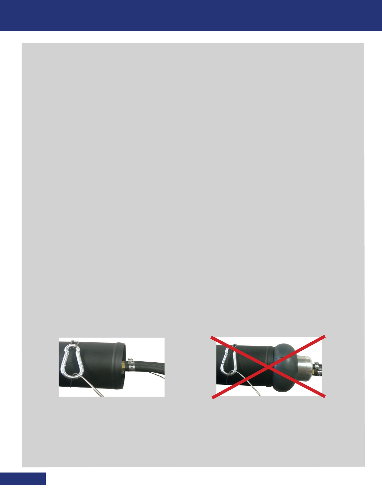
Seal off exhaust system by installing PowerSmoke™ Adaptor (see instructions) into exhaust pipe. If using
inside exhaust stack use the exhaust retention hoop to keep PowerSmoke™ Adaptor from falling inside
exhaust stack. Exhaust Particulate Filter or Catalytic Convertor may not allow visible vapor to pass through
because the particulates get trapped. In that case you may use block off coupler to convert PowerSmoke™
Adaptor into a block off adaptor while injecting smoke into the system using the Temperature Sensor Port
Adaptor, Pressure Sensor Port Adaptor or Oxygen Sensor Port Adaptor. These adaptors give you a great
amount of flexibility in testing all areas of the exhaust system. Retest after repairs are performed to confirm
proper repair and seal.
Combination Intake / ExhaustTesting
Some vehicles allow for a single procedure to test the entire intake and exhaust system at
one time.
Many engine systems can be tested from the air box to the tip of the exhaust completely in a single test. To
do so, install PowerSmoke™ Adaptor (see instructions) into intake ducting after air cleaner box AND install
PowerSmoke™ Adaptor (see instructions) into exhaust pipe. Convert PowerSmoke™ Adaptor in exhaust
system into a block off by installing block off coupler. Inject smoke into the intake system through the
PowerSmoke™ Adaptor. Pressurize entire system inspecting for leaks. Note: Complete system testing can
will occur when valve overlap is present or EGR valve is in open position. In cases where valve overlap
cannot occur or EGR may not be opened either manually or computer controlled, separate system testing
must be performed. Retest after repairs are performed to confirm proper repair and seal.
Cabin Leak Testing
Test for driver cabin exhaust / carbon monoxide infiltration, wind & water leaks.
Key on / Engine off, turn circulation fan to its highest speed making sure that the fresh air option is used
(NOT recirculate). If vehicle has dual air option, also initiate fan, selecting highest fan speed setting. The
circulation fan produces a positive cabin pressure. Make sure all windows and doors are completely
closed. Install SmokeMeister Wand (optional) to end of Smoke hose. Set test pressure to 3 PSI (0.2 BAR).
Make sure test is performed in a “still air” environment such as in a closed building. Using SmokeMeister
Wand (optional) proceed around vehicle cabin laying down fluffy smoke on all seams, seals and joints
looking for smoke vapor deflection from escaping air (leaks). Where smoke vapor is deflected is a visual
conformation of a leak. Seal leak and retest entire cabin for further leaks. To check for doghouse engine
cover leaks, turn off fans, install wand tip adaptor into wand, and inject smoke underside of doghouse
while someone inside cabin looks for leaks. Retest after repairs are performed to confirm proper repair
and seal.

8
PROBLEM SOLUTION
No Green Light • Check for proper battery voltage
• Align power supply switch with input (AC or DC)
• Check polarity if 12V DC is selected
• Check fuse if AC Power is selected
Red Light Flashing • Open circuit / internal component
• Contact Redline Technical Support
866-55-SMOKE or +1 714-451-1411
No Air Flow • Check connection to compressed air
• Open the flow control valve
• Check hoses are not kinked or pushed into machine
Poor Smoke Density or Volume • Insufficient Smoke Producing Fluid: Refill
• Flow Control Valve is partially closed
• Smoke Output Hose is kinked
High Test Pressure Reading • Smoke Output Hose is kinked
Coolant System LeakTesting
Cooling system leak testing can be performed two ways
Use GM Power Smoke™ to quickly and easily find cooling system leaks either with decay testing or using
visible vapor. First, attach (optional) cooling system adaptor to pressurized coolant bottle or radiator at
cap. For decay testing, simply pressurize coolant system with air-only to manufacturers recommended
test pressure, typically 15 PSI (1 BAR). Turn off flow control valve to lock out system and watch for
decay. Inspect visually for leaking fluid. Alternatively, to perform leak test using smoke vapor, first drain
the cooling system of all fluid. Introduce pressurized vapor in to cooling system at no more than the
manufacturers recommended test pressure and use inspection light to find leaks. Retest after repairs are
performed to confirm proper repair and seal.
IMPORTANT NOTE
Many leaks in systems are considered “normal” or “within tolerance.” For example,
a weep hole in a muffler is acceptable. DO NOT assume every wisp of smoke represents a
failing component. Check with vehicle manufacturer before replacing suspected failed part.
!
TROUBLESHOOTING
TESTING FOR LEAKS CONTINUED

9
WARRANTY
The manufacturer, Redline Detection, LLC (“Redline”) warrants this product to be free from defects in workmanship and material
under normal use and service for a period of one-year from the date of purchase. Redline’s liability under this warranty is limited
to: (1) repair or replacement of any parts or product which are determined to be defective; or at Redline’s sole option (2) refund
of the purchase price. In either event, product to be returned shipping prepaid within the one year warranty period. Additionally,
the smoke chamber in any Redline product has a lifetime warranty as to its structural integrity: Any Redline-manufactured
smoke chamber that leaks, cracks, or separates in any way shall be repaired or replaced by Redline at no charge. Products are
only to be used by persons having skill and knowledge in the motor vehicle repair field, and improper use or maintenance may
cause serious injury. In no event shall Redline be liable beyond replacement of product or refund of the purchase price. This
warranty shall void if a product is improperly maintained, altered, abused or otherwise misused in any way.
THE AFORESAID WARRANTY IS IN LIEU OF ALL OTHER WARRANTIES, AND THERE ARE NO OTHER WARRANTIES OR
REPRESENTATIONS OF ANY KIND WHATSOEVER MADE BY REDLINE, EITHER EXPRESSED OR IMPLIED, INCLUDING BUT NOT
LIMITED TO, ANY IMPLIED WARRANTY OF MERCHANTABILITY OR FITNESS FOR A PARTICULAR USE OR APPLICATION.
THE PURCHASER’S SOLE REMEDY FOR ANY DEFECTIVE PRODUCT SHALL BE REPAIR, REPLACEMENT OR REFUND AS STATED
ABOVE AND REDLINE SHALL NOT BE LIABLE TO ANYONE FOR ANY SPECIAL, CONSEQUENTIAL, INCIDENTAL, INDIRECT OR
PUNITIVE DAMAGES ON ACCOUNT OF DEFECTIVE PRODUCTS, HOWEVER CAUSED, UNDER ANY THEORY OF LABILITY.
REPLACEMENT PARTS
ADDITIONAL ACCESSORIES
For replacement parts, please call:
GM Technical Support: 1-800-GM-TOOLS
1. GM Smoke Producing Fluid [ RLD960036 ]
2. Flowmeter [ RLD300023 ]
3. System Pressure Gauge [ RLD300020 ]
4. Test Pressure Gauge [ RLD300018 ]
5. Replacement Bladder 1.9 in. (4.8 cm) [RLD100031 ]
6. Replacement Bladder 2.9 in. (7.4 cm) [ RLD100035]
7. Replacement Halogen Bulb [ RLD200002 ]
1. PowerSmoke™Adaptor 3.9 in. (10 cm) [RLD950080 ]
2. Wand / Tip Adapter [ RLD150080 ]
1234
6 75
1
2

Manufactured By
Redline Detection, LLC
Technical Support +1 714-451-1411
Shop Online: www.RedlineDetection.com
*
* with global components
Table of contents
Other Redline Security Sensor manuals
Popular Security Sensor manuals by other brands

C.P. Electronics
C.P. Electronics EBDHS-DNET1 installation guide

Maxouttech
Maxouttech RF-ARPIR-319-NN installation instructions

Heath Zenith
Heath Zenith SECUR360 9304 manual

GSM Activate
GSM Activate IR BEAM manual

Sensor Switch
Sensor Switch WSX instructions

Abus
Abus Alarmbox RC Brief instructions for installation and initial commissioning