REDROTOR RC STRIDER 250 User manual

STRIDER 250 V1.1
REDROTOR RC

Table of contents

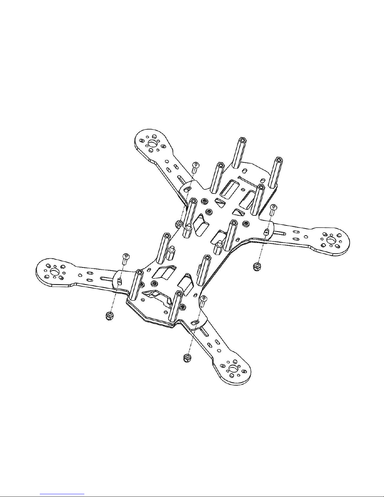
Center Plate with onboard RROSD engine (x1)
Bottom Plate (x1)
Top Plate (x1)
Arms (x4)
HD Plate (x1)
CCD Board Camera mount (x1)
Aluminum M3 x 6mm (x10) (top plate)
Aluminum M3 x 8mm (x4) (arm pivot)
Aluminum M3 x 10mm (x4) (arm slot)
Aluminum M3 x 16mm (x10) (lower plates)
Nylon M3 x 3mm Spacer (x14) (lower plates)
Nylon M3 x 12mm (x4) (flight controller)
Nylon M3 hex nut (x4) (flight controller)
Nylon 35mm F/F Standoff (x10) (center frame)
Nylon 10mm M/F Standoff (x4) (flight controller)
Nylon M3 washer (x4) (arm pivot)
Rubber Soft Bobbin (x3) (HD plate)
Captive nut (x8) (RROSD plate)
M3 Nylon locking nut (x4) (arm slot)
*Don’t be alarm if you see extra hardware, those are included as spares
If you find anything missing please contact your retailer or email SUPPORT@REDROTOR.COM immediately.
M3 Allen/hex key/driver *size #2
M3 Hex socket driver
Soldering Iron with a thick tip
60/40 Rosin core solder or varying thickness
Shrink Tubing of various diameters
(Optional but recommended) Zip ties of varying sizes
(Optional but recommended) Battery Strap (Scorpion or other branded Straps)
(Optional but recommended) Wire Mesh Braid or Paracord

! - 4S+1.3Ghz warning –VTX and Camera are both filtered. Only camera power is regulated at (12V or 5V).
Power to the VTX pins is not regulated! The flight battery voltage will be applied. Most 5.8 Ghz video
transmitters have a built in regulator with a wide range to easily accept 3S –4S standard. Most 1.3 Ghz
video transmitters do not have built in regulators and will need a 12V mini regulator in place on the video
out pins if using a 4S flight pack. A product like this can be wired in before the VTX power connections
! –Power/Ground wire soldering –Caution must be taken when soldering wires to the power and ground
pads on the PDB. There are many sensitive components on the RROSD board that a hot soldering iron can
ruin or de-solder if carelessly placed

Below is a list of recommended gear to get you airborne.
Flight Controller (x1)
oCC3D
oNaze32
oFlip
10A minimum speed controllers (x4)
oHobby King Blue Series 12A
oBheli Red Series 12A
oKISS ESC 12A/18A
Mini multi-rotor (x4)
oDYS 1806 2300kv
oCobra 2204 1960kv (4S recommended)
oCobra 2204 2300kv
oSunnysky x2204 2300kv
oTurnigy Multi-star 2204 2300kv
18-14 AWG cable (preferably silicon coated) (10”)
Battery connector (Deans, T-plug, XT60, etc. to match your battery style)
3S or 4S LiPo Batteries(1300-2200 mAh)
5”-6” propellers
oGemfan 5030
oGemfan 5040
oHQ Carbon Composite 5045
oHQ Carbon Composite 6030
oHQ Carbon Composite 6045
1 pin Female to Female Standard Servo Cable (x2) or 3 pin F/F
Radio Receiver
oFrsky DR4-ii (2.4Ghz recommended)
oEzUHF (long range)
oSpektrum 2.4Ghz
Radio
oFrsky Taranis
oTurnigy 9XR
oSpektrum

Video Transmitter
(Optional but recommended) SMA Pigtail lead (4” – 6”)
Video Antenna
oImmersion RC Skew planer Set (5.8)
FPV Camera
oHS1177
oPZ0420
oNerdCam (3D)
(Optional but recommended) HD Action Camera
oMobius
oDiminika
oGoPro Hero
oGoPro Clone
Monitor or FPV Goggles
Receiver or FPV Goggles with built in Video Receiver

1. Lay Nylon M3 x 12mm (x4) flat and insert through bottom plate. Top with Nylon M3 x 3mm Spacer (x4)

2. Lay center plate with electronics facing upward on top of bottom plate. Hand tighten Nylon 10mm M/F
Standoff (x4) securely onto screws

3. Slide a nylon spacer in between plates and insert a 16mm Aluminum screw through hole. Hand tighten
35mm Nylon standoff to it. Repeat 10x until all edges are complete

4. Slide Arm in between plates taking note of bolt pattern so your motor wiring faces inward. Insert Aluminum
M3 x 10mm through slot in plates/arm. Tighten M3 Nylon locking nut so that the arm can still move loosely.
Repeat 4x until all arms are attached

5. Flip the Strider over and move arm into position so the notch at the end is aligned with the 5” or 6” hole in
the bottom of the center plate. Put a M3 washer on Aluminum M3 x 8mm and insert as shown from the
bottom of the frame. Screw loosely into captive nut. Push arm inward against screw and angle arm forward
so it sits as far forward as possible in the kidney shaped slot. Tighten Screw fully. Tighten nylon locknut
until arm can only be moved with hard force. Repeat 4x until all 4 arms are assembled.*Shown below in 5”
configuration. For 6” use the outer holes

1. Mount motors to arms, there are both 16mm x 19mm M3 slots and 12mm x 16mm M2 slots. You may have to flip
the arm over if your motor wires are facing the wrong direction
2. Install ESCs (3m heavy duty mounting tape, also there are zip tie slots on the edge of frame)

3. Solder ESCs to RROSD
3.1. Bottom ESC wires routing
3.2. Top ESC wires routing
4. Solder motors to ESCs (install braid optional)

5. Check motor direction and swap a wires if it’s incorrectly spinning
6. Solder battery cable to designated pads between ESC pads (install braid optional)
7. Connection to CAM and VTX (see warning section above if using 4s and 1.3Ghz)
Rev 1.1 does not have solder bridges and accepts 3s or 4s natively. There are dual outputs for 12v and 5v on the
board which can be used for camera or accessories

8. Connection from Receiver to Flight Controller
8.1. shown using Frsky passing CCPM to Naze32
8.2. Shown using FrSky passing CCPM to CC3D

9. 3-position switch & RSSI signal connection to RROSD
10. Mount Flight Controller with Nylon Hex nuts. Connect Motor Signals from ESC to flight controller. (Only one Power
and Ground wire is required) A servo crimper and 2.54mm jumper pins can be used to shorten cabling

The below CLI commands are recommended when using a Naze32 FC and PPM input:
1. feature ppm (necessary when using a PPM compatible receiver such as DR4-ii)
2. feature motor_stop keeps motors from spinning up when armed
3. map taer1234 (channel settings for Throttle/Aileron/Elevator/Rudder)
4. set align_board_yaw = 270 (Board orientation as shown in this build)
5. set gimbal_flags = 4 (make Aux signal available on PWM output channels)
6. set looptime = 2500 (or 2530) Mini quad suggested loop time (ESC signal refresh rate)
The below steps in OpenPilot GCS are required to make Aux signal available on CC3D FC:
1. Make sure to program the 3-position switch to Accessory0 during “Transmitter Setup Wizard”
2. Under “Hardware Settings” in Configuration Tab, set RcvPort to “PPM+Outputs”
3. Under “Output” in Configuration Tab, set output channel 7 middle and max value to 1500 and 2000
respectively

4. In “System” Tab, set Mixer7Type to “Accessory0”
Download the Firmware Upgrade Utility software from http://redrotorrc.com/download/RRLoader-
1.2.zip
Unzip and run the installer (RRLoader.msi)
Connect the USB-to-Serial dongle (RR-PRGM) to a PC running Win XP/7/8 and make note of the installed
COM #
You can also go Device Manager to find out the COM number

Connect the USB dongle to RROSD Expansion port with a 3-pin cable as shown. Make sure the
battery is unplugged from your Strider

Run “RRLoader.exe” (icon created on your desktop)
As a safety caution, remove all props first, and connect power to the Strider
Choose the correct COM number, and click “Load”
Remove power and disconnect programmer from RROSD when firmware loading is finished
Power up Strider and the OSD version listed on initial boot-up on the on screen display should be
updated if everything worked correctly
To switch between video modes hold down on the button on the right edge of the RROSD board. Keep
depressed while power up the board. Keep the button depressed for around 10 seconds until the LEDs turn
on. Release the button and unplug the battery, you have now switched modes
The RROSD LEDS, buzzer, crosshair, timer start/stop, and Lost Model Mode are all controlled via a 3
position switch. The switch should be set to center before plugging in
Each flip of the switch to the high position will:
Start the Timer (if it’s stopped)
Pause the timer (if it’s running)
Deactivate the crosshair
Each flip of the switch back to center will:
Reactivate the crosshair
Each flip of the switch to the low position will:
Cycle through 3 modes: Activate LEDs full on Activate Lost Model Mode (strobe lights and
buzzer) LEDS and buzzer deactivated
To enter into the menu of the RROSD, power up the board and hold down on the button on the right edge
of the RROSD board within 3 seconds of powering up. Keep it depressed until the menu appears in your
view then release
Other manuals for STRIDER 250
1
Other REDROTOR RC Quadcopter manuals