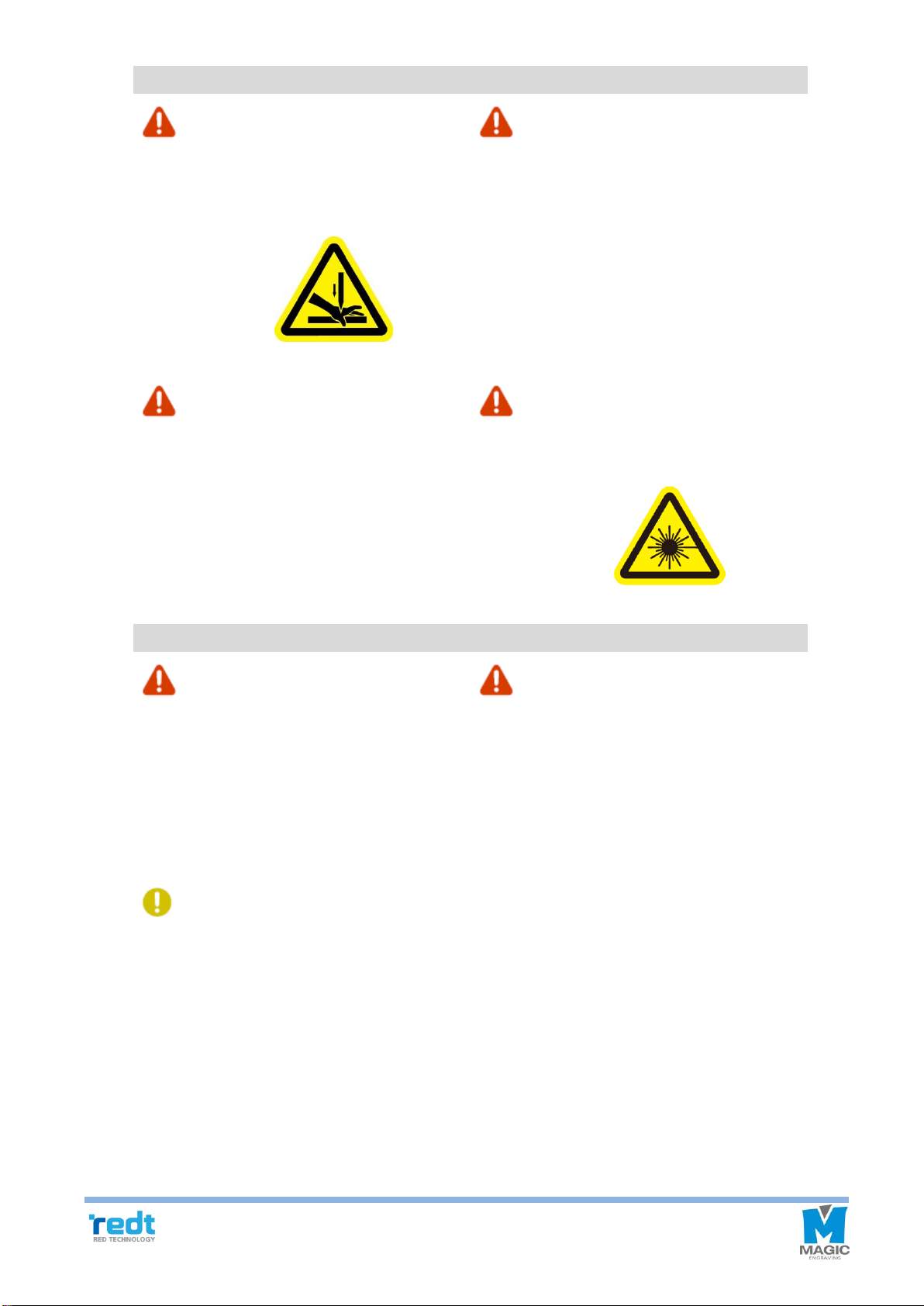
REDT R&D MAGIC-70 User manual

R&D by REDT
http://www.redt-magic-engraver.com
3F, (1314 Gwanpyeong-dong) 13-10, Techno 2-ro, Yuseong-gu,
Daejeon, Republic of Korea, 305-709
TEL: +82-70-7011-0905 FAX: +82-42-673-0905

1
Contents
Cautions for Use 3
Product Parts and Installation 5
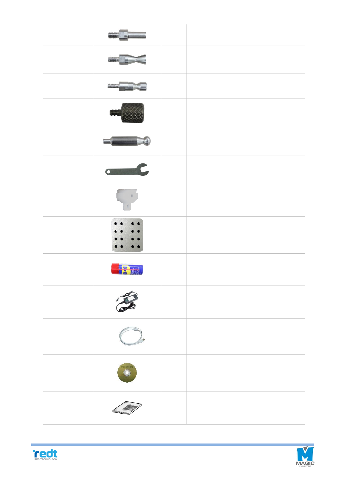
1) Parts and Accessories........................................................................................ 5
2) Specifications ..................................................................................................... 7
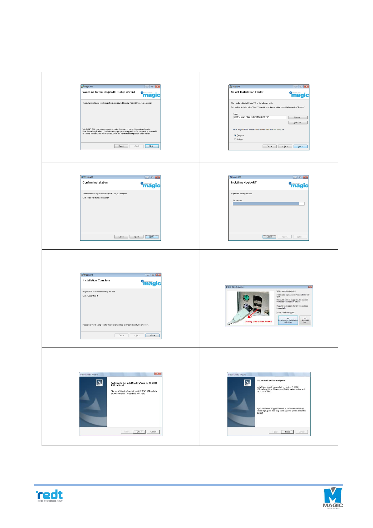
3) MagicArt S/W Program Installation .................................................................... 8
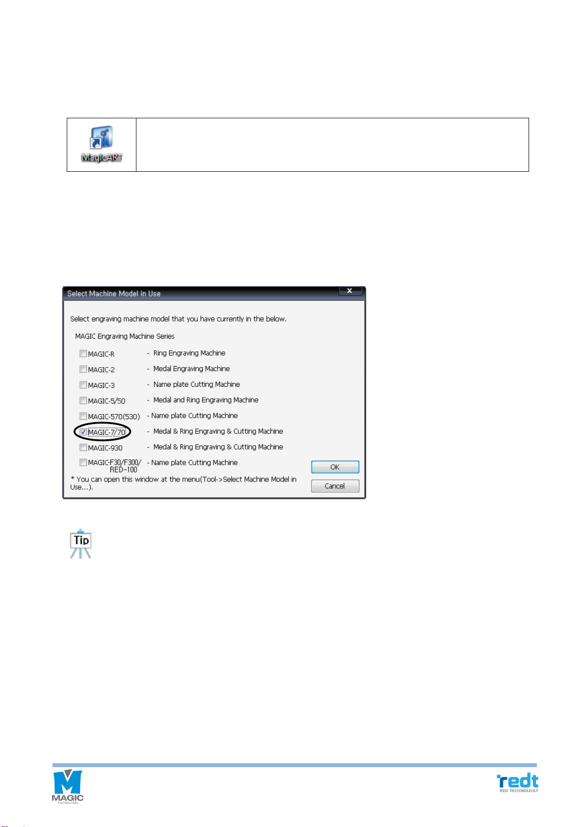
4) MAGIC-70 Installation ......................................................................................10
5) Description of MAGIC-70 ..................................................................................11
6) How to Use the Clamp ..................................................................................... 18
7) Changing Tools.................................................................................................25
8) Replacing the Spindle Belt ...............................................................................27
9) Tension .............................................................................................................27
Program Usage Description 29
1) Toolbar..............................................................................................................32
2) Registration information of Character object....................................................47
3) Registration information of rotation ..................................................................52
4) How to engrave for each tool path ...................................................................53
5) Create tool path................................................................................................54
5-1) Engraving option: Add/Delete/Edit ...........................................................56
5-2) Add/Delete/ Edit tool ................................................................................57
6) Registration information of tool path ................................................................ 58
7) Transfer NC data.............................................................................................. 59
Engraving Process 61
Engraving Process of Ring inner/outer Diameter
67
Character Cutting Process 77
Engraving by Using Nose 84
Drilling 87
Image Engraving 91
Pen Engraving Process 94
Curved Materials Engraving 98
Entering Characters placed in a Circle 99
Entering Characters in a Curve 102
Preview Font 103
Change Texts 104
Create Template 105
Saving as Design Sample 107
Auto Change of Serial Number 109
Add and Edit Picture 111
1) Add picture .................................................................................................111
2) Convert and edit picture file .......................................................................113

2
Import a File in SVG Type 115
Origin Point Calibration 117
1) Tool Calibration (touch) ...................................................................................117
2) Probe Calibration ............................................................................................119
3) Laser Pointer Calibration................................................................................120
4) Saving Multi-performance Clamp Origin Position ..........................................124
5) Saving New Clamp Origin Position ................................................................125
6) Chuck Finger Origin point ..............................................................................126
7) Rotation Clamp Origin point (Z axis) ..............................................................126

3
Cautions for Use
Please be sure to read and follow the instructions below for safety use.
The instructions below are intended to prevent personal injury and property damages.
Please read carefully and use the machine properly.
If you don’t follow these instructions, injury or property damage may occur.
If you don’t follow these instructions, users may be seriously injured.
Cautions related to power
Do not use damaged cord or
loosened outlet.
It may cause electric shock or
fire.
Do not put multiple power plugs
into one outlet simultaneously. It
may cause fire due to overheated
outlet.
Do not pull a plug by the cord. Do
not touch a power plug with wet
hands.
If you are not going use this
product for a long time, pull out
the power plug.
If smoke comes out from the
engraver during use, turn off the
engraver immediately and call the
sales agency or our service
center.
Cautions related to use
Do not use this machine in a place
with oil, smoke, humidity, dust or
water.
It may cause electric shock or
fire.
Do not put a candle or cigarette
butt on the engraver. Avoid any
heating apparatus like heater when
using this machine.
It may cause failure or fire due
to overheating.
Be sure to use the engraver body
only on a stable level surface.
The engraver weights about 28kg,
and it vibrates left and right
during operation. Therefore, if you
use this machine on an uneven
surface, it may cause damage to
the surface and products, and
injury to users.

4
Cautions related to use
Do not allow any part of body or
other objects onto the engraver.
The cutter of engraver may
cause serious injury during its
operation.
Do not put water or small metal
materials on the engraver.
Due to negligence or vibration
of the engraver, the materials
may fall and cause injury, fire
or failure by overheating or
short circuiting.
If water gets into the product,
it may cause electric shock or
fire.
Be sure not to be caught or
jammed between the paths of
each axis of the engraver, or
scratched by the engraving cutter.
It may cause serious injury, or
damage or failure of the
engraver.
Laser Radiation
Avoid eye or skin exposure to
direct or scattered radiation.
Class 1 laser product.
Other cautions
Do not disassemble or modify the
engraver.
It may cause fire, electric
shock or failure. Please
contact the sales agency or
our service center for
Inspection, calibration and
repair.
Be sure to keep out of the reach of
toddlers and children. Their
curiosity or carelessness may
cause injury.
During winter, when temperate are
fall below the freezing point, the
product may not be normally
perform. In this case, please keep
the temperature in the place where
you use this engraver for normal
operation. Please make sure the
temperature in the place where
you use the engraver does not fall
below the freezing point.

5
Product Parts and Installation
1) Parts and Accessories
MAGIC-70 product box includes the engraver and following accessories.
Accessories
Photos
Qty
Purpose
Diamond tip
(4Φ)
1EA
Tool for engraving. And ring outer diameter
engraving. (Spindle)
Diamond tip
(3.175Φ)
1EA
Tool for engraving. And ring inner diameter
engraving. (L-Tool)
Endmill cutter
(4Φ 0.6)
2EA
Tool for cutting. (Spindle)
1.5mm wrench
1EA
For changing tools.
2mm T-wrench
1EA
For changing tools.
Spindle belt
(60Φ)
3EA
Silicon belt for transferring DC motor’s
rotation power to spindle.
Pin
6EA
For holding of irregular shaped material.
Auxiliary jig
1SET
For holding thick engraving materials
Multi-
performance
clamp
1EA
For holding materials in place.
Cutting clamp
1SET
For holding materials in place.
(Including Bakelite plate)
Pen clamp
1EA
For holding pen.
Tool top loading
adapter
2EA
Finger skin
1SET
For protect chuck fingers.
Pen finger
3EA
For holding pen.

6
Flat chuck finger
3EA
Jig for holding rings when engraving ring’s
outer diameter or inner diameter of flat
rings.
Round chuck
finger
(Wide width)
3EA
Jig for holding rings when engraving ring’s
inner diameter.
Round chuck
finger
(Narrow width)
3EA
Jig for holding rings when engraving ring’s
inner diameter.
Bangle adapter
3EA
Jig for holding fingers when engraving
materials (Bracelets) of a large diameter.
Chuck handle
2EA
Rotation clamp tightening handle.
Finger spanner
1EA
Tool for tightening fingers.
Nose
(6Φ)
1EA
For depth regulating.
Tools holder
1EA
Storage for tools.
WD-40
1EA
Cutting oils for cutting metal materials.
Power adapter
1EA
DC 24V power supply (24V, 2.5A)
USB cable
1EA
For connecting to PCs.
Program CD
1EA
MagicArt, Design and engraving S/W.
User’s manual
1EA
User’s Manual.

7
※Optional(Separately purchased)
Flat clamp
1EA
For holding material in place.
2) Specifications
Power supply
100~220V
Consumption
voltage
60W
Operating range
Flat : 140mm(X) x 100 mm(Y) x 38.5mm(Z)
Rotary: (X)
Cylinder outside diameter: Max.93mm
Cylinder inside diameter: Min.13mm~Max.93mm
Resolution
0.005mm (X,Y), 0.00125(Z)
Weight
31.15Kg
RPM
9,000~15,000 RPM
Transfer speed
1 – 36mm/sec (X,Y), 1 – 18mm/sec (Z)
Temperature
5 – 40 ºC
Humidity
10 - 90 %
Purposes
Metal engraving, Ring inner diameter, Ring outer diameter engraving,
Character cutting.

8
3) MagicArt S/W Program Installation
Place the CD in your computer`s CD driver, Follow the below instructions to install the S/W. Install program will be
automatically executed and program installation will be progressed in the following order. If Install program is not
automatically executed after CD is entered, execute Install program on My Computer’s CD drive.
1. Setup wizard
2. Select installation folder
3. Confirm installation
4. The file is copied onto the hard disk.
5. Click “Close” button to complete program
installation.
6. Once program installation is completed, USB
driver Install window appears. Click “Yes”
button after taking out USB cable.
7. Click “Next” button.
8. Click “Finish” button to complete installation
and re-boot the computer.

9
◈ Program description
Once the program is installed, the icon below will be created on the desktop. The description of the icon is as
follows.
◈ Select engraver
After installing the program, run the magic art program. Then, the engraver selection window appears as below.
(When running the program for the first time after installation)
Select the “MAGIC-70”, and click “OK” button. (Multiple selection available)
The engraver selection window can be opened any time through "Tools→ Select engraver in use..."
from the menu. If necessary, multiple selections with other engravers will be allowed.
This is software for design and engraving with features like engraving contents design,
tool path creating and tool path data transfer.

10
4) MAGIC-70 Installation
MAGIC-70 is a desktop CNC(Computerized Numerical Control) engraver. This engraver cannot be operated
independently. You need your machine to be connected to a PC and run with a provided program, in order to
reform engraving work as you want.
Insert the provided USB cable into the port on the rear side of the engraver and the USB port of your computer
respectively.
[USB cable]
Connect to the engraver machine Connect to a PC
USB port
This is for connecting USB devices.

11
5) Description of MAGIC-70
◈ Parts
◈ Description of each part
A
Spindle
Tightens an engraving tool.
B
Probe
Measures a height of engraving material.
C
Tool Length Sensor
Measures the height of tool.
D
Pen Clamp Adapter
Inserts and holds a pen clamp.
E
Multi performance Clamp
Fix the material in place.
F
Clamp Fastening Lever
Loosens or fastens the clamp.
G
Emergency Switch
Conduct emergency stop.
H
RPM Adjustment Knob
Adjusts RPM of engraving tool (9,000~15,000 RPM).
I
Power Switch
Turns ON/OFF the machine.
J
L-Tool
Tightens the tip used for rings or bangles.
K
Pressure Adjuster
Adjusts the pressure of the engraving tool.
L
L-Tool Lock
Tightens or adjusts the L-tool.
M
Rotation clamp
(Rotary chuck)
Tightens a cylinder the materials such as rings.
N
Clamp tightening handle
Loosens or tighten the materials
O
Operation key
Operates the engraver’s various functions.
P
5V Port
Supplies 5V to the engraver by connecting to power adapter.
Q
Power Port
Supplies 24V to the engraver by connecting to power adapter.
Q
R
P
J
G
L
M
C
A
E
B
N
F
K
H
I
D
O

12
R
Communication port
Connects USB cable to the computer.

13
◈ Description on Keys
STOP
Once this button is pressed during engraving, all operations
in progress will stop.
VISE
If you press and hold the button, it enters into tool settings
mode. If you lightly press the button, the clamp moves back
and forth.
ROUND CHUCK
FINGER
If the button is lightly pressed, the laser point is moved to
round chuck finger Origin point.
If the button is pressed and held for more than one second
after the round chuck finger Origin point is changed, then the
changed Origin point will be saved.
FLAT CHUCK
FINGER
If the button is lightly pressed, the laser point with be moved
to flat chuck finger Origin point.
If the button is pressed and held for more than one second
after the flat chuck finger Origin point is changed, then the
changed Origin point will be saved.
DIRECTION KEY(A)
Make rotation clamp rotate.
※During the rotation, it stops when it reach 0°, 90°, 180° or
270° location.
DIRECTION KEY(Z)
Move Z axis to up and down
POINTER
Turns laser pointer ON/OFF.
START
If this button is pressed and held for more than one second
after engraving, then the data is sent and the area is
designated, engraving will start.
SAVE
If the button is pressed and held for more than one second
after the tool setting is changed, then the changed setting
value will be saved.
MENU
Enter the menu.
※Please consult with engineers before to use this
function.
DIRECTION(X, Y)
It moves the tool or laser pointer.
During engraving, press button to raise the speed by
one level, and press button to slow down.

14
CLAMP
Moves the Multi-performance clamp.
RING OUTER
DIAMETER
Moves the ring outer diameter engraving position of the
rotating clamp.
RING INNER
DIAMETER
Moves the ring inner diameter engraving position of rotating
clamp
◈ Engraver movement
When the engraver is turned on, the engraver begins the self-test in the following order, and it enters into waiting
mode with confirmation sound if there is no problem.
(1) The order of self-test when the machine is turned on
1) If a certain axis is detected by the sensor, move to leave from the detected area.
2) Check probe sensor and return to the Origin point
3) Check Z-axis sensor and return to the Origin point
4) Check X-axis sensor and return to the Origin point
5) Check Y-axis sensor and return to the Origin point
6) Wait for confirmation sound
(2) The sequence of instruction for engraving set up
1) Turn on the engraver.
2) Place to secure the materials to be engraved on the clamp of the engraver.
3) Run the design software (provided with the product).
4) Prepare the contents of engraving.
5) Press the engraving button on the program to transfer intended data to the machine.
6) Press the start button on the machine to begin the engraving process.

15
◈ Description on Menu
If press the button, entering to the menu mode. It is same function of operation keys. Press and hold the
button for more than 3 seconds to enter each menu.
Exchange the tools.
Check XY coordinate.
※If the machine is restarted, set value is reset.
Check Z coordinate.
※If the machine is restarted, set value is reset.
Check A coordinate.
※If the machine is restarted, set value is reset.
Select the measurement
option the material’s height.
Surface Height/ Horizontal, Shape
Verticality, Shape/ Surface Slope
When repetitive work, Select
the measurement option of
material height and engraving
area.
1. Skip the all measurements.
2. Measure the height.
3. Check the all measurements.
Select how to check the
engraving area before starting
to engrave ring inner diameter.
Spindle test is running.

16
ON 5V output of
the machine.
※ The port on the backside of
machine can output 5V. It can control the power of buzzer,
vacuum device, etc.
Select the language.
Select the calibration mode.
1. Origin No: 0(Center)~8
User can set and save your own origin.
2. Clamp No: 1~10
For each clamp, you can select 0 ~ 8 origins.
10 clamps can be saved at the maximum.
※The menu cannot be shown in the ring inner/outer diameter
mode. You can use it in flat mode.
Set revolution and speed to spin the rotary chuck.
※ Millgrain tool cab engrave repeated patterns on the ring
outer diameter.
※Millgrain tool is not included. You can purchase at store.

17
◈ Measurement Select
User can select measurement mode within two seconds before measurement begins, after transferring tool path
(engraving data) from MagicArt to the machine.
Measure the origin of engraving area.
Measure the beginning point.
Measure whenever tool moves and meet the material.
※ “Z Clearance” should be set enough large value when setting the tool path
to avoid damage material.
Measurement Method Select.
If you select probe, “Measure the origin of engraving area” mode is
automatically selected and the others cannot be selected.
: Select Measurement Mode
: Select Probe/Touch

18
6) How to Use the Clamp
◈ Multi performance Clamp
The holding part of clamp is step type, so set the clamp to the step to match the size and thickness are matched.
If you turn the clamp handle to the left, then the clamp will be loosed and turn it to the right, then the clamp will be
tightened.
When holding the materials by turning the clamp tightening handle, a mark may be left on the
materials.
◈ Adjusting the Height of the Clamp
The height of the clamp can be adjusted depending on the thickness of the materials or the type of clamps.
◈ How to use the pin
Pin holes on the clamp ensures easier holding of irregular shaped material.
◈ How to use the gradation on the clamp
Gradation on the clamp also helps easier positioning of material on the clamp.
Turn the clamp knob upward to
pull out the spacer block.
Remove the spacer block.
Insert the clamp.

19
◈ How to attach the auxiliary jig
The auxiliary jig helps to hold thick materials like a beer bottle. As a pair, the Auxiliary jigs are holed by bolts
on each hole.
◈ Rotation Clamp(Chuck)
-Holding method for outer diameter engraving
Insert the ring until it clicks into the flat chuck finger and turn the chuck handle to hold the ring and not to allow it
come out or spin.
Table of contents