2
Any revisions must first be approved by the product designer. Version: 201808 Revision By: JST
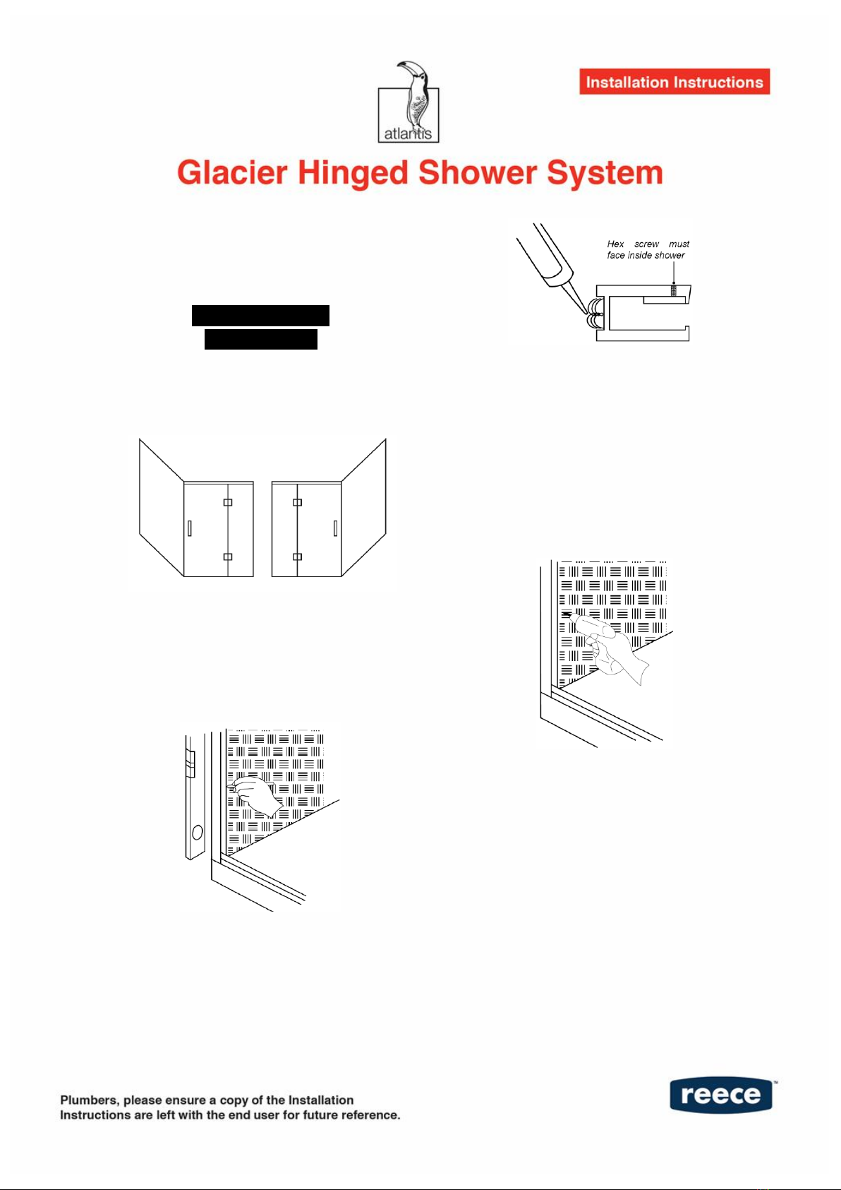
GLASS RECEIVER CHANNEL MUST BE
INSTALLED ONTO THE WATERPROOFING
BEFORE THE WALLS ARE TILED
INSTRUCTIONS FOR
2 WALL SYSTEM
1. Choose door location.
2. Position the glass receiver channels over
the base glazing channels. Mark the wall
to indicate where the wall channels are
plumb.
3. Mask two sides of wall channel before
applying white silicon. Apply a continuous
8mm bead of white silicon to full length of
wall channels in groove as indicated.
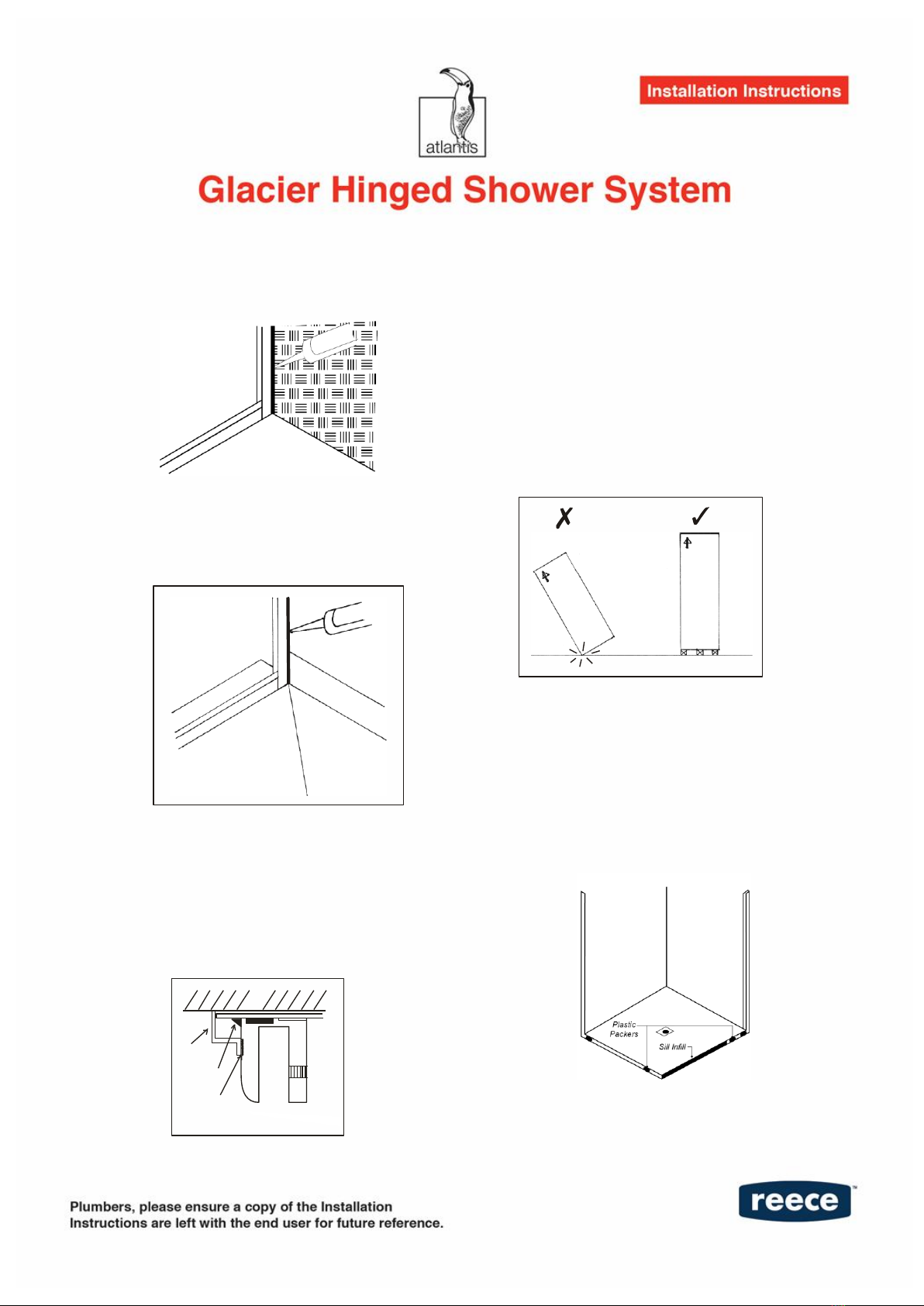
4. Ensure the glass receiver channels are
located firmly over the base glazing
channels. Locate the framing timber. Use
the 4mm drill bit to drill holes through the
glass receiver channels. Fix four screws
through the channels into the wall
framing (use wall plugs if required
supplied with wall channels).
Apply a 10mm continuous bead of Sika
Artic White silicon, to the full length of
each wall channel. Silicon seal the join
where the wall and base channel will
intersect.