REED 00 MODEL: C50SS
TRAILER CONCRETE PUMP
OPER.
PAGE 05
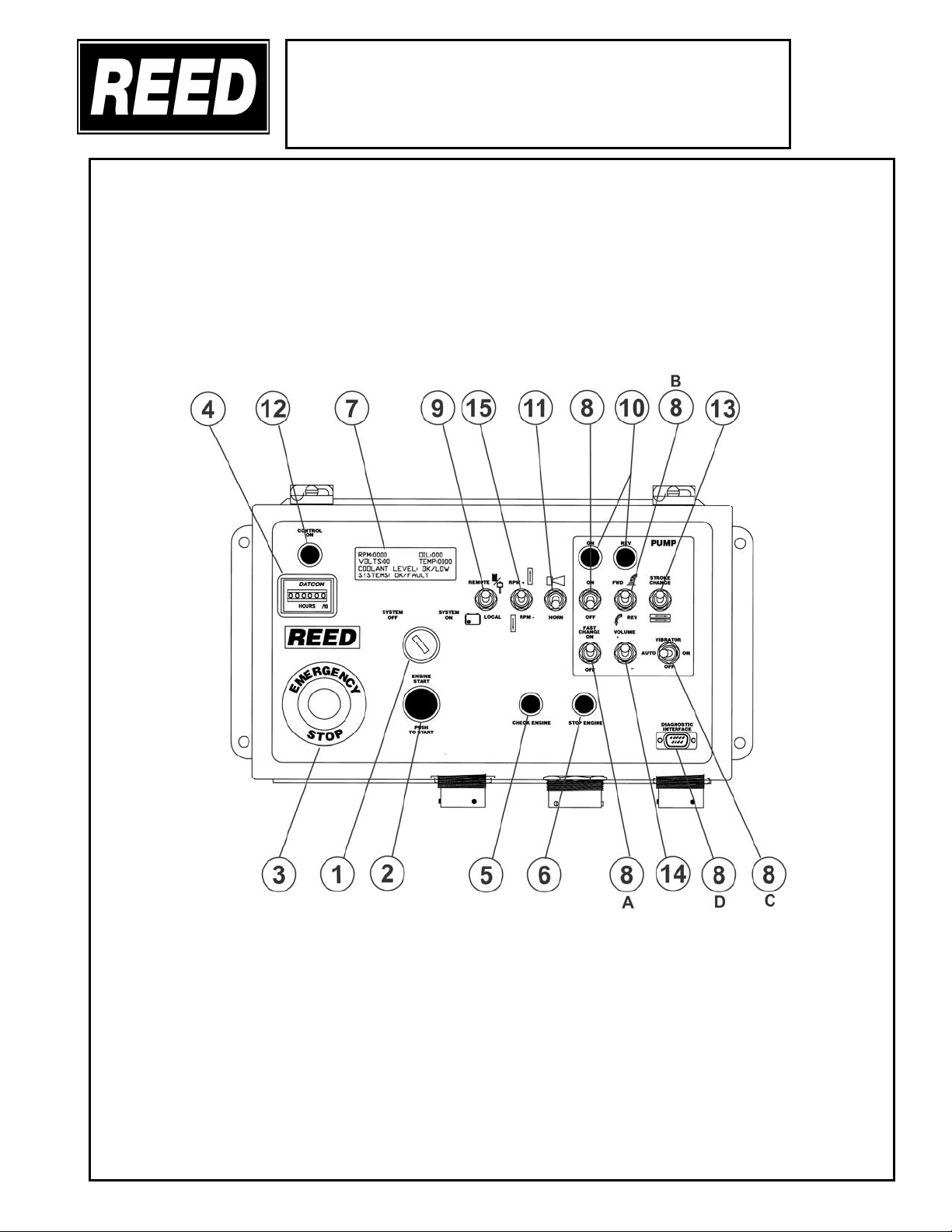
9. CONTROL SWITCH
This is a two (2) position toggle switch and is used to select the pump control
location. Move toggle to LOCAL to enable operation of concrete pump from main
stationary panel. Move toggle to REMOTE for operation using the remote control.
10. INDICATOR LIGHTS RELATED TO THE PUMP (GREEN LIGHT)
These green lights, located above and below the switches are used, when lit, to
indicate the position of the toggles.
11. HORN/RESET
This is a momentary toggle switch and is used to reactivate the control and pump
circuit after machine has been shut down using the EMERGENCY STOP switch.
Once the emergency stop has been depressed it will be necessary to pull out switch
and move toggle of HORN switch momentary to RESET position.
12. CONTROL ON INDICATOR (GREEN LIGHT)
This is a green indicator light, when lit denotes control circuit is energized.
13. STROKE CHANGE SWITCH
This switch is a two (2) position spring return switch and has two functions. One is
A momentary toggle to change stroke from one side to the other to help clear a
possible line plug. The other function is when the switch is held DOWN and allow
for end of stroke. High pressure check or in ths instance of equalizing the stroking
pistons. The allowance of the spring return sets the machine back in forward stroke.
14. VOLUME CONTROL (C-SERIES ONLY CLOSED LOOP HYD SYSTEM)
This control is installed on the discharge port of the main hydraulic pump. It is used
to adjust volume OUTPUT of the material cylinders which in turn is controlled by the
hydraulic pump. Flipping toggle switch UPWARD will INCREASE volume, flipping
toggle switch DOWNWARD will DECREASE volume.
15. THROTTLE CONTROL-TOGGLE SWITCH
This is a three (3) position spring centered switch and is used to adjust the engine
RPM. Toggle UP to INCREASE engine speed. Toggle DOWN to DECREASE
engine speed. Speed of engine will retained as set until RESET.
16. STROKE COUNTER (OPTION-NOT SHOWN)
This digital indicator is used to indicate the amount of stokes per minute the concrete
pump is producing.
REVISION: