Reely TRX-4 User manual

6 Montage der Beleuchtung
Da jedes Modell individuell aufgebaut und gestaltet ist, können zum Einbau der Beleuch-
tung nur allgemeine Hinweise gegeben werden.
Montieren Sie die Anschlusskabel und LEDs mit geeigneten Hilfsmitteln (z. B. mit Kabelbin-
dern, Klebepads) an Ihrem Chassis oder der Karosserie. Für die LEDs müssen an den ange-
dachten Einbauorten entsprechende Löcher gebohrt werden.
Verlegen Sie die Kabel und LEDs in der Art, dass diese nicht in bewegliche/rotierende Antriebs-
teile und/oder Räder gelangen können. Bewegliche Fahrwerksteile dürfen nicht an den Kabeln
scheuern (z.B. beim Ein-/ Ausfedern der Räder bzw. beim Lenken).
In der Praxis hat es sich bewährt, dass die Anschlussmodule auf der Innenseite vom Dach der
Karosserie z. B. mit einem doppelseitigem Klebepad montiert und alle Kabel der LEDs dorthin
geführt werden.
6.1 Inbetriebnahme
Bei Anschluss aller verfügbaren LEDs aus dem Lieferumfang wird die Empfänger-
stromversorgung mit einem Strom von ca. 500 mA belastet. Erfolgt die Stromversor-
gung des LED-Systems aus einem BEC des Fahrtreglers, so sollte die Belastbarkeit
des BEC bei mindestens 3 A Dauerstrom sein. Andernfalls könnte es aufgrund von
Spannungseinbrüchen durch den zusätzlichen Strombedarf des Lenkservos im
Fahrbetrieb zu Störungen in der Empfangsanlage kommen.
Das BEC des Fahrtreglers bzw. die Empfängerstromversorgung (Empfängerakku)
darf keinesfalls eine Ausgangsspannung von mehr als 6 V/DC haben. Andernfalls
wird die Elektronik des LED-Systems und/oder die LEDs zerstört. Verlust der Ge-
währleistung/Garantie!
Bitte überprüfen Sie vor der Installation, ob alle Teile in der Verpackung sind.
Bringen Sie die richtigen Leuchten an den entsprechenden Stellen an.
Schließen Sie die Beleuchtungsdrähte ordnungsgemäß nach Anleitung an die Lichtsteu-
erung an.
Verlegen Sie die Kabel sauber.
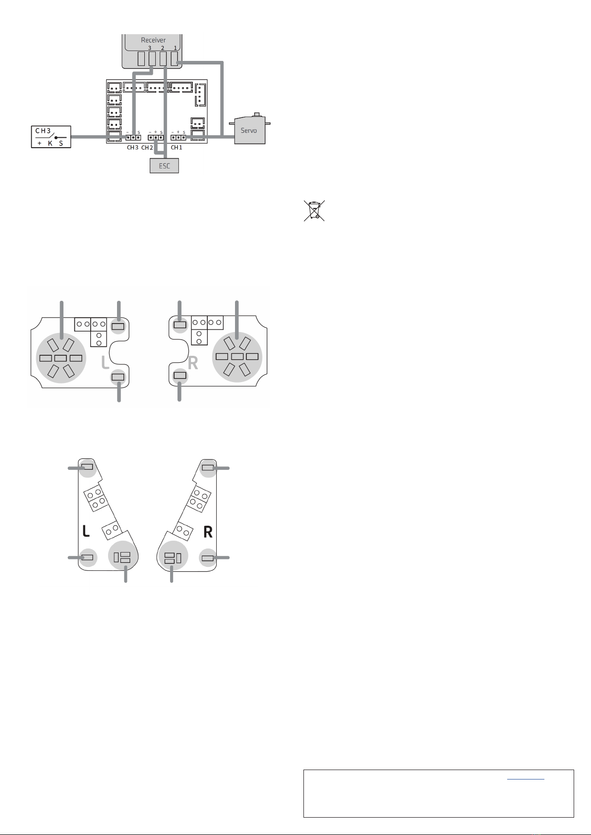
Schließen Sie die Lichtsteuerung an den RC-Empfänger an, dann verbinden Sie den Rich-
tungskanal (Lenkservo) des Empfängers und den Servoanschluss mit CH1.
Verbinden Sie den Gaskanal (Fahrregler/ESC) des Empfängers und den ESC-Anschluss
mit CH2.
Verlegen Sie die Kabel und LEDs in der Art, dass diese nicht in bewegliche/rotierende
Antriebsteile und/oder Räder gelangen können. Bewegliche Fahrwerksteile dürfen nicht an
den Kabeln scheuern (z. B. beim Ein-/Ausfedern der Räder bzw. beim Lenken).
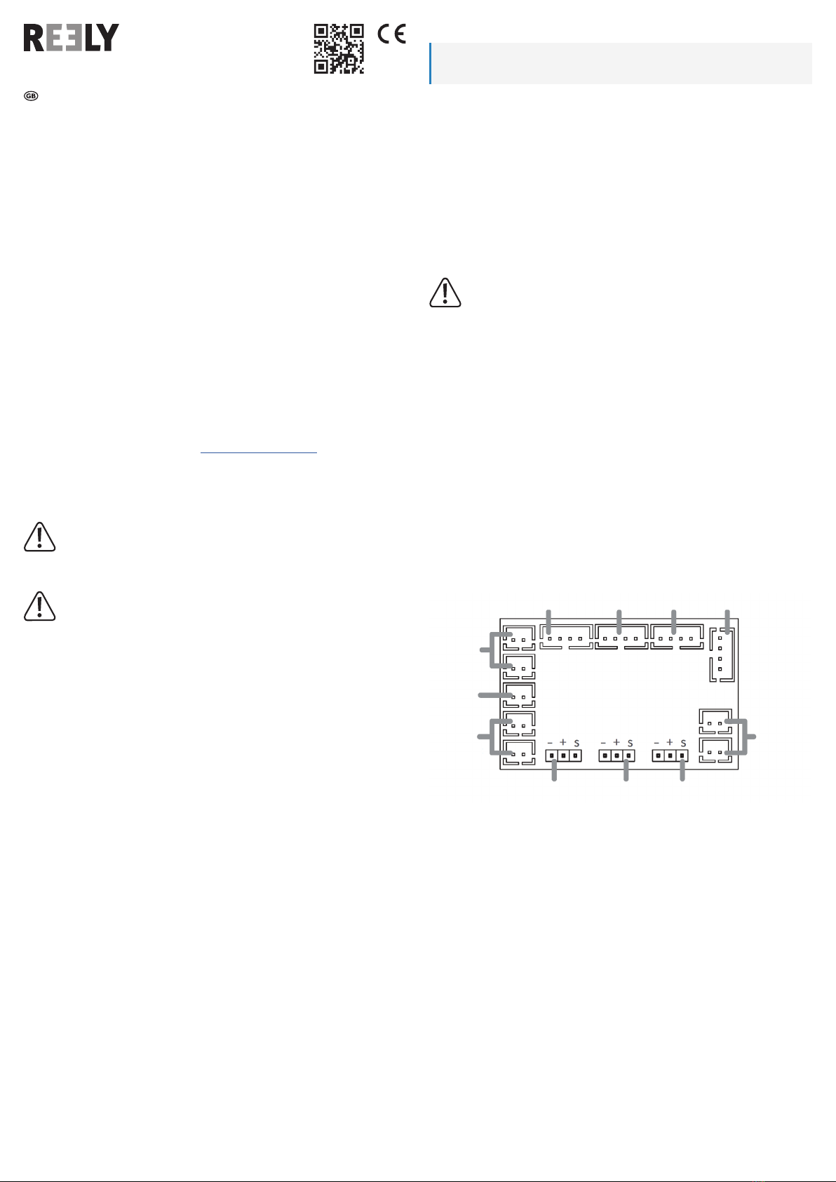
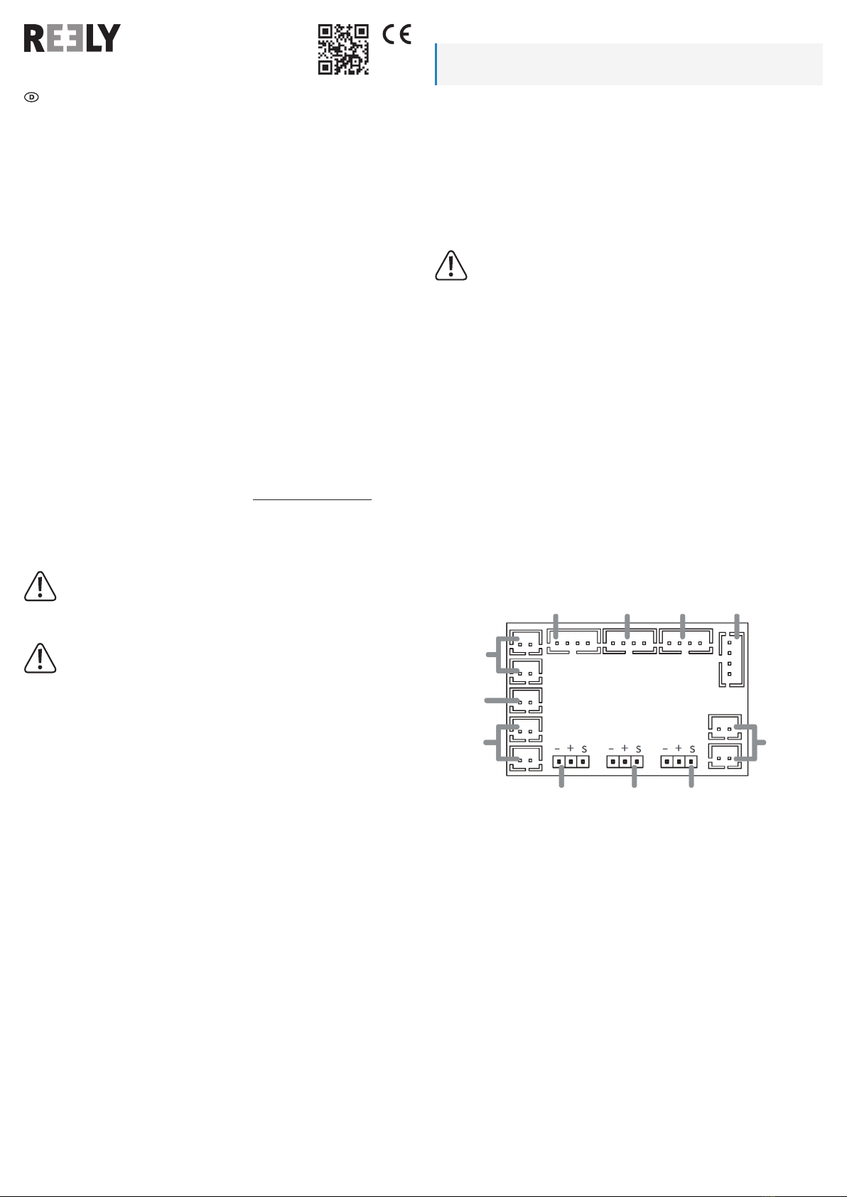
6.2 Anschlussbelegung der Lichtsteuerung
1 Rücklicht (links)
2 Rücklicht (rechts)
3 Scheinwerfer (rechts)
4 Scheinwerfer (links)
5 Radkastenbeleuchtung „Downlight“
(optional erhältlich)
6 CH1 Lenkservo (wird mit dem Y-Kabel mit
dem Empfänger verbunden)
7 CH2 Fahrregler/ESC (wird mit dem
Y-Kabel mit dem Empfänger verbunden)
8 CH3 Taster oder Sonderkanal für
Dachscheinwerfer (Umschalten des
Lichtmodus)
9 Dachscheinwerfer LEDs „blau“ (optional
erhältlich)
10 Dachscheinwerfer LED „weiß“ (optional
erhältlich)
11 Dachscheinwerfer LEDs „rot“ (optional
erhältlich)
1 2 43
9
8 7 6
5
11
10
Bedienungsanleitung
TRX-4 Beleuchtungs-Set
Best.-Nr. 2533617
1 Bestimmungsgemäße Verwendung
Das Produkt dient als Effektbeleuchtung für Modellfahrzeuge. Die LED Beleuchtung wird an-
schlussfertig ausgeliefert. Die Anschlusskabel der einzelnen LED-Paare sind mit verpolungs-
sicheren Steckern versehen. Die Stromversorgung der LEDs erfolgt aus der Empfängerstrom-
versorgung (BEC oder Empfängerakku).
Aus Sicherheits- und Zulassungsgründen dürfen Sie das Produkt nicht umbauen und/oder
verändern. Falls Sie das Produkt für andere Zwecke verwenden als zuvor beschrieben, kann
das Produkt beschädigt werden. Außerdem kann eine unsachgemäße Verwendung Gefahren
wie z. B. Kurzschluss, Brand, etc. hervorrufen. Lesen Sie sich die Bedienungsanleitung genau
durch und bewahren Sie diese auf. Reichen Sie das Produkt nur zusammen mit der Bedie-
nungsanleitung an dritte Personen weiter.
Das Produkt entspricht den gesetzlichen, nationalen und europäischen Anforderungen. Alle
enthaltenen Firmennamen und Produktbezeichnungen sind Warenzeichen der jeweiligen In-
haber. Alle Rechte vorbehalten.
2 Lieferumfang
Lichtsteuerung
2x Scheinwerferlicht
2x Rücklicht
2x Verlängerungskabel für Servos
2x Servo Y-Kabel (lang)
2x Doppelseitiges Klebeband
Schrauben Set
Bedienungsanleitung
3 Neueste Informationen zum Produkt
Laden Sie die neuesten Produktinformationen unter www.conrad.com/downloads herunter
oder scannen Sie den abgebildeten QR-Code. Folgen Sie den Anweisungen auf der Website.
4 Symbole in diesem Dokument
Folgende Symbole benden sich auf dem Produkt/Gerät oder im Text:
Das Symbol mit dem Ausrufezeichen im Dreieck weist auf wichtige Informationen
in dieser Bedienungsanleitung hin. Lesen Sie diese Informationen immer aufmerk-
sam.
5 Sicherheitshinweise
Lesen Sie sich die Bedienungsanleitung sorgfältig durch und beachten Sie
insbesondere die Sicherheitshinweise. Bei Schäden, die durch Nichtbeachten
dieser Bedienungsanleitung verursacht werden, erlischt die Gewährleistung/
Garantie! Für Folgeschäden übernehmen wir keine Haftung!
Bei Sach- oder Personenschäden, die durch unsachgemäße Handhabung
oder Nichtbeachten der Sicherheitshinweise verursacht werden, übernehmen
wir keine Haftung. In solchen Fällen erlischt die Gewährleistung/Garantie.
Aus Sicherheits- und Zulassungsgründen ist das eigenmächtige Umbauen und/oder Ver-
ändern des Produktes nicht gestattet.
Das Produkt darf nicht feucht oder nass werden. Kurzschlussgefahr! Verlust von Gewähr-
leistung/Garantie!
Das Produkt ist kein Spielzeug, es gehört nicht in Kinderhände.
Die LEDs sind nur zum direkten Anschluss an das LED-System geeignet. Bei anderer
Verschaltung/Verwendung/Nichtbeachtung werden die LEDs zerstört. Verlust von Gewähr-
leistung/Garantie!
Achtung! LED-Licht: Nicht direkt in den LED-Lichtstrahl blicken oder direkt mit optischen
Instrumenten betrachten!
Achten Sie bei der Montage der LEDs und der Anschlusskabel darauf, dass Kabel/LEDs
nicht in bewegliche/rotierende Antriebsteile und/oder Räder gelangen können.
Gehen Sie vorsichtig mit dem Produkt um, durch Stöße, Schläge oder dem Fall aus bereits
geringer Höhe wird es beschädigt.
Lassen Sie das Verpackungsmaterial nicht achtlos liegen, dieses könnte für Kinder zu ei-
nem gefährlichen Spielzeug werden.
Sollten sich Fragen ergeben, die nicht mit Hilfe der Bedienungsanleitung abgeklärt werden
können, so setzen Sie sich bitte mit uns oder einem anderen Fachmann in Verbindung.
Lassen Sie Wartungs-, Anpassungs- und Reparaturarbeiten ausschließlich von einem
Fachmann bzw. einer Fachwerkstatt durchführen.

Erklärung der Abkürzungen
B = blau W = weiß R = rot
1. Der Dachscheinwerfer bleibt eingeschaltet, wenn das Gerät eingeschaltet ist.
2. BRWBR: BR und WBR blinken abwechselnd zur gleichen Zeit.
3. BBWRR: BB und RR blinken abwechselnd gleichzeitig und W bleibt eingeschaltet.
4. BBWRR: BB und RR blinken abwechselnd 4-mal und W bleibt eingeschaltet; BBWRR
blinkt 3-mal schnell.
5. BRWBR: W blinkt schnell in Atemzügen, BR und BR blinken abwechselnd gleichzeitig und
W bleibt eingeschaltet.
6. Zyklus-Modus: Alle Lichter blinken abwechselnd von links nach rechts und dann abwech-
selnd von rechts nach links.
7. BBWRR: BB-Pulsierend, dann RR-Pulsierend, und W bleibt an.
8. Anzeigemodus: Anzeige aller Modi des Dachscheinwerfers.
9. Lichter ausschalten.
8 Entsorgung
Alle Elektro- und Elektronikgeräte, die auf den europäischen Markt gebracht wer-
den, müssen mit diesem Symbol gekennzeichnet werden. Dieses Symbol weist da-
rauf hin, dass dieses Gerät am Ende seiner Lebensdauer getrennt von unsortiertem
Siedlungsabfall zu entsorgen ist.
Jeder Besitzer von Altgeräten ist verpichtet, Altgeräte einer vom unsortierten
Siedlungsabfall getrennten Erfassung zuzuführen. Die Endnutzer sind verpichtet,
Altbatterien und Altakkumulatoren, die nicht vom Altgerät umschlossen sind, sowie
Lampen, die zerstörungsfrei aus dem Altgerät entnommen werden können, vor der
Abgabe an einer Erfassungsstelle vom Altgerät zerstörungsfrei zu trennen.
Vertreiber von Elektro- und Elektronikgeräten sind gesetzlich zur unentgeltlichen Rücknahme
von Altgeräten verpichtet. Conrad stellt Ihnen folgende kostenlose Rückgabemöglichkeiten
zur Verfügung (weitere Informationen auf unserer Internet-Seite):
in unseren Conrad-Filialen
in den von Conrad geschaffenen Sammelstellen
in den Sammelstellen der öffentlich-rechtlichen Entsorgungsträger oder bei den von Her-
stellern und Vertreibern im Sinne des ElektroG eingerichteten Rücknahmesystemen
Für das Löschen von personenbezogenen Daten auf dem zu entsorgenden Altgerät ist der
Endnutzer verantwortlich.
Beachten Sie, dass in Ländern außerhalb Deutschlands evtl. andere Pichten für die Altgeräte-
Rückgabe und das Altgeräte-Recycling gelten.
9 Technische Daten
9.1 Spannungsversorgung
Betriebsspannung......................... 4,8 - 5,5 V/DC
Stromaufnahme............................ max. 500 mA
9.2 Anschlüsse und Funktionen
Steckersystem.............................. Futaba
Anzahl der RC-Kanäle.................. 3 (2 wenn der Taster an der Lichtsteuerung
...................................................... verwendet wird)
9.3 Umgebungsbedingungen
Abmessungen
LED-Anschlussmodul ................... 45 x 29 x 10 mm (L x B x H)
Gewicht......................................... ca. 135 g
Lagertemperatur........................... -20 °C bis +70 °C,
...................................................... relative Luftfeuchtigkeit 20% bis 90%, nicht kondensierend
Betriebstemperatur....................... 0 °C bis +70 °C,
...................................................... relative Luftfeuchtigkeit 30% bis 90%, nicht kondensierend
6.3 Anschluss am Empfänger, Fahrregler (ESC), Lenkservo und
Taster/Sonderkanal
CH1: Beide Enden des Kabelbaums werden mit dem Servo bzw. CH1 der Hauptsteuerplatine
verbunden.
CH2: Beide Enden der Verbindungsleitung werden an den Fahrregler (ESC) bzw. an CH2 der
Hauptsteuerplatine angeschlossen.
CH3: Der Schalter für die Dachscheinwerfer (optional erhältlich) wird direkt an den „+/s“-
Anschluss von CH3 der Hauptplatine angeschlossen. Der Schalter kann die Lichteffekte des
Dachscheinwerfers steuern. Wenn Ihre Fernsteuerung Kanal 3 und Kanal 4 unterstützt, dann
schließen Sie mit Kanal 3 oder Kanal 4 die Lichtsteuerung über eine Verbindungsleitung an
Ihren Empfänger an diesen Schaltkanal an. Dann können Sie die Lichteffekte über den ent-
sprechenden Kanal steuern.
1 Scheinwerfer (links)
2 Nebelscheinwerfer (links)
3 Richtungsanzeige/Blinker (links)
4 Nebelscheinwerfer (rechts)
5 Scheinwerfer (rechts)
6 Richtungsanzeige/Blinker (rechts)
1 Bremslicht (links)
2 Richtungsanzeige/Blinker (links)
3 Rückleuchte/Rückfahrscheinwerfer (links)
4 Rückleuchte/Rückfahrscheinwerfer (rechts)
5 Richtungsanzeige/Blinker (rechts)
6 Bremslicht (rechts)
7 Betriebsarten der LEDs
Die Funktion der LED-Anschlüsse für die Blinker sowie die Bremslicht- und Rückfahrschein-
werfer funktionieren immer und unabhängig vom Dachscheinwerfer.
Betätigen Sie am Sender die Lenkung nach links, werden die LEDs am Anschluss L so lange
blinken, bis das Steuersignal sich wieder in der Neutralstellung bendet. Steuern Sie nach
rechts, so blinken die LEDs am Anschluss R.
Fahren Sie vorwärts und bremsen (Steuerhebel am Sender Richtung „Rückwärts“), so leuchten
das Bremslicht. Wenn Sie jetzt den Steuerhebel für vorwärts/rückwärts wieder in die Neutral-
stellung bringen, erlischt das Bremslicht. Fahren Sie rückwärts, so leuchten die weißen LEDs
des Rückfahrscheinwerfers.
7.1 Dachscheinwerfer (optional erhältlich)
Es gibt 9 Modi für den Dachscheinwerfer. Wählen Sie die Modi durch mehrfaches Drücken
des Tasters oder den entsprechenden Empfängerkanal, der an CH3 der Lichtsteuerung an-
geschlossen ist.
Dies ist eine Publikation der Conrad Electronic SE, Klaus-Conrad-Str. 1, D-92240 Hirschau (www.conrad.com).
Alle Rechte einschließlich Übersetzung vorbehalten. Reproduktionen jeder Art, z. B. Fotokopie, Mikroverlmung, oder
die Erfassung in elektronischen Datenverarbeitungsanlagen, bedürfen der schriftlichen Genehmigung des Herausgebers.
Nachdruck, auch auszugsweise, verboten. Die Publikation entspricht dem technischen Stand bei Drucklegung.
Copyright 2022 by Conrad Electronic SE. *2533617_V2_0622_02_m_VTP_DE
1
2
5
34
6
1 2 4 5
3 6

6 Installing the lighting set
Every model has its peculiar construction and design; we can thus only provide general
information for the lighting set installation.
Use appropriate tools (such as cable ties and adhesive pads) to attach the connection cables
and LEDs to the chassis or body. For the LEDs, you need to drill appropriate holes at the
corresponding locations.
Place the LEDs and connection cables so that they do not interfere with moving/rotating drive
parts and wheels. The chassis’ moving parts must not rub against the cables (for example,
when the wheels deect/bounce back or during steering).
It is good practice to attach the connection module to the inside of the top, using, for example,
a double-sided adhesive pad, and to route all the LED cables there.
The LEDs of the roof-mounted headlight can be arranged individually to your personal prefe-
rence. The manufacturer recommends the following order: 2x “blue” LEDs, 1x “white” LED, 2x
“red” LEDs.
6.1 Getting started
When all available LEDs from the delivered items are connected, the receiver’s
current load is approx. 500 mA. If the power supply of the LED system comes from a
BEC of the speed controller, the load capacity of the BEC should be at least 3 A con-
tinuous current. Otherwise, voltage drops resulting from the additional power requi-
rement of the steering servo during driving may cause the receiver to malfunction.
An output voltage of the BEC of the speed controller or the receiver power supply
(receiver battery) must never exceed 6 V/DC. Otherwise, this may permanently
damage the electronics of the LED system or LEDs. This will void the warranty/
guarantee.
Please check the package contents for completeness before installation.
Attach the lights correctly to their respective locations.
Connect the lighting wires correctly to the light control according to the instructions.
Arrange the cables neatly.
Connect the light control to the RC receiver; then connect the receiver’s direction channel
(steering servo) and the servo connector to CH1.
Connect the receiver’s throttle channel (speed control/ESC) and the ESC connector to
CH2.
Place the LEDs and connection cables so that they do not interfere with moving/rotating
drive parts and wheels. The chassis’ moving parts must not rub against the cables (e.g.,
when the wheels deect/bounce back or during steering).
6.2 Pin assignment of the light control
1 Tail light (left)
2 Tail light (right)
3 Headlight (right)
4 Headlight (left)
5 Wheel case “downlight” (optionally
available)
6 CH1 steering servo (connected to the
receiver using a Y-cable)
7 CH2 speed controller/ESC (connected to
the receiver using a Y-cable)
8 CH3 push-button or special channel for
roof-mounted headlights (light mode
switching)
9 Roof-mounted headlight “blue” LEDs (opti-
onally available)
10 Roof-mounted headlight “white” LED
(optionally available)
11 Roof-mounted headlight “red” LEDs
(optionally available)
1 2 43
9
8 7 6
5
11
10
Operating instructions
TRX-4 Lighting Set
Item no. 2533617
1 Intended use
The product serves as decorative lighting for model vehicles. The LED lighting is delivered
ready for connection. The connection cables of the individual LED pairs are tted with reverse
polarity protected connectors. The LEDs are powered by the receiver (BEC or receiver battery).
For safety and approval purposes, do not rebuild and/or modify this product. Using the product
for purposes other than those described above may damage the product. In addition, improper
use can cause hazards such as a short circuit or re. Read the operating instructions carefully
and store them in a safe place. Only make this product available to third parties together with
its operating instructions.
This product complies with statutory, national and European regulations. All company and pro-
duct names contained herein are trademarks of their respective owners. All rights reserved.
2 Delivery content
Light control
2x headlights
2x tail lights
2x extension cables for servos
2x Y-type servo cables (long)
2x double-sided adhesive tapes
Screw set
Operating instructions
3 Latest product information
Download the latest product information at www.conrad.com/downloads or scan the QR code
shown. Follow the instructions on the website.
4 Symbols in this document
The following symbols appear on the product/device or in the text:
The symbol with the exclamation mark in the triangle is used to indicate important
information. Always read this information carefully.
5 Safety information
Read the operating instructions carefully and especially observe the safety
information. Damage caused due to failure to observe these instructions will
void the warranty! We shall not be liable for any consequential damage!
We shall not be liable for damage to property or personal injury caused by
improper handling or failure to observe the safety information! Such cases
will void the warranty/guarantee.
For safety and licensing reasons, unauthorised conversion and/or modications to the pro-
duct are not permitted.
The product must not get damp or wet. There is a risk of a short circuit! This will void the
warranty/guarantee!
The product is not a toy and must be kept out of the reach of children.
The LEDs should only be connected directly to the LED system. Any other wiring/connec-
tion or misuse of the LEDs may permanently damage them. This will void the warranty/
guarantee!
Attention! LED light: do not look into the beam directly or through optical instruments!
When installing the LEDs and connection cables, ensure that they do not touch moving/
rotating drive parts and wheels.
Handle the product with care. Jolts, impacts or a fall even from a low height may damage
the product.
Do not leave packaging material lying around carelessly, as it could become a dangerous
plaything for children.
If you have any questions that are not answered by these operating instructions, contact us
or an experienced technician.
Maintenance, modications and repairs must be carried out by a technician or a specialist
repair centre.

Explanation of abbreviations
B = blue W = white R = red
1. The roof-mounted headlight remains on when the unit is switched on.
2. BRWBR: BR and WBR ash alternately at the same time.
3. BBWRR: BB and RR ash alternately at the same time and W remains on.
4. BBWRR: BB and RR ash alternately 4 times and W remains on; BBWRR ashes rapidly
3 times.
5. BRWBR: W ashes rapidly in breaths; BR and BR ash alternately at the same time and
W remains on.
6. Cycle mode: All lights ash alternately from left to right and then alternately from right to left.
7. BBWRR: BB pulsing, then RR pulsing, and W remains on.
8. Display mode: All modes of the roof-mounted headlight are displayed.
9. Switch off the lights.
8 Disposal
All electrical and electronic equipment placed on the European market must be
labelled with this symbol. This symbol indicates that this device should be disposed
of separately from unsorted municipal waste at the end of its service life.
Owners of WEEE shall dispose of it separately from unsorted municipal waste.
Spent batteries and accumulators, which are not enclosed by the WEEE, as well
as lamps that can be removed from the WEEE in a non-destructive manner, must
be removed by end users from the WEEE in a non-destructive manner before it is
handed over to a collection point.
Distributors of electrical and electronic equipment are legally obliged to provide free take-back
of waste. Conrad provides the following return options free of charge (more details on our
website):
at our Conrad stores
at the collection points established by Conrad
at the collection points of public waste disposal agencies or at the collection systems set up
by manufacturers and distributors in accordance with the German Electrical and Electronic
Equipment Act.
The end user is responsible for deleting personal data from the WEEE to be disposed of.
It should be noted that different obligations about the return or recycling of WEEE may apply in
countries outside of Germany.
9 Technical data
9.1 Power supply
Operating voltage ......................... 4.8 – 5.5 V/DC
Current consumption .................... max. 500 mA
9.2 Connections and functions
Connector system......................... Futaba
Number of RC channels ............... 3 (2 when using the push-button on the
...................................................... light control)
9.3 Ambient conditions
LED connection
module dimensions....................... 45 x 29 x 10 mm (L x W x H)
Weight .......................................... approx. 135 g
Storage temperature..................... -20 °C to +70 °C,
...................................................... 20% to 90% relative humidity, non-condensing
Operating temperature ................. 0 °C to +70 °C,
...................................................... 30% to 90% relative humidity, non-condensing
6.3 Connecting to the receiver, speed controller (ESC), steering servo and
push-button/special channel
CH1: Both ends of the wiring harness are connected to the servo or CH1 of the main control
board.
CH2: Both ends of the connection cable are connected to the speed controller (ESC) or CH2
of the main control board.
CH3: The switch for the roof-mounted headlights (optionally available) is connected directly to
the “+/s” connection of CH3 of the main control board. The switch controls the lighting effects
of the roof-mounted headlight. If your remote control supports Channel 3 and Channel 4, use
these channels to connect the light control to this switch channel on your receiver via a connec-
tion cable. Then you will be able to control the lighting effects using the corresponding channel.
1 Headlight (left)
2 Fog light (left)
3 Direction indicator/turn signal (left)
4 Fog light (right)
5 Headlight (right)
6 Direction indicator/turn signal (right)
1 Brake light (left)
2 Direction indicator/turn signal (left)
3 Tail light/reverse light (left)
4 Tail light/reverse light (right)
5 Direction indicator/turn signal (right)
6 Brake light (right)
7 LED modes
The LED connections of the turn signals, brake and reverse lights always function independent-
ly of the roof-mounted headlight.
Steering to the left on the transmitter causes the LEDs on connection L to ash until the control
signal is neutral again. Steering to the right causes the LEDs on connection R to ash.
Engaging the brake during the forward travel (by pushing the control lever on the transmitter to
“reverse”) causes the brake light to come on. Moving the forward/reverse control lever back to
the neutral position causes the brake light to go out. During the reverse travel, the white LEDs
of the reverse light come on.
7.1 Roof-mounted headlights (optionally available)
The roof-mounted headlight has 9 modes. You can select the desired modes by pressing the
push-button several times or using the respective receiver channel connected to CH3 of the
light control.
1
2
5
34
6
1 2 4 5
3 6
This is a publication by Conrad Electronic SE, Klaus-Conrad-Str. 1, D-92240 Hirschau (www.conrad.com).
All rights including translation reserved. Reproduction by any method (e.g. photocopying, microlming or capturing in elec-
tronic data processing systems) requires prior written approval from the publisher. Reprinting, also in part, is prohibited.
This publication reects the technical status at the time of printing.
Copyright 2022 by Conrad Electronic SE. *2533617_V2_0622_02_m_VTP_GB
This manual suits for next models
1
Table of contents
Languages:
Other Reely Automobile Accessories manuals