8© 2013, 2023 Regal Rexnord Corporation, All Rights Reserved. MCIM23014E • Form# CP3-001E
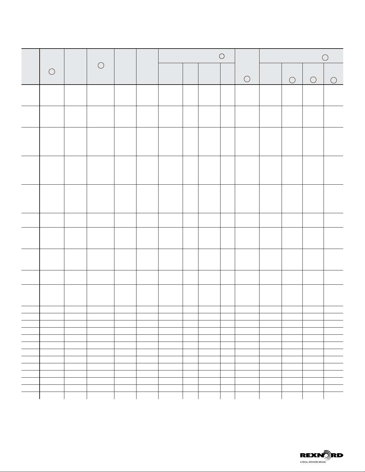
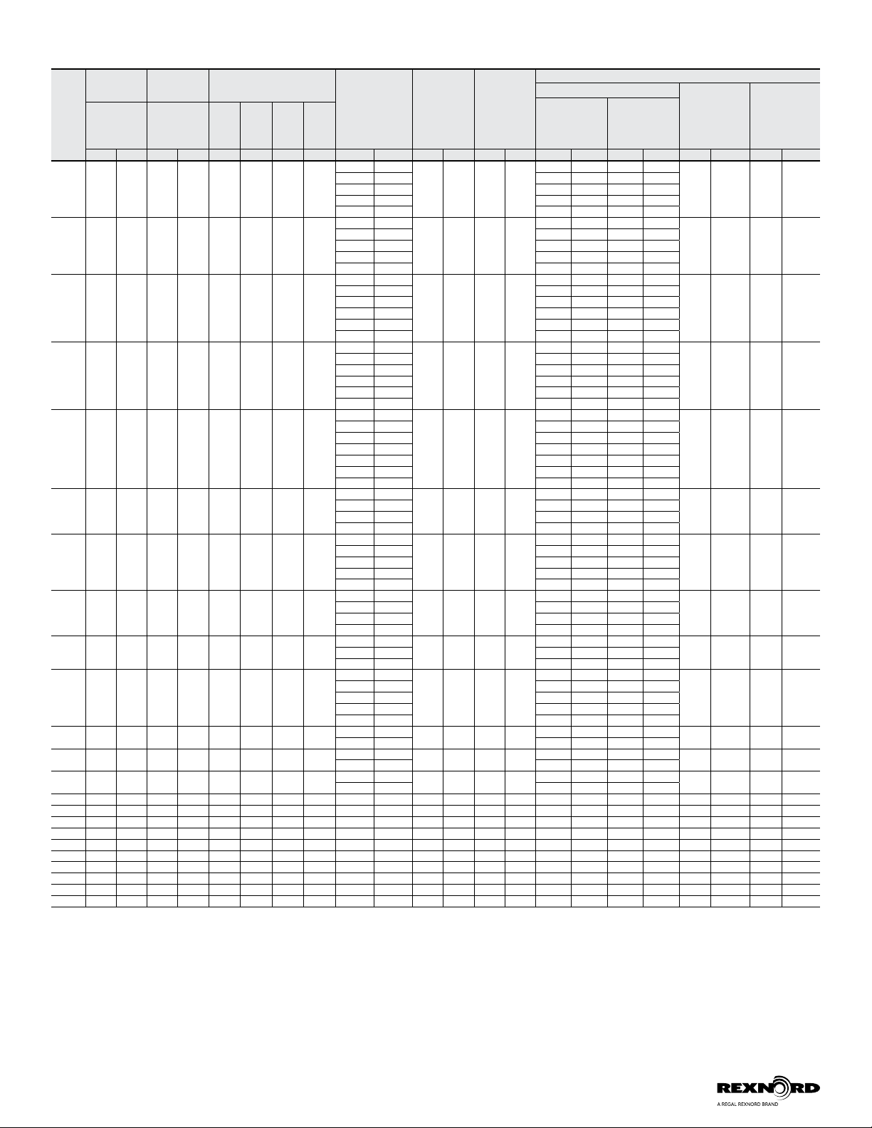
Table 3 — Alignment Values
XTSR
71
Size
“A”
Dimension
“A”
Dimension
“N”
Dimension “C” Length
(distance
between hub
flanges)
Installation
Axial Limits
+/-
Axial
Capacity
+/-
Recommended Installation Limits***
Parallel Misalignment Angular
Misalignment
Between Hubs
Installation
(X-Y)
Standard Hub
Angular
Misalignment
Between Hubs
Installation
(X-Y)
XL Hub
Parallel
Alignment Total
Indicator Read-
ing (TIR*)
Installation
Limit Parallel
Offset
“P”**
Std. Hub XL Hub Min. Max. Min. Max.
(in) (mm) (in) (mm) (in) (in) (mm) (mm) (in) (mm) (in) (mm) (in) (mm) (in) (mm) (in) (mm) (in) (mm) (in) (mm)
494 2.77 70.0 3.36 85.0 0.33 0.35 8.3 8.8
3.50 88.9
0.012 0.30 0.045 1.2
0.035 0.89 0.018 0.44
0.004 0.10 0.004 0.10
3.75 95.3 0.038 0.95 0.019 0.48
5.00 127.0 0.050 1.27 0.025 0.64
3.94 100.0 0.039 1.00 0.020 0.50
5.51 140.0 0.055 1.40 0.028 0.70
644 3.36 85.0 --- --- 0.33 0.35 8.3 8.8
3.50 88.9
0.017 0.43 0.068 1.7
0.035 0.89 0.018 0.44
0.004 0.10 --- ---
3.75 95.3 0.038 0.95 0.019 0.48
5.00 127.0 0.050 1.27 0.025 0.64
3.94 100.0 0.039 1.00 0.020 0.50
5.51 140.0 0.055 1.40 0.028 0.70
726 3.74 95.0 4.25 108.0 0.33 0.35 8.3 8.8
3.50 88.9
0.026 0.65 0.051 1.3
0.028 0.71 0.014 0.36
0.005 0.13 0.006 0.15
3.75 95.3 0.030 0.76 0.015 0.38
4.38 111.1 0.035 0.89 0.018 0.44
5.00 127.0 0.040 1.02 0.020 0.51
3.94 100.0 0.031 0.80 0.016 0.40
5.51 140.0 0.044 1.12 0.022 0.56
826 4.25 108.0 5.08 129.0 0.36 0.38 9.1 9.6
3.50 88.9
0.030 0.75 0.059 1.5
0.028 0.71 0.014 0.36
0.006 0.15 0.007 0.18
3.75 95.3 0.030 0.76 0.015 0.38
4.38 111.1 0.035 0.89 0.018 0.44
5.00 127.0 0.040 1.02 0.020 0.51
3.94 100.0 0.031 0.80 0.016 0.40
5.51 140.0 0.044 1.12 0.022 0.56
996 5.08 129.0 5.51 140.0 0.37 0.39 9.3 9.9
3.75 95.3
0.035 0.90 0.070 1.8
0.030 0.76 0.015 0.38
0.007 0.18 0.008 0.20
4.38 111.3 0.035 0.89 0.018 0.45
5.00 127.0 0.040 1.02 0.020 0.51
7.00 177.8 0.056 1.42 0.028 0.71
3.94 100.0 0.031 0.80 0.016 0.40
5.51 140.0 0.044 1.12 0.022 0.56
7.09 180.0 0.057 1.44 0.028 0.72
1088 5.51 140.0 6.54 166.0 0.40 0.42 10.1 10.7
5.00 127.0
0.025 0.65 0.051 1.3
0.020 0.51 0.010 0.25
0.005 0.13 0.006 0.15
7.00 177.8 0.028 0.71 0.014 0.36
5.51 140.0 0.022 0.56 0.011 0.28
7.09 180.0 0.028 0.72 0.014 0.36
1298 6.54 166.0 7.83 199.0 0.50 0.52 12.6 13.3
5.00 127.0
0.031 0.80 0.061 1.6
0.020 0.51 0.010 0.25
0.006 0.15 0.008 0.20
7.00 177.8 0.028 0.71 0.014 0.36
5.51 140.0 0.022 0.56 0.011 0.28
7.09 180.0 0.028 0.72 0.014 0.36
9.84 250.0 0.039 1.00 0.020 0.50
1548 7.83 199.0 8.66 220.0 0.57 0.59 14.4 5.1
7.00 177.8
0.037 0.90 0.073 1.8
0.028 0.71 0.014 0.36
0.008 0.20 0.008 0.20
5.51 140.0 0.022 0.56 0.011 0.28
7.09 180.0 0.028 0.72 0.014 0.36
9.84 250.0 0.039 1.00 0.020 0.50
1698 8.66 220.0 9.66 245.4 0.61 0.64 15.4 16.2
7.00 177.8
0.040 1.00 0.080 2.0
0.028 0.71 0.014 0.36
0.008 0.20 0.009 0.237.09 180.0 0.028 0.72 0.014 0.36
9.84 250.0 0.039 1.00 0.020 0.50
1928 9.66 245.4 10.39 264.0 0.66 0.69 16.7 17.4
7.00 177.8
0.046 1.15 0.091 2.3
0.028 0.71 0.014 0.36
0.009 0.23 0.010 0.25
7.50 190.5 0.030 0.76 0.015 0.38
8.00 203.2 0.032 0.81 0.016 0.41
7.09 180.0 0.028 0.72 0.014 0.36
9.84 250.0 0.039 1.00 0.020 0.50
2068 10.39 264.0 11.44 290.5 0.71 0.74 18.0 18.8 8.00 203.2 0.049 1.25 0.097 2.5 0.032 0.81 0.016 0.41 0.010 0.25 0.011 0.28
9.84 250.0 0.039 1.00 0.020 0.50
2278 11.44 290.5 12.32 313.0 0.74 0.77 18.8 19.5 8.00 203.2 0.054 1.35 0.107 2.7 0.032 0.81 0.016 0.41 0.011 0.28 0.012 0.30
9.84 250.0 0.039 1.00 0.020 0.50
2468 12.32 313.0 13.58 345.0 0.79 0.82 20.1 20.8 9.00 228.6 0.058 1.50 0.116 3.0 0.036 0.91 0.018 0.46 0.012 0.30 0.013 0.33
9.84 250.0 0.039 1.00 0.020 0.50
2698 13.58 345.0 15.00 381.0 0.91 0.94 23.0 23.9 9.84 250.0 0.064 1.60 0.127 3.2 0.039 1.00 0.020 0.50 0.013 0.33 0.014 0.36
2888 15.00 381.0 15.94 405.0 0.97 1.00 24.7 25.4 12.00 304.8 0.068 1.75 0.136 3.5 0.048 1.22 0.024 0.61 0.014 0.36 0.015 0.38
3058 15.94 405.0 17.20 437.0 0.97 1.01 24.7 25.6 12.00 304.8 0.072 1.85 0.144 3.7 0.048 1.22 0.024 0.61 0.015 0.38 0.017 0.43
3358 17.20 437.0 18.98 482.0 1.06 1.09 27.0 27.7 12.00 304.8 0.079 2.00 0.158 4.0 0.048 1.22 0.024 0.61 0.017 0.43 0.018 0.46
3668 18.98 482.0 19.80 503.0 1.18 1.21 29.9 30.8 15.00 381.0 0.087 2.20 0.173 4.4 0.060 1.52 0.030 0.76 0.018 0.46 0.019 0.48
3908 19.80 503.0 20.83 529.0 1.18 1.21 29.9 30.8 15.00 381.0 0.093 2.35 0.185 4.7 0.060 1.52 0.030 0.76 0.019 0.48 0.020 0.51
4178 20.83 529.0 23.94 608.0 1.25 1.30 31.9 33.0 15.00 381.0 0.099 2.50 0.197 5.0 0.060 1.52 0.030 0.76 0.020 0.51 0.023 0.58
4588 23.94 608.0 25.51 648.0 1.40 1.43 35.5 36.4 18.00 457.2 0.108 2.75 0.216 5.5 0.072 1.83 0.036 0.91 0.023 0.58 0.024 0.61
4918 25.51 648.0 26.69 678.0 1.48 1.52 37.6 38.6 18.00 457.2 0.116 2.95 0.232 5.9 0.072 1.83 0.036 0.91 0.024 0.61 0.026 0.66
5258 26.69 678.0 --- --- 1.56 1.61 39.7 40.8 18.00 457.2 0.124 3.15 0.248 6.3 0.072 1.83 0.036 0.91 0.026 0.66 --- ---
* Parallel misalignment measured by rotating the hubs with a dial indicator on the outside hub diameter will result in a maximum TIR.
For sizes 494-644 use 0.010 inch per inch of “C” dimension (or 0.010 mm per mm of “C” dimension) for non-standard “C” dimensions. Multiply “C” x 0.010 to calculate the TIR.
For sizes 726-996 use 0.008 inch per inch of “C” dimension (or 0.008 mm per mm of “C” dimension) for non-standard “C” dimensions. Multiply “C” x 0.008 to calculate the TIR.
For sizes 1088-5258 use 0.004 inch per inch of “C” dimension (or 0.004 mm per mm of “C” dimension) for non-standard “C” dimensions. Multiply “C” x 0.004 to calculate the TIR.
** Parallel offset “P” is equivalent to one-half of the TIR measurement using dial indicators.
*** During installation and/or operation, do not exceed the maximum misalignment capacity of coupling.
For sizes 494-644 maximum misalignment capacity of coupling is 2/3º per disc pack.
For sizes 726-996 maximum misalignment capacity of coupling is 1/2º per disc pack.
For sizes 1088-5258 maximum misalignment capacity of coupling is 1/3º per disc pack.
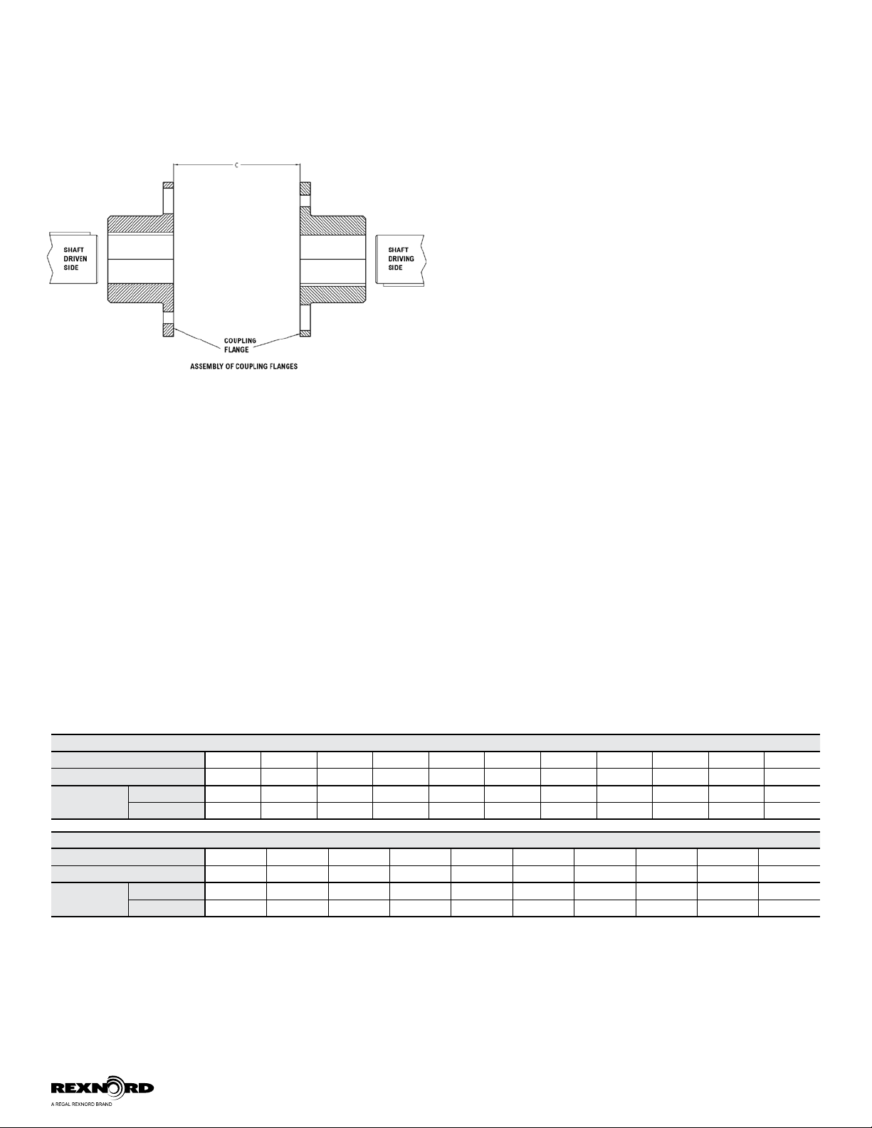
Note: 1. Refer to Rexnord®Bulletin 538-214 Coupling Alignment Fundamentals for more details regarding alignment methods and procedures.
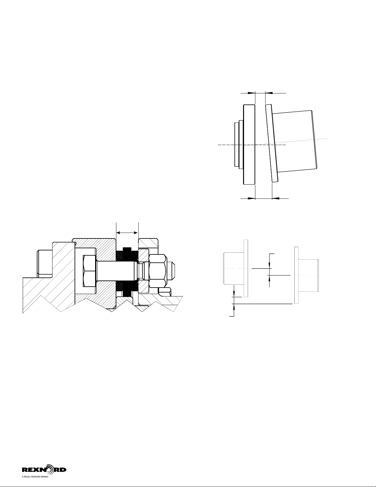
a. The Angular Misalignment value is the maximum difference between the measurements X and Y taken at opposite ends of the hub flanges, as shown in Figure 8.
b. The Parallel Misalignment value “P” is the offset between the centers of the hubs, as shown in Figure 9.