Introduction
CSE SOL G SRS1 T-E HDO Solar Pump Station is tted with a solar pump of the latest generation
that permits ow control either internally by selecting a suitable mode or externally through PWM
signal. The complicated setting of the right ow rate is not needed when the PWM signal is used, the
pump station keeps adjusting it automatically, depending on the actual solar radiation. This means
that the solar thermal system always works with the maximum possible eciency.
Thanks to a direct connection of the heating element into the special socket in the pump station, a
long power cable for the pump station and a cable ready to connect to a solar sensor, the installation
is easy and fast, no qualied electrician is needed.
2. Pump Station Description
Main Features
Application
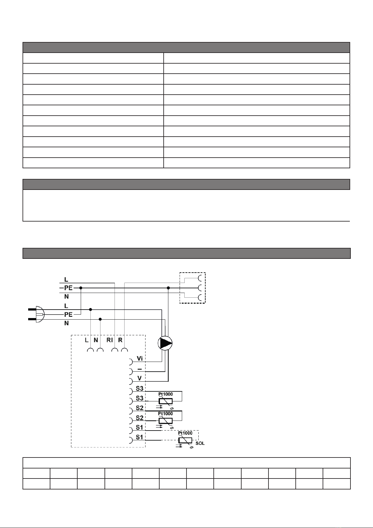
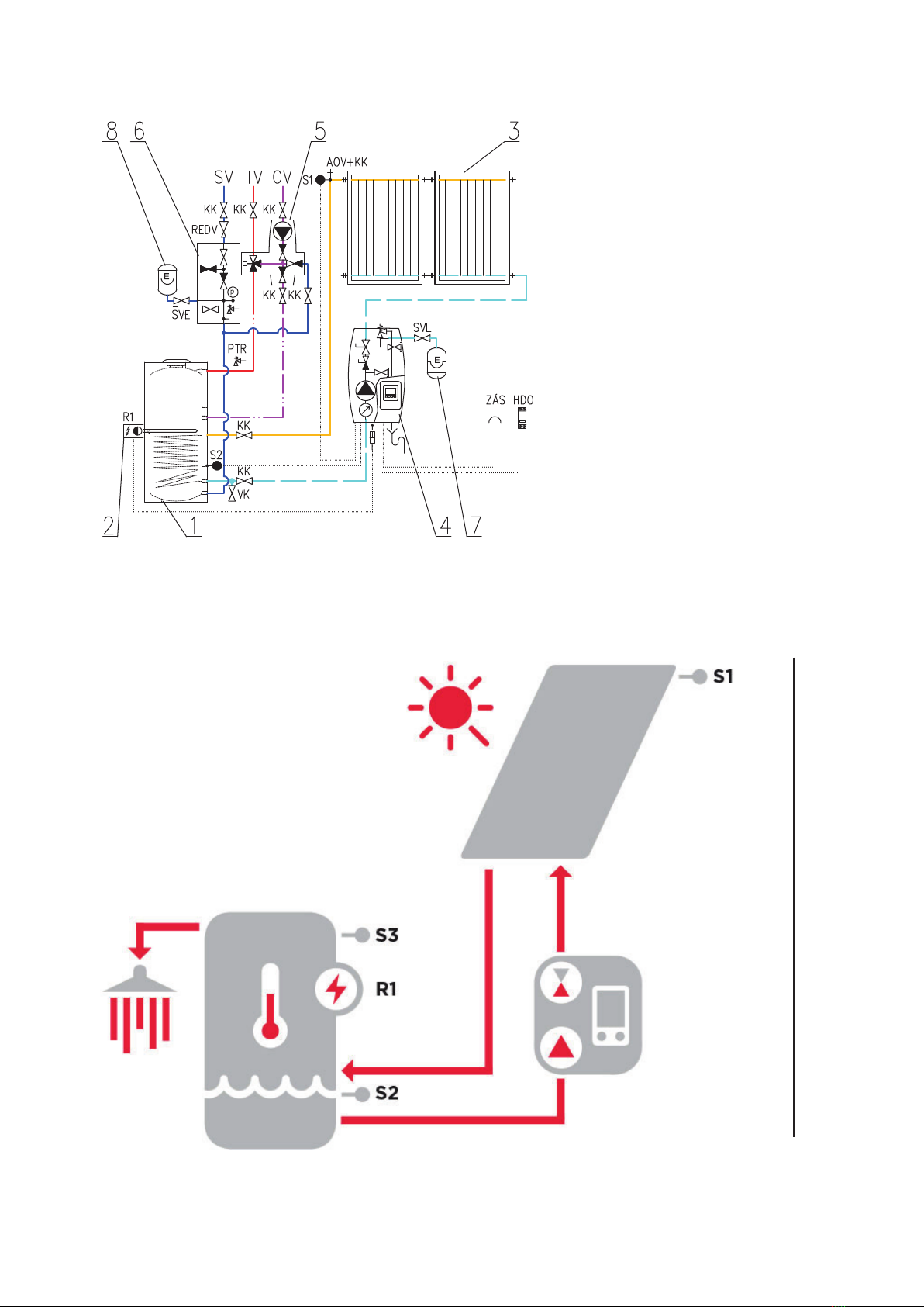
This solar pump station contains all components necessary for current and
ecient operation incl. complete electrical wiring. It is necessary to connect
only the collector temperature sensor and power cable for a heating ele-
ment via Ripple control contactor (see the following text).
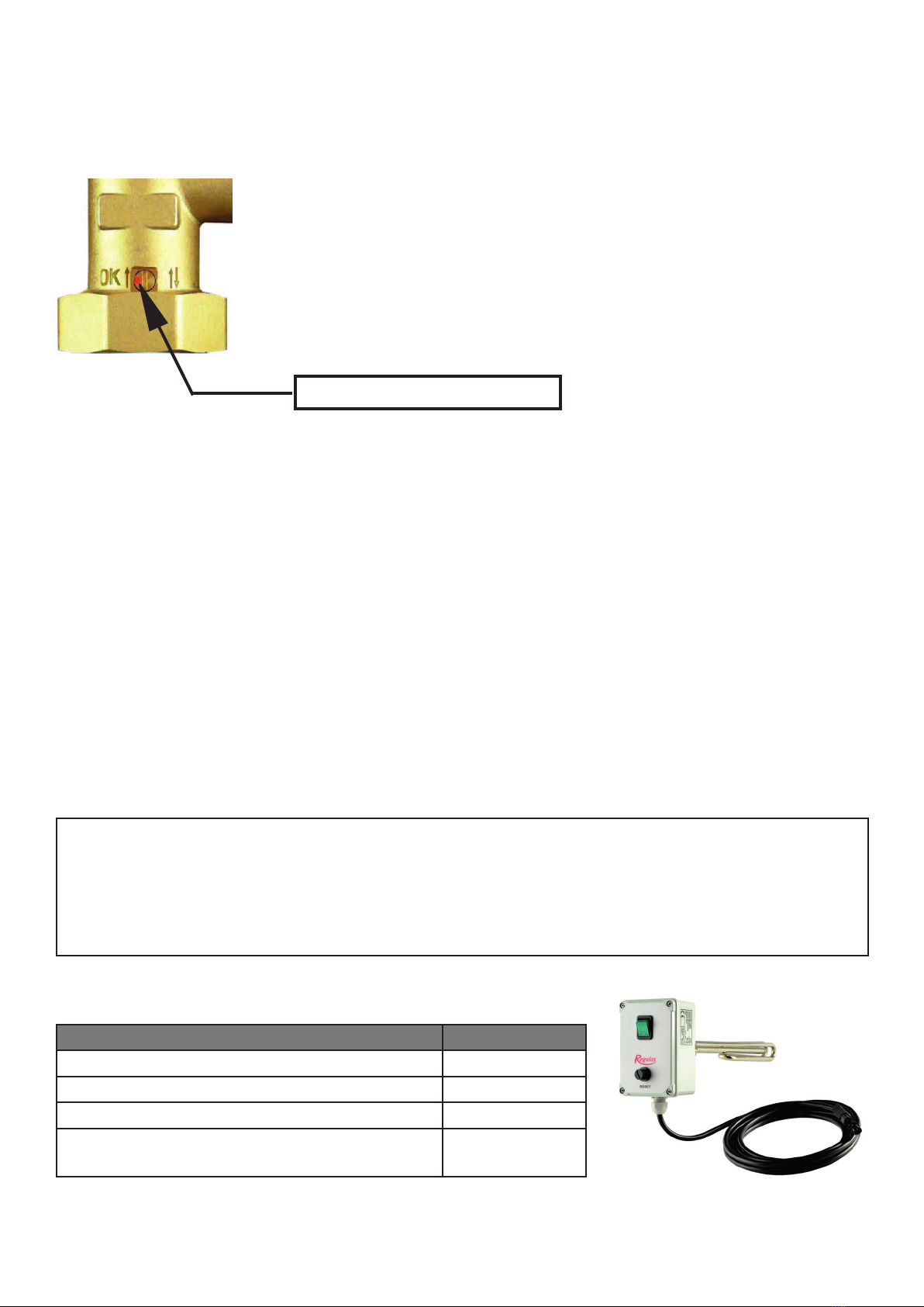
An electric heating element of up to 3 kW output can be connected to the
pump station. The pump station is equipped with a special socket for this
purpose.
The heating element is powered through a separate cable that is included
in the pump station. This cable connects to the power input switched by
Ripple control. The Ripple control contactor which blocks this input during
high tari periods shall be sized to exceed safely the power output of the
installed heating element.
Neither a heating element nor a Ripple control contactor are included in
supply.
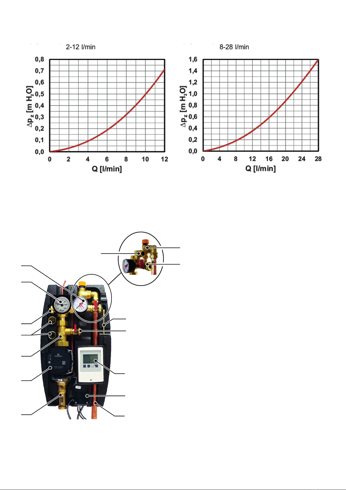
Description
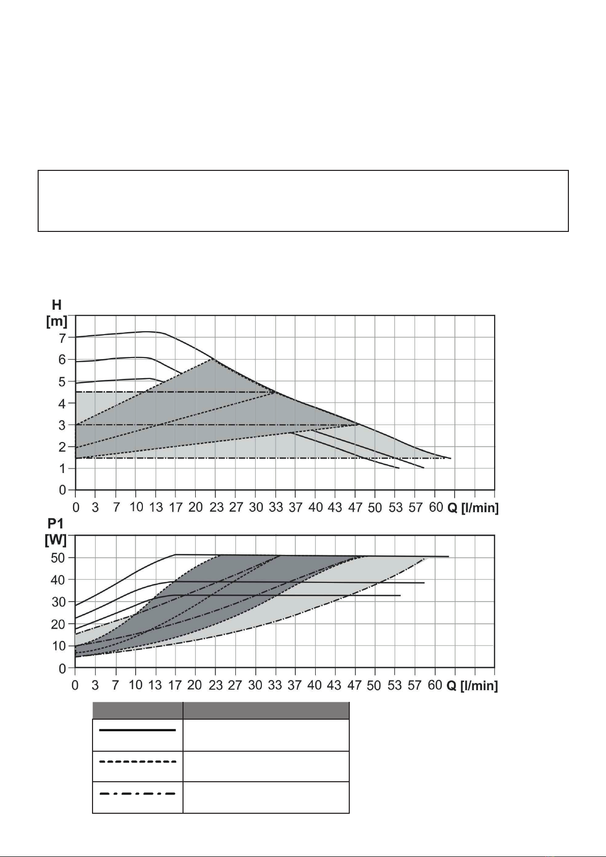
The pump station consist of a UPM3 Hybrid 25-70 pump, SRS1 T controller,
check and safety valves, 2 ball valves, pressure gauge, thermometer, el. wiring,
insulation and installation kit.
The pump station further involves:
● connection point for an expansion vessel
● safety valve outlet, incl. extension piping terminating under the pump station
for easier connection
● ball valves for lling, draining and topping up a solar thermal system
● special socket to connect a heating element of max. output of 3 KW / 230V
● two connected temperature sensors for solar consumer (4m cable)
● solar temperature sensor (2m cable, silicone insulation)
● cable for the power input switched by Ripple control (3m long, 3x1.5 mm2
cross section, black)
● 230V power cable w. el. plug (3m cable, PVC insulation)
Installation on a tank or wall
Working uid water-glycol mixture (max. 1:1)
Codes corresponding to connection sizes
Connection G 3/4“ M G 1“ M
Flow measurement range 2-12 l/min 8-28 l/min
Code 18968 18964