10 of 24 ISSUED:11-09-07 SHEET#:202-9252-1
Español
Visite el sitio Web de Peerless en www.peerlessmounts.com Para el Servicio al cliente llame al 1-800-729-0307 ó 708-865-8870
Contenido
Lista de piezas ........................................................................................................................................................................................ 11
Instalación en una pared con montantes de madera dobles .............................................................................................................. 12
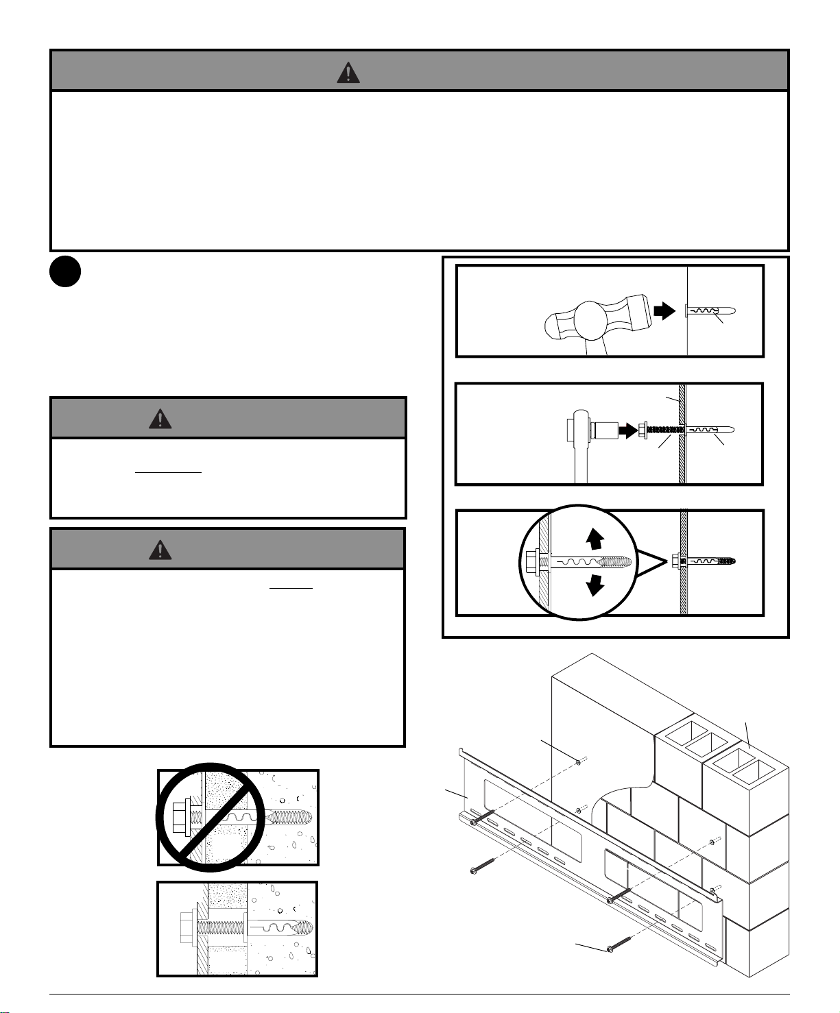
Instalación en una pared de concreto macizo o de bloques de hormigón de escorias .................................................................... 13
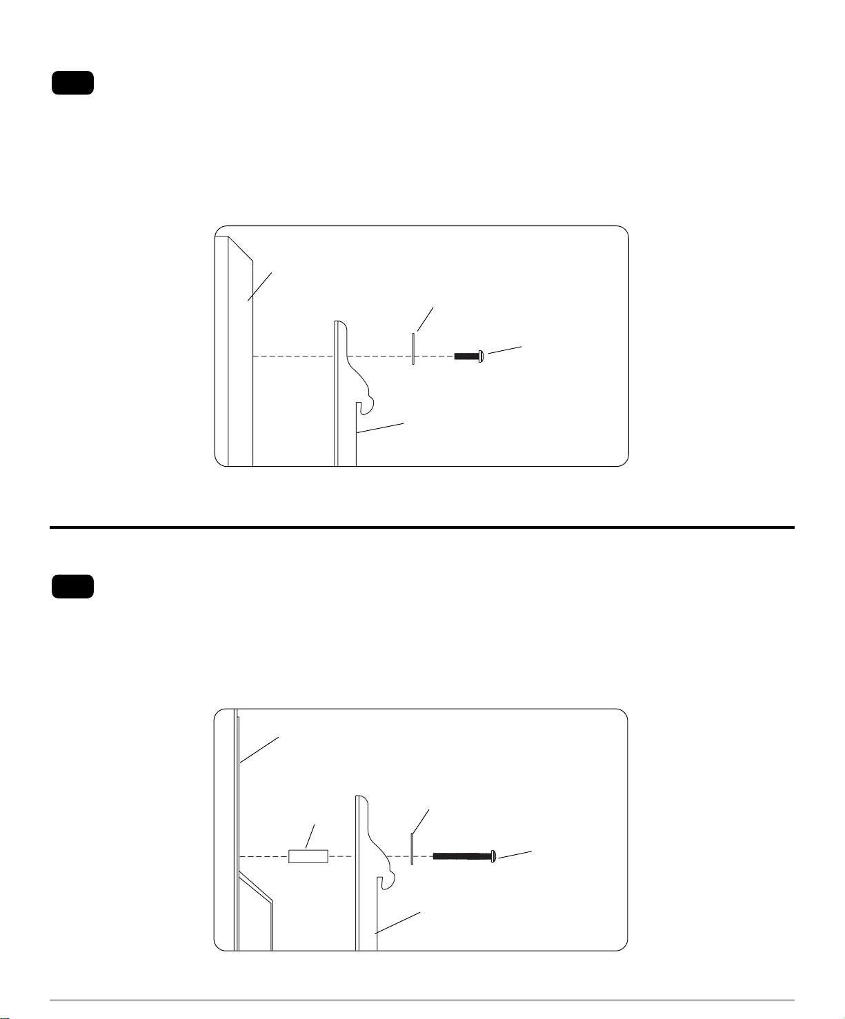
Instalación de los soportes adaptadores ............................................................................................................................................. 14
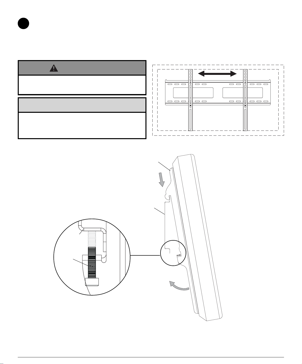
Instalación de la pantalla plana en la placa de apoyo ......................................................................................................................... 16
Para atención al cliente, llame al (800) 729-0307 ó (708) 865-8870.
Accessories
•Repisa ParamountTM - PCS200 para
componentes de A/V
•Juego de accesorios de piezas para la fijación en
montantes de metal - ACC415 (El montante de
metal no ha sido evaluado por UL)
Herramientas necesarias para el montaje
•localizador de montantes (se recomienda usar el de “borde a borde”)
•destornillador phillips
•taladro
•broca de 1/4" para pared de concreto y de bloques de hormigón de
escorias
•broca de 1/2" para pared con montantes de metal
•broca de 5/32" para pared con montantes de metal o madera
•nivel
• No comience a instalar su producto de Peerless hasta haber leído y entendido las instrucciones y las advertencias
contenidas en la Hoja de Instalación. Si tiene alguna pregunta acerca de cualquiera de las instrucciones o las
advertencias,porfavor,llameaServicio al ClientedePeerlessal1-800-865-2112.
• Esteproductosólodebeserinstaladoporunapersonaquetengauna aptitud mecánica, que tenga experiencia en
construcción básica de edificios y que entienda estas instrucciones en su totalidad.
• Asegúrese de que la superficie de apoyo sostendrá, con seguridad, la carga combinada del equipo y todos los
fijadoresycomponentes.
• Nuncasobrepaselacapacidad máxima desoportarcarga aceptada porUnderwritersLaboratories.(Vea lapágina9).
• Si va a instalar el producto en una pared con montantes de madera, asegúrese de que los tornillos de montaje estén
anclados en el centro de los montantes. Se recomienda utilizar un localizador de montantes de “borde a borde”.
• Siempre cuente con la ayuda de un asistente o utilice un equipo mecánico de izar para levantar y colocar el equipo
conmásseguridad.
• Apriete los tornillos con firmeza, pero no en exceso.Apretarlos en exceso puede dañar los artículos y puede
disminuirsignificativamentesufuerzade fijación.
• Este producto fue diseñado con la intención de que se instale en las superficies de apoyo marcadas abajo con los
accesorios de instalación incluidos en este producto como se especifica en la hoja de instalación. Para instalar este
productoenotrasuperficiedeapoyo,llame a Servicio al ClientedePeerlessal1-800-865-2112.
• Esteproductofuediseñadoparaserinstaladoenparedesconlasiguienteconstrucciónsolamente:
CONSTRUCCIÓNDELAPARED ACCESORIOSADICIONALES NECESARIOS
xMontantedemadera Ninguno
xVigademadera Ninguno
xConcretomacizo Ninguno
xBloquedehormigóndeescorias Ninguno
Montantedemetal No lo instale excepto con el juego de accesorios de Peerless para
montantes de metal.
Llame a Servicio al Cliente para pedir el juego de accesorios de
Peerless para montantes de metal.
Ladrillo ComuníqueseconServicioal Cliente.
¿Otrasuperficieonoestáseguro? Comuníquesecon Servicio alCliente.
ADVERTENCIA
Nota: Lea la hoja de instrucciones completa antes de comenzar la instalación y el ensamblaje.