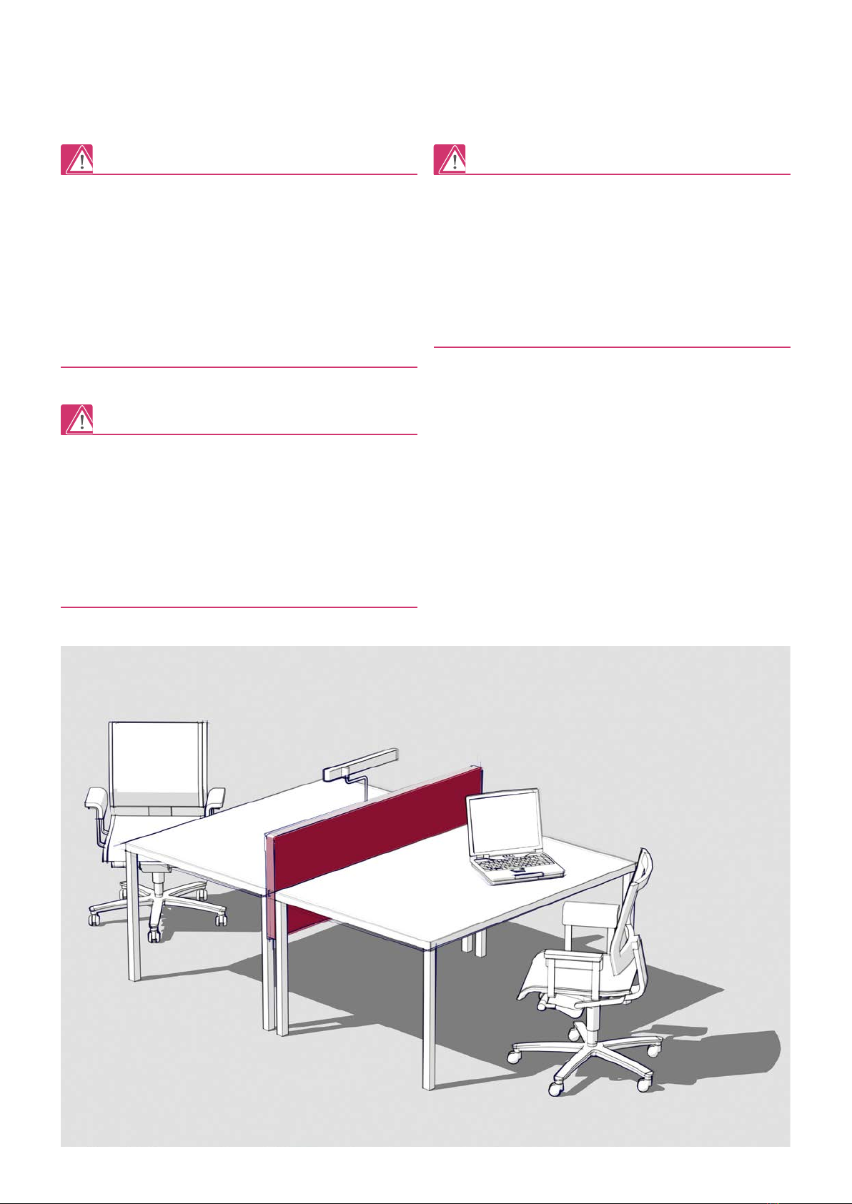
manuals.online logo
Brands
  1. Home
  2. •
  3. Brands
  4. •
  5. Rehau
  6. •
  7. Indoor Furnishing
  8. •
  9. Rehau Rauworks Fixed Screen User manual

Rehau Rauworks Fixed Screen User manual

Other Rehau Indoor Furnishing manuals

Rehau RAUWORKS FRONT B41604 User manual

Rehau

Rehau RAUWORKS FRONT B41604 User manual

Rehau RAUWORKS FRONT User manual

Rehau

Rehau RAUWORKS FRONT User manual

Rehau RAUVOLET VETRO-LINE User manual

Rehau

Rehau RAUVOLET VETRO-LINE User manual

Rehau FLIPDOOR User manual

Rehau

Rehau FLIPDOOR User manual

Rehau SKYFORCE Juliet Balcony Manual

Rehau

Rehau SKYFORCE Juliet Balcony Manual

Popular Indoor Furnishing manuals by other brands

Regency LWMS3015 Assembly instructions

Regency

Regency LWMS3015 Assembly instructions

Furniture of America CM7751C Assembly instructions

Furniture of America

Furniture of America CM7751C Assembly instructions

Safavieh Furniture Estella CNS5731 manual

Safavieh Furniture

Safavieh Furniture Estella CNS5731 manual

PLACES OF STYLE Ovalfuss Assembly instruction

PLACES OF STYLE

PLACES OF STYLE Ovalfuss Assembly instruction

Trasman 1138 Bo1 Assembly manual

Trasman

Trasman 1138 Bo1 Assembly manual

Costway JV10856 manual

Costway

Costway JV10856 manual

moss DESIGN Caisson Credenza Assembly instructions

moss DESIGN

moss DESIGN Caisson Credenza Assembly instructions

Aquaglide FULL DECK 15.0 owner's manual

Aquaglide

Aquaglide FULL DECK 15.0 owner's manual

AREBOS AR-HE-SW30 user manual

AREBOS

AREBOS AR-HE-SW30 user manual

Till-Hilft Fulda 87005.330 Assembly instructions

Till-Hilft

Till-Hilft Fulda 87005.330 Assembly instructions

Twoey Outside 2010 quick start guide

Twoey Outside

Twoey Outside 2010 quick start guide

Hettich Easys 200 operating instructions

Hettich

Hettich Easys 200 operating instructions

The bedboss RELAX 404 Series owner's manual

The bedboss

The bedboss RELAX 404 Series owner's manual

Oeseder Möbelindustrie Bern 991 720 Assembly instructions

Oeseder Möbelindustrie

Oeseder Möbelindustrie Bern 991 720 Assembly instructions

Costway HW68469 user manual

Costway

Costway HW68469 user manual

Next ALIX A27743 Assembly instructions

Next

Next ALIX A27743 Assembly instructions

BROSA Hans Assembly guide

BROSA

BROSA Hans Assembly guide

Prodigg MINIKA PBA015T-FUR installation manual

Prodigg

Prodigg MINIKA PBA015T-FUR installation manual

manuals.online logo
manuals.online logoBrands
  • About & Mission
  • Contact us
  • Privacy Policy
  • Terms and Conditions

Copyright 2025 Manuals.Online. All Rights Reserved.

Construction
Automotive
Industry
*Des solutions polymères à l’infini
From 01.05.2012
Subject to technical modifications
RAUWORKS FIXED SCREEN
DE MONTAGE-/ BEDIENUNGSANLEITUNG
EN ASSEMBLY / OPERATING INSTRUCTIONS
FR NOTICE DE MONTAGE / MODE D’EMPLOI
2
INHALT/CONTENT/CONTENU
Vorwort/Foreword/Avant-Propos . . . . . . . . . . . . . . . . .3
Hinweise/Information/Indications . . . . . . . . . . . . . . . . 4
Montage/Assembly/Montage. . . . . . . . . . . . . . . . . . .6
3
VORWORT/FOREWORD/AVANT-PROPOS
Sehr geehrte Kundin, sehr geehrter Kunde!
- Lesen Sie die Sicherheitshinweise und die Montage-/ Bedienungs-
anleitung zu Ihrer eigenen Sicherheit und zur Sicherheit anderer
Personen vor Montagebeginn aufmerksam und vollständig durch.
- Bewahren Sie die Montageanleitung auf und halten Sie diese zur
Verfügung.
- Falls Sie die Sicherheitshinweise oder die einzelnen Montage-/
Bedienungsvorschriften nicht verstanden haben oder diese für Sie
unklar sind, wenden Sie sich an Ihr REHAU Verkaufsbüro.
Dear customer!
- For your own safety and the safety of others, please read through all
safety warnings and assembly/operating instructions carefully and
completely prior to commencing assembly.
- Keep the assembly instructions safe and have them to hand.
- If you have not understood the safety instructions or the individual
assembly/operating guidelines or find them unclear, please contact
your REHAU sales oce.
Chère cliente, cher client !
- Veuillez, pour votre propre sécurité et celle d’autrui, lire attentive-
ment et intégralement cette notice / ce mode d’emploi avant de
procéder au montage.
- Veuillez conserver cette notice et la tenir à disposition.
- Veuillez vous adresser à votre agence REHAU en cas de diculté de
compréhension ou de manque de clarté des recommandations de
sécurité ou des diérentes prescriptions de montage / d’utilisation.
4
HINWEISE/INFORMATION/INDICATIONS
Allgemeine Sicherheitshinweise:
Nicht mehr benötigte Verpackungsmaterialien und Kleinteile von
Kindern fernhalten!
Nicht auf dieses Produkt stellen oder setzen. Im montierten Zustand
nicht anlehnen!
Der Tisch, an dem die Trennwand montiert wird, muss die Anforderun-
gen der DIN EN 527 erfüllen. Demnach muss der Tisch unter anderem
eine Abmessung von mindestens 1200 x 800 x 720mm (BxTxH)
haben und eine ausreichende Kippsicherheit gewährleisten.
Allgemeine Hinweise:
Montage durch zwei Personen empfohlen
(leichtere Handhabung)
Notwendige Hilfsmittel:
- 3 mm Innensechskant-Schlüssel
- Maßband oder Gliedermaßstab
Empfohlene Hilfsmittel:
- Gummihammer
- Kunststoplättchen
General safety information:
Keep discarded packaging material and small parts out of the reach of
children!
Do not stand or sit on this product. Do not lean on the screen in the
assembled condition!
The desk to which the screen is to be fitted must fulfil the require-
ments of DIN EN 527. According to this, amongst other things, the
desk must have dimensions of at least 1200 x 800 x 720mm (WxDxH)
and is to be suciently stable.
General information:
Assembly by two persons recommended
(easier to handle)
Required tools:
- 3 mm hexagon socket wrench
- Measuring tape or folding rule
Recommended tools:
- Rubber hammer
- Plastic plate
Consignes générales de sécurité :
Mettre le matériel d’emballage qui ne sert plus et les petites pièces
hors de portée des enfants !
Ne pas monter ou s’assoir sur ce produit. Ne pas s’adosser au produit
monté !
Le bureau recevant la cloison doit répondre aux exigences de la norme
DIN EN 527. Celui-ci aura entre autres les dimensions minimales de
1200 x 800 x 720mm (l x p x h) et devra disposer d’une stabilité
susante contre le basculement.
Indications générales :
Nous recommandons un montage par deux
personnes (simplifie la manutention)
Matériel indispensable :
- Clé Allen de 3 mm
- Mètre ruban ou mètre pliant
Matériel recommandé :
- Maillet caoutchouc
- Plaques en plastique
5
Teileliste/Parts list/Nomenclature des pièces :
Screen:
Pos./Item/Rep. A B C D E
Menge/
Quantity/
Quantité
1x 1 Paar/
1 pair/
1 paire
2x 4x 4x
Maße (mm)/
Dimensions
(mm)
B x 800 x 55 130 x 80 x 70 80 x 20 x 12,5 D5 x 16 10 x 8 x 7,5
Abbildung/
Image
Organisationsschiene (Set)*/Organisation rail (set)*/Support d’accessoires (set)* :
Pos./Item/Rep. F C D E
Menge/
Quantity/
Quantité
1x 2x 4x 4x
Maße (mm)/
Dimensions
(mm)
B x 80 x 16 80 x 20 x 12,5 D5 x 16 10 x 8 x 7,5
Abbildung/
Image
Zubehör*/Accessories*/Accessoires* :
Pos./Item/Rep. G H J
Menge/
Quantity/
Quantité
1x 1X 1X
Maße (mm)/
Dimensions
(mm)
395 x 280 x 62 272 x 350 x 62 388 x 166 x 95
Abbildung/
Image
Bitte prüfen Sie vor Beginn der Montage, ob alle Einzelteile vorhanden sind.
*Nicht standardmäßig im Lieferumfang enthalten; liegt nur bei separater Bestellung bei.
Please check prior to starting assembly that all of the individual parts are available.
*Not included as standard in the scope of delivery; only supplied if ordered separately.
Veuillez vérifier la disponibilité de toutes les pièces avant de commencer le montage.
*Non inclus dans la prestation standard, fourni uniquement sur commande spécifique.
6
MONTAGE/ASSEMBLY/MONTAGE
1A E
A
E
E
Vertikales Rahmenprofil
Vertical frame profile
Montant vertical
mind. 55 mm
60
mm
RAUWORKS fixed screen Zusammenbau,
Geometrie aus REHAU-Zeichnung
PKS-15210 A vom 29.02.2012 ,
jedoch mit vereinfacht dargestellter Stoffbespannung ;
Positionierung der Nutensteine
für Einbauanleitung.
M1:2
15.05.12 Fa. REHAU AG+Co,
Konstruktion CCT-IS,
Kiessling 2424
≥ 55 mm 60 mm
7
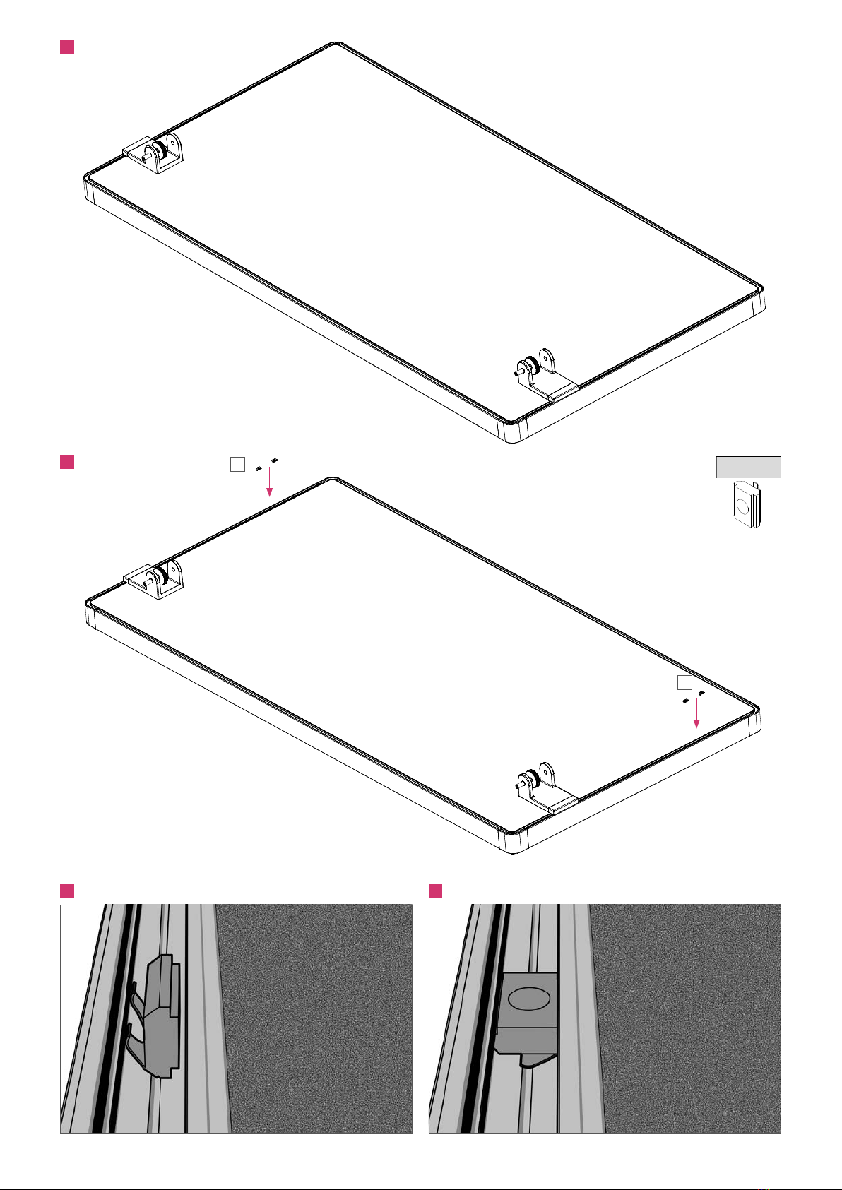
Positionierung der Nutensteine im vertikalen Rahmenprofil
Unbedingt auf festen und korrekten Sitz der Nutensteine achten, da
sonst der erforderliche Halt der Trennwand am Tisch nicht gewähr-
leistet ist.
Querschnittsdarstellung der Montage des Nutensteins ins
Rahmenprofil
a. Zur Montage der Nutensteine den Screen (A) flach auf eine
saubere und ebene Unterlage legen.
b. Die Nutensteine (E) sind, um Ihnen die Montage zu erleichtern,
bereits im Auslieferungszustand in das vertikale Rahmenprofil
eingesetzt. Beim Transport kann sich deren Position jedoch
verändern. Achten Sie deshalb bitte darauf, dass die Nutensteine
mit einem Mindestabstand von 55mm zur Oberkante des
Rahmens und einem Achsabstand von 60mm positioniert sind.
Um eine schiefe Positionierung am Tisch zu vermeiden, ist auf
beiden Seiten der Tischtrennwand auf gleichen Abstand zur Ecke
des vertikalen Rahmenprofils zu achten.
c. Wiederholung von Schritt b für das zweite Nutensteinpaar in dem
gegenüberliegenden vertikalen Rahmenprofil.
1
Positioning of the bolts for T-grooves in the vertical frame
profile
It is to be ensured without fail that the bolts for T-grooves are located
securely and correctly, otherwise the necessary stability of the screen
on the desk cannot be guaranteed.
a. To insert the bolts for T-grooves, lay the screen (A) flat on a clean,
even surface.
b. The bolts for T-grooves (E), to make it easier for you to insert
them, are already positioned in the vertical frame profile in the
supply condition. Their position can however change during
transport. Please therefore ensure, that the bolts for T-grooves are
positioned with a minimum gap from the pre-position of the bolts
for T-grooves, with a minimum gap at the side of 55 mm from the
top edge of the desk attachment, and a gap from the centre of 60
mm. In order to avoid slanted positioning on the desk, it is to be
ensured that both sides of the screen are the same distance from
the corner joints of the vertical frame profile.
c. Repeat from step b for the second pair of bolts for T-grooves in the
opposite vertical frame profile.
1
Positionnement des coulisseaux dans la rainure du montant
vertical
Veillez impérativement à ce que les coulisseaux soient bien fixés à leur
emplacement, faute de quoi la cohésion de la cloison avec le bureau
ne peut être assurée.
a. Posez la cloison (A) sur une surface propre et plane afin de monter
les coulisseaux.
b. Pour vous faciliter le montage, les coulisseaux (E) sont livrés
pré-insérés dans le montant vertical. Ils peuvent cependant se
déplacer au cours du transport. Vérifiez par conséquent que les
coulisseaux soient dans leur position initiale, à savoir à 55 mm au
minimum du bord supérieur du cadre (extérieur) et respectent un
entraxe de 60 mm. Veillez à ce que de chaque côté il y ait une
distance égale par rapport à la pièce d’angle du montant pour
éviter une pose inclinée de la cloison.
c. Répétez l’étape b pour la deuxième paire de coulisseaux dans le
montant opposé.
1
8
=
=
B D
C
C
C
B
D
B
D
2
3
Stellschraube
Adjusting screw
Molette de réglage
9
a. Tischanbindung (B) auf vorpositionierte Nutensteine aufsetzen.
b. Die Stellschraube muss an der jeweiligen Tischanbindung nach
unten zeigen.
c. Schrauben (D) in Nutensteine mit 3 mm Innensechskantschlüssel
einschrauben.
d. Schrauben (D) festziehen (siehe Warnhinweis!).
Das empfohlene Anzugsmoment mit Drehmomentschlüssel
beträgt 2 ± 0,5 Nm.
e. Führen Sie die Schritte a bis d für die Befestigung der zweite
Tischanbindung durch.
Anschrauben und Positionieren der Tischanbindungen
a. Abdeckkappen (C) auf Tischanbindungen aufstecken.
Mit Hilfe eines kleinen Gummihammers kann die Montage der Abdeck-
kappen erleichtert werden. Bitte vorsichtig und gleichmäßig aufbringen.
Aufstecken der Abdeckkappen auf die Tischanbindungen
Auf festen Sitz der Schrauben und Nutensteine achten! Bei Nichtbe-
achtung besteht die Gefahr, dass die Tischanbindung nicht hinrei-
chend mit dem Trennwandelement verbunden ist. Als Konsequenz
droht ein Herunterfallen der Trennwand mit Verletzungsgefahr.
3
2
a. Ax the desk attachment (B) to the pre-positioned bolts for
T-grooves.
b. The adjusting screw must point downwards on the respective desk
attachment.
c. Screw the screws (D) into the bolts for T-grooves with a 3 mm
hexagon socket wrench.
d. Tighten the screws (D) (see warning!).
e. The recommended tightening torque with the torque wrench is
2 ± 0.5 Nm.
f. Repeat steps a to d to ax the second desk attachment.
Screwing in and positioning the desk attachments
a. Push the cover caps (C) onto the desk attachments.
The assembly of the cover caps can be made easier with the help of a
rubber hammer. Please attach carefully and evenly.
Pushing the cover caps onto the desk attachments
Ensure that the screws and bolts for T-grooves are located securely! If
this is not done, there is a risk that the desk attachment will not be
attached securely enough to the screen element. As a consequence,
there is a risk that the screen will fall o and cause injury.
3
2
a. Placez les fixations (B) sur les coulisseaux en place.
b. La vis de réglage de chaque fixation doit être dirigée vers le bas.
c. Vissez les boulons (D) dans les coulisseaux à l’aide d’une clé Allen
de 3 mm.
d. Serrez fermement les boulons (D) (cf. avertissements !).
e. Le couple de serrage à la clé dynamométrique est préconisé
à 2 ± 0,5 Nm.
f. Suivez les étapes a à d pour la fixation de la deuxième fixation.
Vissage et positionnement des fixations
a. Emboîtez les caches (C) sur les fixations.
Pour faciliter le montage des caches, vous pouvez utiliser un maillet
caoutchouc. L’emboîtement des caches est à eectuer avec précaution
et de manière identique à gauche et à droite.
Emboîtement des caches sur les fixations
Veillez à ce que les boulons et coulisseaux soient bien fixés ! A défaut,
la fixation risque de ne pas être susamment solidaire de la cloison
entraînant un risque de chute de la cloison et de blessure le cas
échéant.
3
2
10
E
E
E
4
5
5.1 5.2