Rehau SKYFORCE Juliet Balcony Manual

SKYFORCE
Juliet Balcony
Technical Information
Windows. Reinvented for modern life.
Find out more at rehau.uk/skyforce

Contents
SKYFORCE Juliet balcony
01 General and safety information 3
02 System description 4
03 Profile print
03.01 SKYFORCE frame sets 5
03.02 SKYFORCE installation screw 6
03.03 SKYFORCE glass edge protector 6
03.04 Gasket insertion tool 6
04 Fall protection explained 7
04.01 Term definition 7
04.02 Proof of stability 7
04.03 Juliet balcony as fall protection 8
04.04 Fasteners 8
04.05 Fastening examples 8
05 Detail drawings 9
05.01 General information 9
05.02 Horizontal deductions 9
05.03 Vertical deductions 10
05.04 Fastening overview - GENEO 11
05.04.01 Remarks - GENEO 11
05.05 Fastening overview - TOTAL70 12
05.05.01 Remarks - TOTAL70 12
05.06 Installation example - TOTAL70 13
06 Fabrication 14
06.01 Transport and storage of aluminium profiles 14
06.02 Processing 14
06.03 Installation 14
06.04 Cleaning 15
06.05 Coating of aluminium 15
06.06 Cutting the mounting profile 15
06.07 Cutting down standard sets 15
06.08 Drill pattern for screws 16
07 Statics 20
07.01 Determination of loads 20
07.02 Required building regulations: 20
07.03 Barrier load 21
07.04 Glass type 21
07.05 How to read the spreadsheets 22
08 Static tables 24
08.01 Approved reinforcement 24
09 Glass tables 25
10 Notes 29
2

Validity
This information is valid globally.
Check for the latest version
For safety and the correct use of our products, please
check the latest version of our technical information.
To get information on the latest version please contact
REHAU or visit www.REHAU.com/ti.
Navigation
At the beginning of this manual you will find a detailed
table of contents with titles to the related pages.
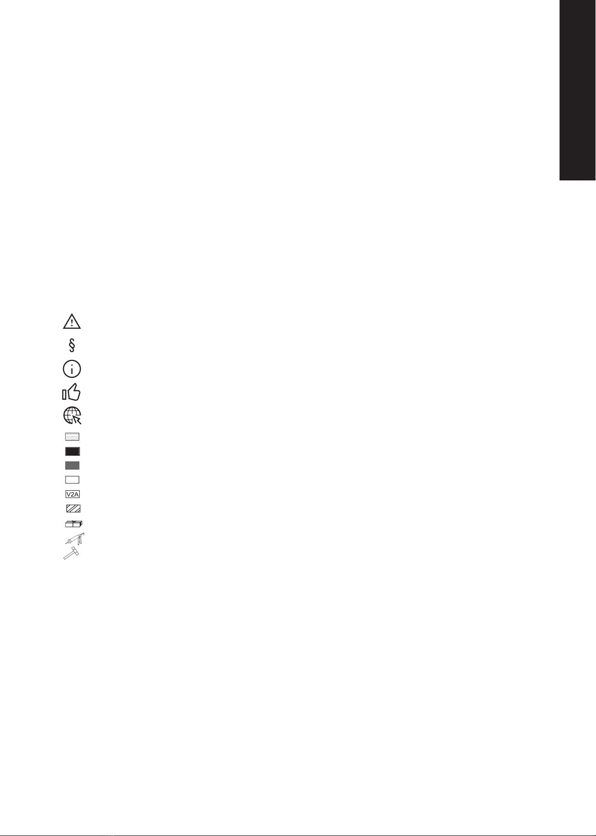
Pictograms and logos
Safety information
Legal information
Important information
Benefits
Information online
Colour varies
Colour black
Colour grey
Colour white
Stainless steel
Anodised aluminium
Package quantities
Seal with silicone
Soft face mallet (non-rebound)
Distribution of information
Please make sure that your customers (e.g. end
consumers) are informed about the correct use and
maintenance of this product. The use and maintenance
information needs to be made available to the end
consumer by you or your customer.
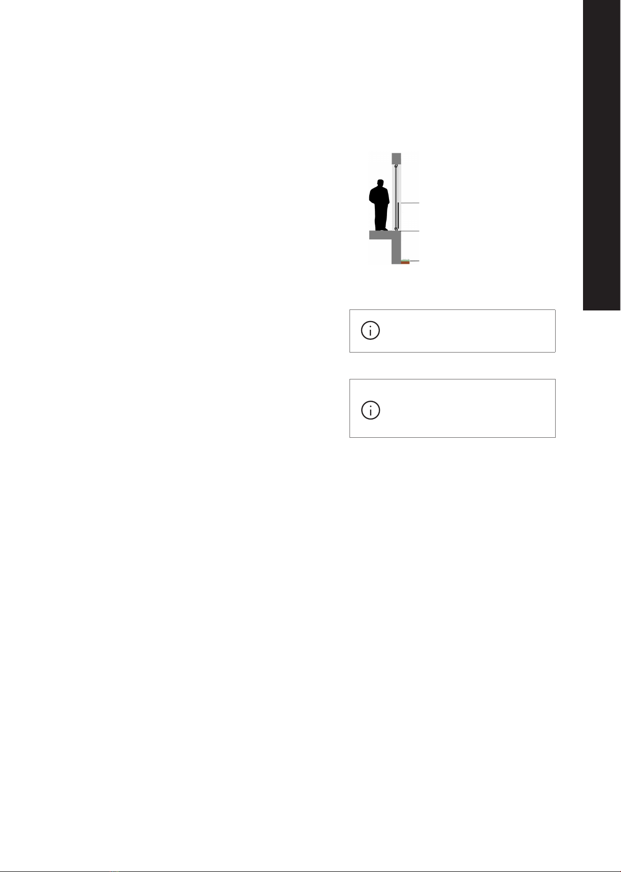
Correct application
The SKYFORCE Juliet balcony system can only be
specified, fabricated and installed as directed in this
technical documentation. Any deviation is prohibited.
Suitability of materials
The current technical documentation needs to be
followed for fabrication, installation and use of
SKYFORCE. Our technical documentation is based on
testing and experience at the time of print. The transfer
of this document does not entail any warranty of
properties for the listed products. No warranty can be
derived from this document. The information contained
within this document does not exonerate any user/buyer
from checking the suitability of the product for the
specific application in question.
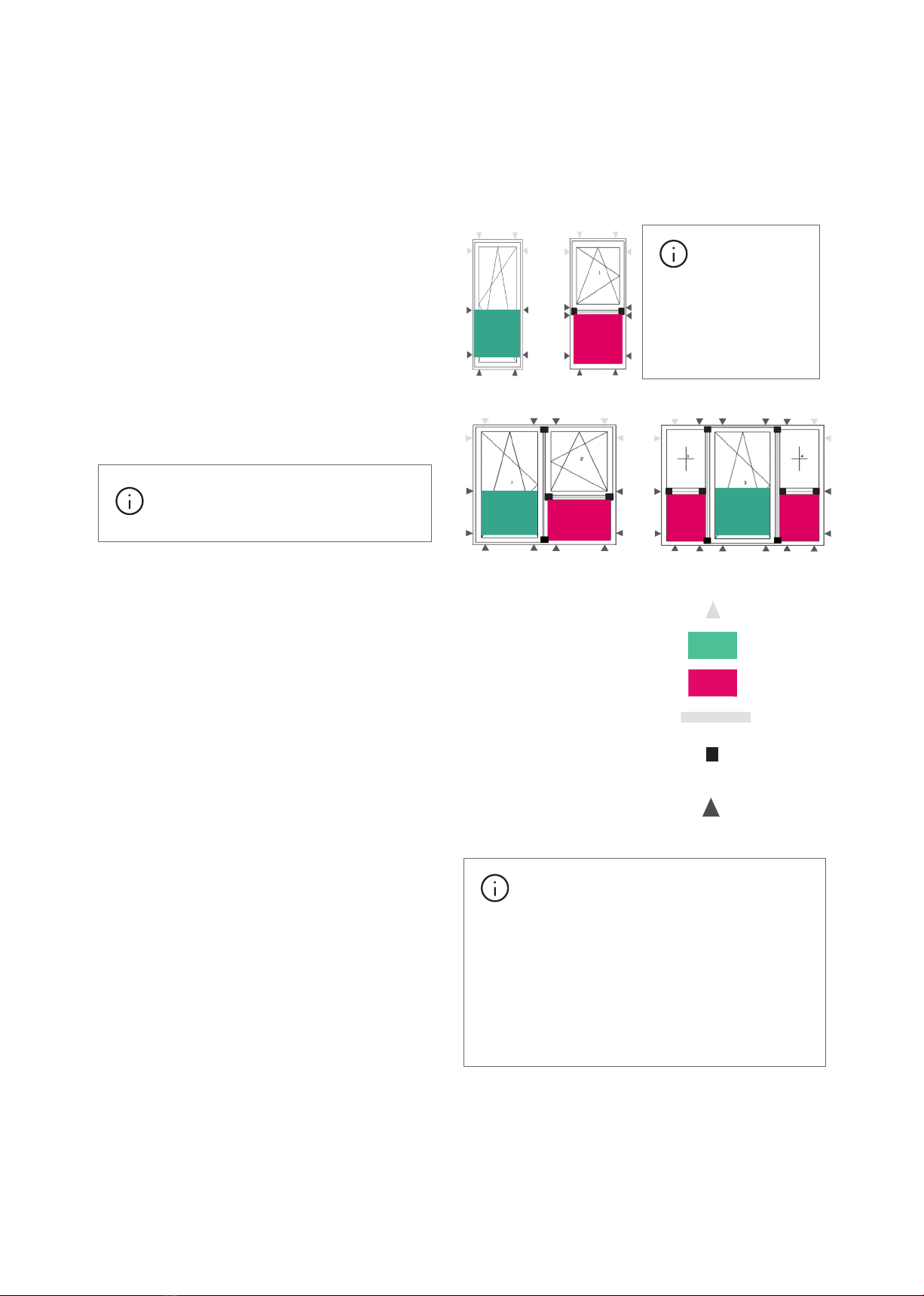
Maintenance and care
In order to ensure the functionality of SKYFORCE over
an extended period of time it is necessary to maintain it
regularly. SKYFORCE is also used as fall protection,
because of this all components need to be kept in proper
condition. Any occurring damages need to be assessed
by the installation company or the fabricator and
replaced if necessary.
Therefore the following maintenance should be carried
out at least once a year:
• Check whether there are visible or noticeable
damages to any of the gaskets, profiles, windows or
fasteners of the french balcony or window.
• If there is damage to the glass, a replacement is
necessary.
• Check the surface and clean if necessary.
For these reasons REHAU recommends to share this
information about maintenance and care with the end
consumer.
01 General and safety information
3
Information / Safety Instructions

Disclaimer
This product has been manufactured by Onlevel
GmbH. REHAU Ltd has no liability for any injury or
damage to the property as a result of product or
installation failures.
The system of invisibility
SKYFORCE oers an innovative fall protection solution
for french balconies. Not only is it one of the first
nearly invisible system solutions, but it is one of the
best systems on the market due to its quick and easy
installation.
The installation only requires the use of standard tools
as the inimitable slide and clip technology allows direct
fastening to the window profile. The best feature is
that only one profile is needed to cover all glass
options (length, width and thickness).
Benefits at a glance:
• Complete pre-assembled sets of 1000mm height.
Glass thickness 12.76 mm or 21.52 mm
• Other options available as sets or extrusion
lengths upon request
• New, visually appealing state of the art system
with closed design
• Quick and easy installation
• Concealed fastening system (closed system, all
visible parts in the same colour)
• The following surface finishes are available in
stock:
• Mill finish
• Anodised aluminium E6/C0(EV1)
• RAL 7016 anthracite grey
• RAL 9016 white
• Further surface finishes available on request.
02 System description
4

-Part complete set of jamb rails incl. gaskets, without glass
Glass thickness
mm
Glass height
mm
Surface finish Article number
. Mill finish -
. 1000 Anodised aluminium E6/C0(EV1) -
. 1000 RAL anthracite grey -
. 1000 RAL white -
. 1000 Mill Finish -
. 1000 Anodised aluminium E6/C0(EV1) -
. 1000 RAL anthracite grey -
. 1000 RAL white -
03 Profile print
50
37
Please remember the glass edge protectors
and fasteners when ordering
The profile lengths for the set is
glass height + mm = mm
03.01 SKYFORCE frame sets
Table 1: Frame set overview
Fig. 1: SKYFORCE frame set
5
Information / Safety Instructions

Installation screw
Ø . stainless steel VA
Length
mm
Ø. x mm installation screw, matched to the
recommended profiles
System Article number
bag GENEO, TOTAL -
Glass edge protector including glass mounting tape
Width
mm
Glass thickness
mm
Length
mm
Surface finish Article number
.
Anodised aluminium E/C(EV)
-
.
Anodised aluminium E/C(EV)
-
.
Anodised aluminium E/C(EV)
-
Description
Artice number
Gasket insertion tool
-
03.02 SKYFORCE installation screw
03.03 SKYFORCE glass edge protector
03.04 Gasket insertion tool
Table 2: Installation screw overview
Table 3: Glass protector overview
1
Table 4: Gasket insertion tool overview
Fig. 2: Installation screw
Fig. 3: Glass edge protector
Fig. 4: Gasket insertion tool
12 x screws per bag
1
6

04 Fall protection explained
04.01 Term definition
Many countries have fall protection requirements for heights of
0.5 - 1 m. For the meaning of barrier height and fall height see
Fig. 5.
04.02 Proof of stability
Fall protection window units need to be approved by a structural
engineer. Fall protection is a property of the window unit as a
whole. This includes glazing, the profile system, mullion or
transom and their connections including the fastening of the unit
to the building structure. For the connections the characteristic
load-bearing capacity FRk of the T-connection is essential. The
verification for the connectors can be found in VI from 1.10.2018
"Absturzsicherheit - Verbinder für absturzsichernde Fenster".
From a fall height of 0.5 - 1 m or 1.1 m the window needs to
adhere to the fall protection guidelines. This includes a window
mounted juliet balcony. This means a structural engineer needs
to make sure that the complete unit and its installation is
structurally sound and fit for purpose. All critical parts must be
coordinated with each other and must follow the local and
country specific rules and regulations.
Fig. 5: Term definition
Barrier height
Fall Height
A juliet balcony for fall protection falls
under the term barrier.
A structural engineer must check the
complete installed window unit is
structurally sound and fit for purpose
7
Fall Protection

Standard fastening point
Juliet balcony
Fall protection glazing
Unsupported member
Mullion connection
Fall protection fastening point.
Proper shimming of the installation
gap is required.
Because of a danger to life and limb with fall
protection applications the following things need
to be available in order to be safe:
- Test certificates for all components
- A structural engineering certificate for the individual
project
- A compliance certificate for the end consumer / home
owner in addition to the above it needs to be verified
that only approved REHAU window systems are used
with SKYFORCE.
04.03 Juliet balcony as fall protection
The glass for SKYFORCE is categorised as fall protection
according to DIN 18008 Part 4, Cat. A. This is with glass
edge protection on top and without glass edge protection
connected on either side. The glass balcony consists of
double-sided linearly mounted glass, held in place by an
aluminium profile with EPDM gaskets on either side.
SKYFORCE has been tested by the German Institute for
Construction Engineering in Berlin, AbP Nr. VT 17-083.1P.
The juliet balcony system is delivered without glass. Please
see table 11 to find the correct glass for your application.
Glass can be ordered directly at a glass supplier of choice.
04.04 Fasteners
The fastening of the window or door unit to the building can
be done using appropriate fasteners. The load transfer from
the juliet balcony through the window/door unit into the
building framework needs to be proven. Fasteners oering
such proof are available from:
- Fa. Würth
- SFS intec
- Illbuck
- Innoperform
- Ejot
Heed the advice of the respective supplier.
04.05 Fastening examples
The maximum distance between fastening points is 700
mm, the distance from the inner corner of the profiles is
150mm. See also - installation guidelines. The units
displayed need to be checked for suitability forthe use as
fall protection by a structural engineer.
In case a mullion
is used the
connection needs to be
checked by a structural
engineer. Welded in
mullions are not suitable
for this application.
The proper fastening of a window or door
with fall protection needs to be checked by a
structural engineer.
8

Single units
Glass = EW - 30 - 2x
Glass edge protector = Glass - 32
Element width (EW)
Fastener axis (FA) = EW -2 X
Balcony width (BW) FA + 40
X
X according to detail drawings.
See page 11-12.
SKYFORCE must not protrude
past the flat frame body
Glass dimensional tolerance:
Horizontal: width tolerance +4/0 mm
Vertical: height tolerance +3/0 mm.
Screw must not drill through
reinforcement fold
X
X
Legend
Glass (Glass width) EM - - X
FA (Fastener axis) EM - X
BW (Balcony width) EM - X +
EW (Element width) -
X(Finished aperture +
SKYFORCE cap Install) (Min. ) +
Table 5: Horizontal deduction equations
05 Detail drawings
05.01 General information
05.02 Horizontal deductions
9
Detail Drawings

Barrier height
OH
PL
*y
Glass
The frame top edge is the reference
point for the barrier height.
* In case the distance "Y" between the frame
top edge and glass bottom edge is greater than
30mm an additional glass edge protector needs
to be used for the bottom glass edge.
Vertical deductions
Glass
(Glass height)
PL
(Profile length)
Glass + mm
OH
(Overall height)
Glass +
Y
(Distance frame - glass)
Barrier height - PL - mm
Table 6: Vertical deduction equations
05.03 Vertical deductions
10

Frame 72 Frame 86
• The SKYFORCE elements need to be positioned in a way that
allows for the entire aluminium section to sit flush on the
frame profile.
• The possible screw positioning range is shown below
• Fastening screw Ø 6.3 x 64 mm, 821196-001.
18-28 (X) 18-32 (X)
Mullion 98
• Pre-drill for steel reinforcement thickness:
• 1.5 mm with Ø 5 mm,
• 2-5 mm with Ø 5.3 mm
• 6 mm with Ø 5.5 mm
• 7-10 mm with Ø 5.7 mm.
• There is no need to open up the PVC with a larger
drill.
45-53 (X)
Unsuitable for use with SKYFORCE
Reason
GENEO without reinforcement
Insuicient static fastening
05.04.01 Remarks GENEO
Table 7: GENEO remarks
05.04 Fastening overview GENEO
11
Detail Drawings

Frame 72mm 3-Chamber Frame 72mm 5-Chamber
20-29 (X) 20-29 (X)
• Pre-drill for steel reinforcement thickness:
• 1.5 mm with Ø 5 mm
• 2-5 mm with Ø 5.3 mm
• 6 mm with Ø 5.5 mm
• 7-10 mm with Ø 5.7 mm.
• There is no need to open up the PVC with a larger
drill.
• The SKYFORCE elements need to be positioned in a way that
allows for the entire aluminium section to sit flush on the
frame profile.
• The possible screw positioning range is shown below
• Fastening screw Ø 6.3 x 64 mm, 821196-001.
Suitable for use with SKYFORCE
mm - chamber
Reinforcement: (.mm)
mm - chamber
Reinforcements: (.mm) (mm)
Unsuitable for use with SKYFORCE
Reason
T mullion
No mechanical joint option. T mullion needs to be mechanically jointed
05.05.01 Remarks TOTAL70
Table 8: TOTAL70 remarks
05.05 Fastening overview TOTAL70
12

The installation of SKYFORCE happens after all
building envelope works have been finished. A
minimum distance of 5 mm between the finished aperture
and the SKYFORCE are needed to install the aluminium
cap. The glass installation is done from the exterior, make
use of scaolding where needed. The combined weight of
glass and installer need to be considered to choose
suitable scaolding.
05.06 Installation example - TOTAL70
13
Detail Drawings

06.01 Transport and storage of aluminium profiles
The SKYFORCE sets are packed into cardboard boxes and
therefore suiciently protected against mechanical influence.
Mill finished extrusion lengths of aluminium need special
attention in regards to transport and storage. Although
transport, handling or storage issues are of little influence to
the function of the aluminium profiles they will show negative
eect after the surface finish has been applied. Possible
issues are water spots, corrosion, scratches, rub marks, dents
or bends.
Storage must not allow the profiles to be dented, scratched or
bent. Therefore please make sure to use support material
made of soft material such as (untreated) timber or plastic.
Under no circumstance should the profiles stand on concrete
flooring or get in contact with brickwork, plaster, steel or
other metals.
Mill finish extrusion length aluminium profiles are to be kept
safe from moisture. Therefore:
• Unpack them immediately after receipt, use gloves to
prevent the transfer of any moisture or finger prints onto
the material.
• Avoid direct contact between the profile and water.
• Pay attention to putting "cold" profile in storage as it
might build condensation.
• Use a soft cloth to wipe down any wet profile.
• No unprotected storage of aluminium profile outside,
keep them inside and free of dust. Keep dry and
ventilated in a room with relatively low humidity.
• Assure good ventilation of the storage facility and replace
wet paper inter layers with dry ones.
• Aluminium profiles should not be stored for extended
periods of time, they should be used as soon as possible
due to the potential of corrosion over time.
• If stored over longer periods of time they should be
sprayed with corrosion protection.
06.02 Processing
In order to get the best possible result when cutting the
profile it is recommended to use a saw with adjustable cutting
and blade speed. Generally the correct cutting angle and
proper spanning of the profile needs to be observed. In order
to avoid pressure points and or scratches it is recommended
to assure clean contact surfaces of machinery and profile. The
profile surface should be protected using protective film.
We recommend the following saw blade:
• Blade type: HM
• Diameter: 300 - 400 mm
• Tooth shape: Trapezoid-flat, negative
• Tooth pitch: Fine
• RPM: 3000 - 4000 min-1
• Cutting speed: 50 - 60 m/s
Please adjust the cutting speed in a way that allows the cut
material to be transported away to avoid deformation of the
profile. Suitable coolant and/or lubricant is recommended.
The sharpness of the blade is essential because a dull blade
could create too much heat and collect melted material
between the teeth which would negatively impact the result.
Aluminium should have dedicated saw blades that must not
be used for cutting any other material, otherwise there is a
chance that the aluminium could get contaminated with
other metals. Any holes can be drilled with standard HSS or
HM drill or router bits.
The profiles need to be cut at the time they are needed. In
order to avoid any future de-burring or damages it is
recommended to cut into the profile starting at the visible
surface. In the case of bare aluminium showing at the cut the
surface needs to be touched up to avoid corrosion.
06.03 Installation
Aluminium parts must not be subjected to scratch or hit
stresses. Therefore special care needs to be taken throughout
storage and transportation.
The final installation of the juliet balconies (glass and cover
profile) should be the last step of construction after all
external building work is done. This is to avoid any dirt
(especially plaster or mud) getting onto the profile. Any
plaster, brick or tile dust can attack the surface finish of the
aluminium profile. Should this happen the contaminants
need to be removed with water immediately.
06 Fabrication
14

If SKYFORCE is installed before the end of other building
construction it is recommended to use protective film. Due to
the ageing process of the adhesive used on such films, they
should not stay on the profile for extended periods of time. The
adhesive needs to be free from chlorinated hydrocarbon as these
are often used in polish removers and paint strippers.
06.04 Cleaning
For cleaning of the aluminium please refer to specialised
literature provided by the aluminium industry.
Before you start cleaning the profile you should try the solution
on a separate part. If the parts are cleaned regularly soapy water
is suicient.
06.05 Coating of aluminium
Filiform corrosion:
Objects that are exposed to chloride in an atmosphere with
relatively high humidity are subject to this type of corrosion
when powder coated. Filiform corrosion can be observed in
coastal and industrial areas and swimming pools. According to
current knowledge this can only be avoided if the aluminium
profile is pre treated, for example by means of anodisation. The
same applies for cut and drilled surfaces.
Any damage or machining of treated and finished surfaces is
strictly to be avoided! The powder coater needs to be informed if
any of the above special circumstances apply in order to choose
the correct pre treatment of the profile. This needs to be clear at
the time of order.
If parts of dierent materials or surface treatments (e.g. acrylic
coat and powder coat) are combined it is necessary to get pre
approval from the builder by means of samples. Especially with
any metallic eect as a dierence in appearance is unavoidable.
IMPORTANT: A gap of min. 5mm is
needed between SKYFORCE and the
building surfaces in order to install the cover
profile!
06.06 Cutting the mounting profile
The mounting profile can be cut from the following:
- Standard set Lengths
- 5m extrusion lengths
06.07 Cutting down standard sets
The set lengths have additional drill holes in order to use
them for at least the next smaller size. For the 500 mm set
it is even possible to cut down to a length of 300 mm.
Shortening is possible in 50 mm steps. Set lengths = glass
height. The set sizes have the following drill patterns (H =
glass height):
Bottom Top
Fig. 5: Cutting down standard sets
15
Fabrication Guidelines

The shortening of standard set sizes is done according to the
following pattern:
06.08 Drill pattern for screws
Fig 6: Number of screws and distance
Length of
profile:
Glass height = 900 mm + 5 mm = 905 mm
Deduction: Profile length 1005 mm – 905 mm = 100 mm
Screw
distance
from top:
905 mm – 53 mm = 852 mm
Fastening: 52 mm, 252 mm, 452 mm,
652 mm, 752 mm, 852 mm
The profile length for the set is glass height + mm
Example: Set size 1000 mm, shortened to 900 mm,
Drill for 6 screws according to glass height H = 900 mm
Table 9: Screw positioning example
Set
Grid sizes for profile
length (PL) in mm
PL in mm Screw
count
PL in mm Screw
count
PL in mm Screw
count
PL in mm Screw
count
PL in mm Screw
count
PL in mm Screw
count
Fastening screw distance in mm
If distance > mm,
then screws
If distance > mm,
then screws
If distance > mm,
then screws
16

Y
A
B
C
D
E
2. Fastening of the profile with installation screws. The
maximum fastening torque is 4 Nm. In any case the screws
need to be fastened in a manner that the washer gasket is
touching and slightly compressed.
If Y > 30 mm the use of an additional glass edge protector on
the bottom edge of the glass is necessary. Maximum distance
100mm. In case of negative value (Y < 0mm) the frame
reinforcement length needs to be considered.
1. Pre-drill frame members (For measurements see page 16,
Table 1)
- to
+
max. 25
3. Seal up the top groove of the profile. Installation of the end
cap (Pre-installed with sets).
17
Fabrication Guidelines

1
00
1
6
2
3
4
5
( 1 : 2 )
50
-
100
50
-
1
00
6. Install cover profile
4. Insert glazing gasket into the frame mounted profile and
install the glass carriers and glazing blocks (pre - installed with
sets).
5. Insert glass
7. Insert end caps.
18

8. Insert gasket into cover profile using the gasket insertion
tool art. 1821169.
10. Finished
9. Remove the film from the glass edge protector tape and
glue it to the top of the glass.
19
Fabrication Guidelines

07.01 Determination of loads
In order to build a french balcony it is necessary to determine the wind and barrier load. Both are necessary for SKYFORCE.
Wind load:
For static calculation it is necessary to consider the wind load according to DIN EN 1991-1-4 (NA). The wind pressure we
includes the velocity pressure qpand the external pressure coeicient cpe:
we= qp cpe
The external pressure coeicient cpe describes the eect of wind on the glass balcony. It depends on the size of the glass
balcony, the building shape and the position of the glass on the building. In this technical manual we assume the worst case
scenario with an external pressure coeicient cpe of 1.7.
07.02 Required building regulations:
Design and installation must be in accordance with BS 6180:2011 and Approved Document K.
• Further details regarding minimum heights can be found in BS 6180:2011 Table 1.
• Further details regarding minimum horizontal imposed loads can be found in BS 6180:2011 Table 2.
07 Statics
Fig. 7: Wind load map
20
Table of contents
Other Rehau Indoor Furnishing manuals
Popular Indoor Furnishing manuals by other brands

Herman Miller
Herman Miller Distil Table installation instructions

BOSSCO
BOSSCO 950 user manual

Ulti Mate
Ulti Mate GA-02 Assembly instructions

XROCKER
XROCKER BATTLE FUTON 2110901 manual

Simpli Home
Simpli Home brooklyn+max WyndenHall AXCERN58-RNAB manual

QU-AX
QU-AX Yume 140 76 16 NM01XL Series Assembly instructions