5
Teileliste:
Pos. A B B C
Bezeichnung Hubtür Hubsäule Befestigungsplatte Befestigungsschraube
Menge 1x 2x 2x 8x
Maße (mm) Bx900x97 ø70x570 120x75x12 M6x45
Abbildung
Pos. D E F G
Bezeichnung Kontrollbox Funkempfänger + Kabel Netzkabel Motorkabel
Menge 1x 1x 1x 2x
Maße (mm) 285 x 96 x 46 111 x 44 x 23 3200 2000
Abbildung
teIlelIste/technIsche Daten
Abmessungen/Gewicht (ohne Schrankkorpus)
Tiefe 97 mm
Breite 1200 - 1800 mm
Höhe 900 mm
Gewicht 38 - 55 kg
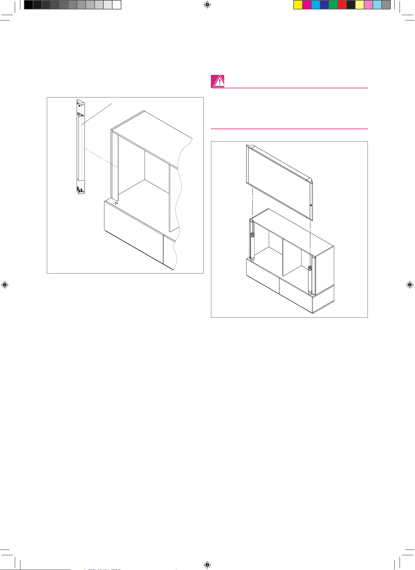
Konstruktionsprinzip
Aluminiumrahmen
Akustisch wirksame Rückwand
mit Stoffbespannung
Front wahlweise akustisch
wirksam oder mit Whiteboard
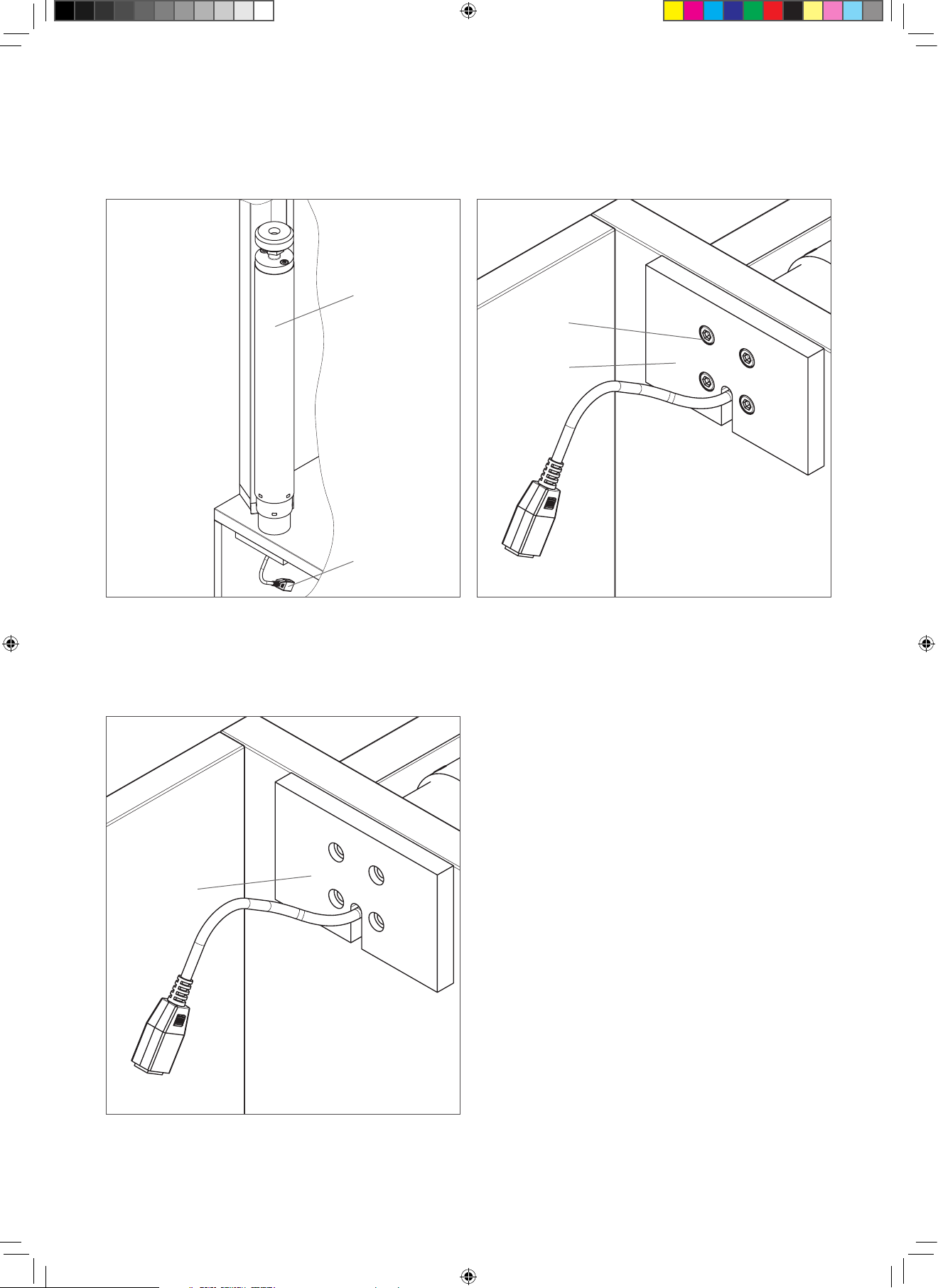
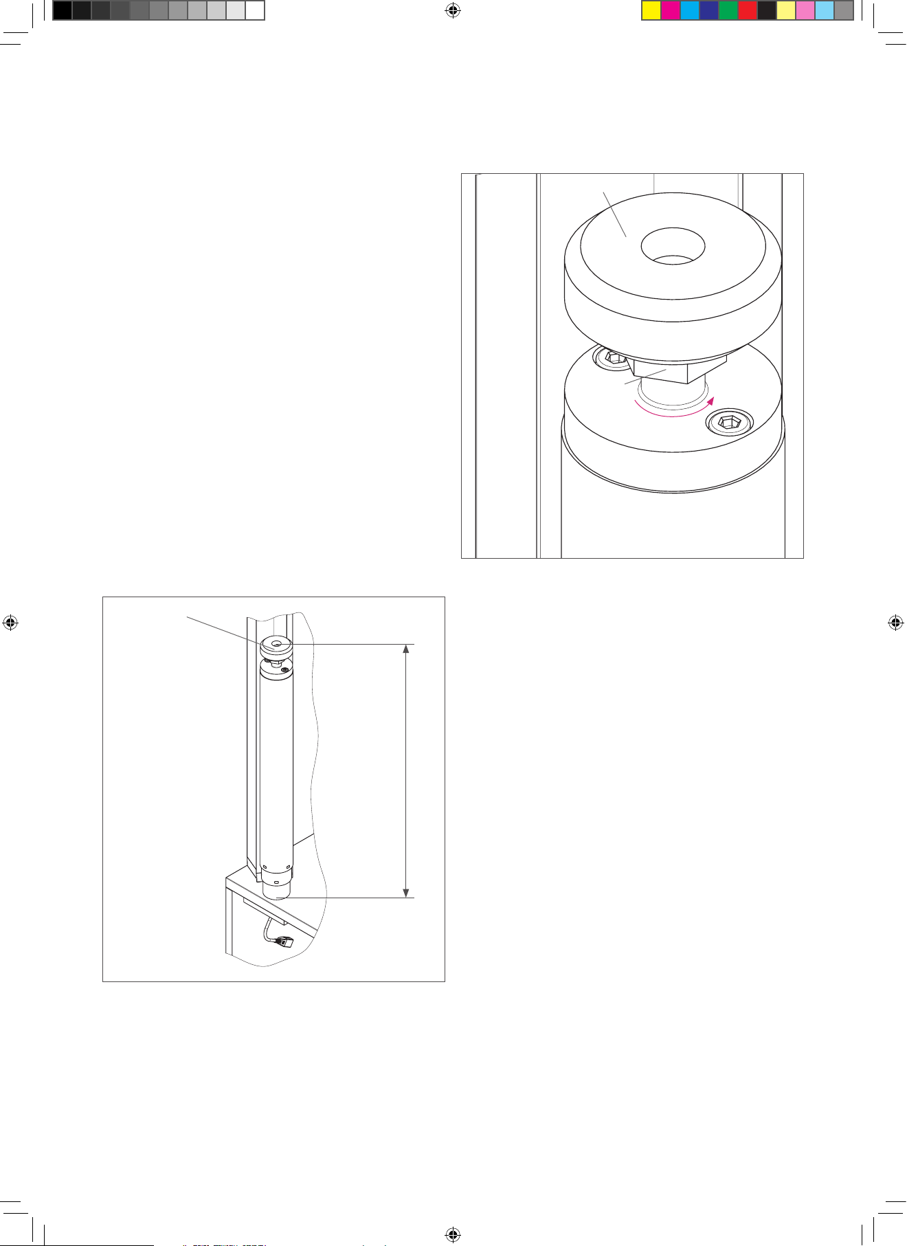
Elektromotorische Hubsäule
Höhenverstellung
Individuelle, stufenlose
Höhenverstellung
(elektromotorisch)
Max. Hublänge 750 mm
Auf-/Ab-Funktion über
Funkübertragung
Langlebige Batterie inklusive
Elektr. Anschlussdaten
Netzspannung 230 V AC 50-60 Hz
(120 V AC, 60 Hz auf Nachfrage)
Spannungsversorgung durch Konturenstecker (CEE 7/17),
Kabellänge ca. 3 m
Max. Stromverbrauch im
Standby-Modus:
0,1 W
Stromverbrauch im Betrieb ca. Max. 200 W
Schutzabschaltung nach 6 Minuten Betrieb pro
Stunde oder nach 2 Minuten
Dauerbetrieb
Verfahrdaten
Hublänge 750 mm
Max. Kraft 1500 N
Verfahrgeschwindigkeit 60 mm/s
Reduzierte
Verfahrgeschwindigkeit für
vollständige Abwärtsfahrt
20 mm/s
Geräuschpegel beim Verfahren < 70 dB(A)
Umgebungsbedingungen
Umgebungstemperatur + 10 °C bis + 40 °C
Betriebsumgebung Im Inneren von Gebäuden
(Büroumfeld). Nicht in
Feuchträumen betreiben.
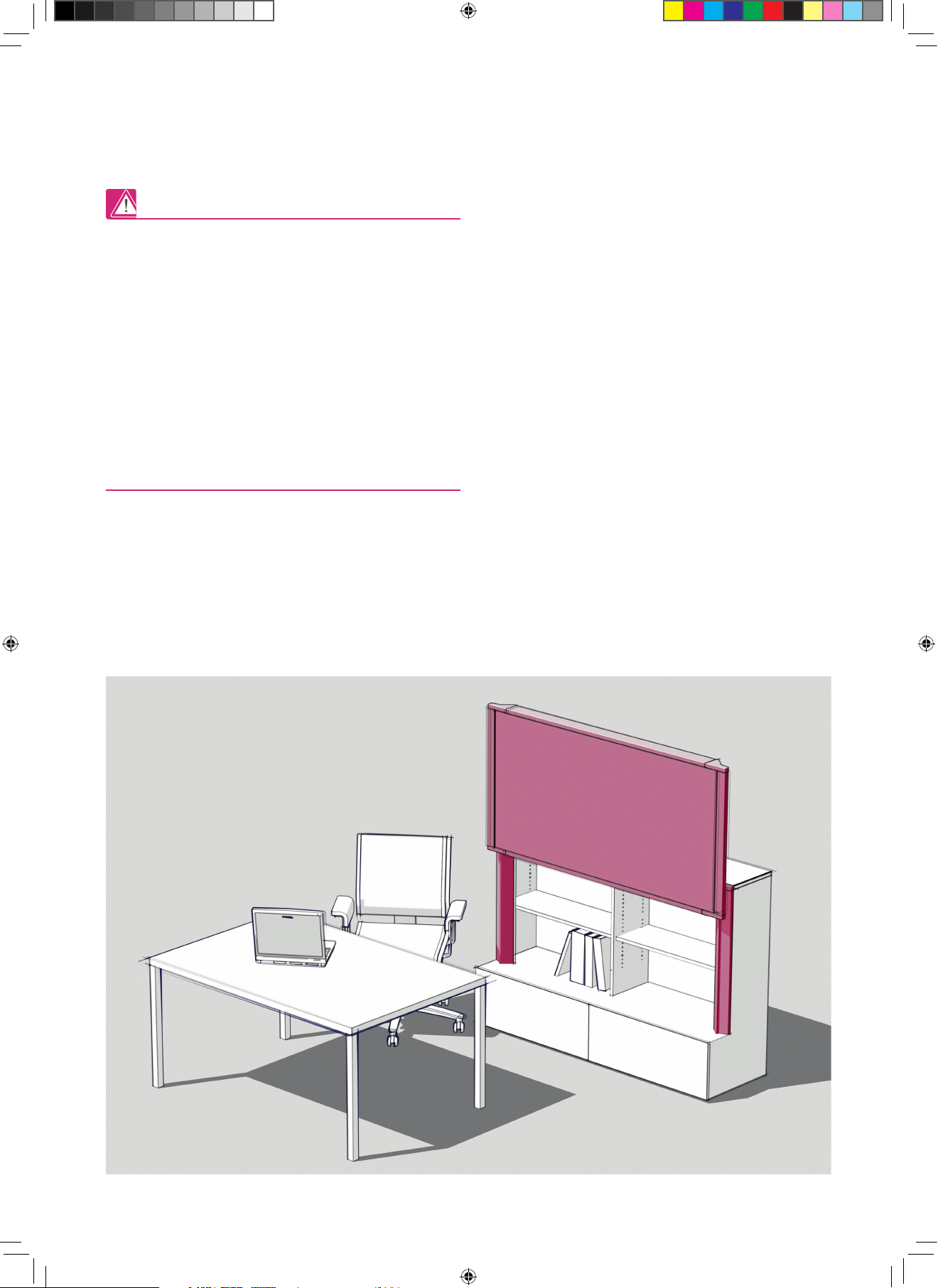
Technische Daten:
RAUWORKS Front,
Gesamt-ZSB "Accoustic",
Geometrie aus REHAU-Zeichnung
PKS-16077 B vom 08.11.2012 ,
( ohne Hubsäulen dargestellt )
für Einbauanleitung.
M1:10
08.11.12 Fa. REHAU AG+Co,
Konstruktion CCT-IS,
Kiessling 2424
RAUWORKS Front,
2 Stück Hubsäule DL14 Fa.Linak mit Verstellelement oben
Geometrie aus REHAU-Zeichnungen
PKS-16076 B / PKS-16077 B vom 08.11.2012 ,
für Einbauanleitung.
M1:5
08.11.12 Fa. REHAU AG+Co,
Konstruktion CCT-IS,
Kiessling 2424
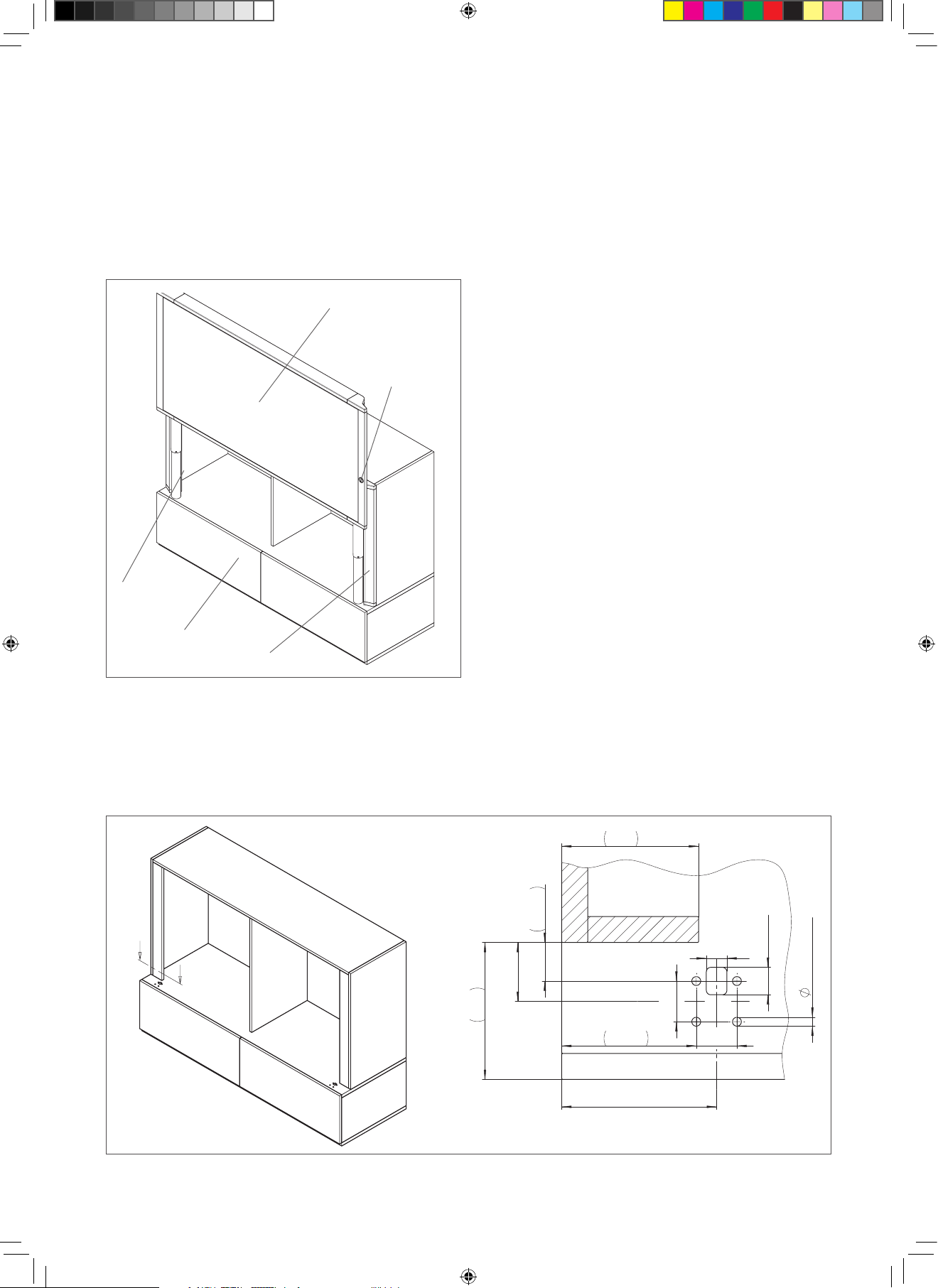
RAUWORKS Front,
Befestigungsplatte für Hubsäule unten,
Geometrie aus REHAU-Zeichnung
PKS-16078 B vom 08.11.2012 ,
für Einbauanleitung.
M1:1
08.11.12 Fa. REHAU AG+Co,
Konstruktion CCT-IS,
Kiessling 2424
RAUWORKS Front,
Befestigungsschraube M6x45 DIN7984
Geometrie aus REHAU-Zeichnung
PKS-16078 B vom 06.11.2012 ,
für Einbauanleitung.
M2:1
08.11.12 Fa. REHAU AG+Co,
Konstruktion CCT-IS,
Kiessling 2424
RAUWORKS Front,
Motorkabel Fa.Linak
Geometrie aus REHAU-Zeichnung
PKS-16078 B vom 06.11.2012 ,
für Einbauanleitung.
M1:5
08.11.12 Fa. REHAU AG+Co,
Konstruktion CCT-IS,
Kiessling 2424
RAUWORKS Front,
Netzkabel Fa.Linak
Geometrie aus REHAU-Zeichnung
PKS-16078 B vom 08.11.2012 ,
für Einbauanleitung.
M1:2
08.11.12 Fa. REHAU AG+Co,
Konstruktion CCT-IS,
Kiessling 2424
RAUWORKS Front,
Funkempfänger mit Kabel Fa.Linak
Geometrie aus REHAU-Zeichnung
PKS-16078 B vom 08.11.2012 ,
für Einbauanleitung.
M1:2
08.11.12 Fa. REHAU AG+Co,
Konstruktion CCT-IS,
Kiessling 2424
RAUWORKS Front,
Controlbox CBD6 Fa.Linak
Geometrie aus REHAU-Zeichnung
PKS-16078 B vom 08.11.2012 ,
für Einbauanleitung.
M1:2
08.11.12 Fa. REHAU AG+Co,
Konstruktion CCT-IS,
Kiessling 2424
B41604_RAUWORKS_front_elektr_Montageanleitung_DE_EN_FR3_eps.indd 5 4/26/2013 5:15:00 PM