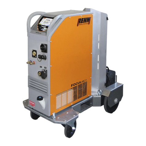
REHM FOCUS.ARC P 300 User manual

GB
OPERATING INSTRUCTIONS
MIG/MAG impulse welding systems
FOCUS.ARC P 250 - 450

Operating instructions
MIG/MAG impulse welding systems
FOCUS.ARC P 250
FOCUS.ARC P 300
FOCUS.ARC P 350
FOCUS.ARC P 400
FOCUS.ARC P 450
REHM GmbH u. Co. KG
Ottostr. 2
D-73066 Uhingen
Telephone: 07161/3007-0
Telefax: 07161/3007-20
E-Mail: rehm@rehm-online.de
Internet: http://www.rehm-online.de
Document No.: 730 2600
Date of issue: 18/02/2019
©REHM GmbH u. Co. KG, Uhingen, Germany 2018
The content of this description is the property of REHM GmbH u. Co. KG
The copying and distribution of this document, its use and communication of its
contents are strictly prohibited unless expressly authorized.
Offenders are liable to damages. All rights reserved in the event of patent, utility
model or design patent.
The manufacture based on these documents is not allowed.
Subject to change.
Name
Type
Manufacturer

List of contents
3
List of contents
Product identification 2
1INTRODUCTION..............................................................................................................................6
1.1 Foreword.........................................................................................................................................6
1.2 General description .......................................................................................................................7
1.2.1 The principle of the inert gas metal welding process.......................................................................8
1.2.2 Intended use ....................................................................................................................................8
1.3 Symbols used.................................................................................................................................9
2SAFETY INSTRUCTIONS.............................................................................................................10
2.1 Warning symbols in these operating instructions ...................................................................10
2.2 Warning symbols on the system................................................................................................10
2.3 Notes and requirements..............................................................................................................11
3UNIT DESCRIPTION .....................................................................................................................13
4FUNCTIONAL DESCRIPTION......................................................................................................18
4.1 Overview of the operating elements ..........................................................................................18
4.2 Control panel description............................................................................................................19
4.2.1 Operating elements........................................................................................................................19
4.2.2 Operating elements........................................................................................................................20
4.3 Switching on.................................................................................................................................23
4.4 Peculiarities of the operating panel ...........................................................................................23
5CORNER MENU FUNCTIONS......................................................................................................24
5.1 Corner menu welding processes (top left)................................................................................24
5.1.1 Conventional MIG/MAG(MSG) welding .........................................................................................24
5.2 Corner menu operating mode (top right)...................................................................................24
5.2.1 2 cycle operating mode..................................................................................................................25
5.2.2 2 cycle operating mode with slope-down (Slope) ..........................................................................26
5.2.3 4 cycle operating mode..................................................................................................................27
5.2.4 4 cycle operating mode with slope-down (Slope) ..........................................................................28
5.2.5 Spot................................................................................................................................................29
5.2.6 Spot with slope-down (Slope) ........................................................................................................30
5.2.7 2 cycle interval ...............................................................................................................................31
5.2.8 2 cycle interval with slope-down (Slope)........................................................................................32
5.3 Corner menu characteristic curve..............................................................................................33
5.4 Corner menu welding process ...................................................................................................33
5.4.1 Power Arc.......................................................................................................................................33
5.4.2 Power Puls II..................................................................................................................................33
5.4.3 Focus Puls .....................................................................................................................................34
5.4.4 Root................................................................................................................................................34
5.5 Display panel Welding current (A) .............................................................................................34
5.6 Display panel Voltage (V)............................................................................................................34
5.7 Display panel Dynamic correction (SDI)....................................................................................34
5.8 Display panel LBL correction .....................................................................................................35

List of contents
4
5.9 Display panel Material thickness............................................................................................... 35
5.10 Display panel Wire feed speed .................................................................................................. 35
5.11 Characteristic curve info bar ..................................................................................................... 35
6. SUBMENUS.................................................................................................................................. 36
6.1 MSG parameters.......................................................................................................................... 36
6.1.1 Parameter settings ........................................................................................................................ 36
6.1.2 Setting the MSG welding parameters ........................................................................................... 36
6.1.3 Explanation of welding parameters............................................................................................... 38
6.2 Language menu........................................................................................................................... 40
6.3 Saving and loading jobs............................................................................................................. 41
6.3.1 Save job......................................................................................................................................... 41
6.3.2 Load job......................................................................................................................................... 43
6.3.3 Delete job ...................................................................................................................................... 44
6.3.4 Rename job................................................................................................................................... 45
6.4 Setup submenu ........................................................................................................................... 46
7CONTROL LAMPS....................................................................................................................... 48
8OTHER FUNCTIONS.................................................................................................................... 49
8.1 Threading..................................................................................................................................... 49
8.2 Gas test ........................................................................................................................................ 49
8.3 Water recirculation cooling........................................................................................................ 50
8.4 Temperature monitoring of the power units............................................................................. 50
8.5 External cooling of the power units .......................................................................................... 50
8.6 Fan and water pump control...................................................................................................... 50
9ACCESSORIES AND OPTIONS.................................................................................................. 51
9.1 Unit versions, accessories and options ................................................................................... 51
10 COMMISSIONING ........................................................................................................................ 55
10.1 Safety instructions...................................................................................................................... 55
10.2 Working under elevated electrical risk in accordance with the regulations......................... 55
10.3 Positioning the welding unit ...................................................................................................... 55
10.4 Connecting the welding unit...................................................................................................... 56
10.5 Cooling the welding unit............................................................................................................. 56
10.6 Water cooling for MIG/MAG welding torches........................................................................... 56
10.7 Connecting the welding cables ................................................................................................. 56
10.8 Connecting the torch .................................................................................................................. 56
10.9 Inserting the wire........................................................................................................................ 57
11 OPERATION................................................................................................................................. 58
11.1 Safety instructions...................................................................................................................... 58
11.2 Checks before switching on ...................................................................................................... 58
11.3 Connecting the grounding cable............................................................................................... 58
11.4 Practical instructions for use..................................................................................................... 58

List of contents
5
12 FAULT............................................................................................................................................61
12.1 Safety instructions.......................................................................................................................61
12.2 Table of faults...............................................................................................................................61
12.3 Error messages............................................................................................................................63
13 MAINTENANCE AND REPAIR.....................................................................................................64
13.1 Safety instructions.......................................................................................................................64
13.2 Maintenance table........................................................................................................................65
13.3 Cleaning the inside of the unit....................................................................................................65
13.4 Cooling water check ....................................................................................................................66
13.5 Proper disposal............................................................................................................................66
14 CIRCUIT DIAGRAMS....................................................................................................................67
14.1 Characteristic curve current source ..........................................................................................70
15 COMPONENTS AND SPARE PARTS..........................................................................................72
15.1 Characteristic curve wire feeding unit.......................................................................................72
16 TECHNICAL DATA .......................................................................................................................77
17 INDEX ............................................................................................................................................78

Introduction
6
1Introduction
1.1 Foreword
Dear Customer,
You have purchased a REHM inert gas welding system, a renowned German
brand name.
We thank you for the confidence you have placed in our quality products.
Only components of the highest quality are used in FOCUS.ARC P welding systems.
To enable a long service life even under the toughest conditions all REHM
equipment is manufactured using only parts that comply with our strict quality
demands.
The FOCUS.ARC P has been developed and designed according to the generally
accepted rules of technology and safe operation. All relevant legal regulations have
been observed and complied with. Conformity is declared and is marked with the CE
symbol.
REHM welding systems are manufactured in Germany and therefore bear the "Made
in Germany" quality label.
REHM strives to immediately take advantage of technical progress and reserves the
right to adapt the design of the welding equipment at any time to the latest technical
requirements.

Introduction
7
1.2 General description
Figure 1: FOCUS.ARC P450 WS
(Figure does not illustrate standard equipment)

Introduction
8
1.2.1 The principle of the inert gas metal welding process
With the inert gas metal welding process an electric arc burns between a melting
wire electrode and the workpiece. Argon, carbon dioxide (CO2) or a mixture of these
or other inert gasses are used.
The positive pole usually flows from the current contact tips to the wire electrode and
the negative pole is connected to the workpiece. An electric arc forms between the
wire electrode and the workpiece that melts both the wire electrode and the
workpiece. The wire electrode is therefore the conductor for the arc and weld filler
material.
The wire electrode and the weld pool are protected against the influence of ambient
air by the inert gas, which flows continuously from the inert gas nozzle that is
arranged concentrically around the electrode.
1.2.2 Intended use
FOCUS.ARC P welding systems may only be used for MIG/MAG welding.
REHM welding units are designed for welding various different metallic materials
such as unalloyed and alloyed steels, stainless steels, aluminium and CuSi3.
Please also observe the special rules that apply to your applications.
REHM welding machines are designed for use in both hand-held and machine-
guided operation.
REHM welding machines are, except when this is expressly stated in writing by
REHM, only for sale to commercial / industrial users and are only intended to be
used by commercial / industrial users. The machines may only be operated by
persons who trained in the use and maintenance of welding equipment.
Welding power sources may not be installed in areas with increased electrical risk.
This manual contains rules and guidelines for the intended use of your system. Only
compliance with these guidelines shall be considered as proper use. Risks and
damages incurred due to any other use is the responsibility of the operator. Use
under special requirements may necessitate the observance of particular
regulations.
If in doubt, ask your competent safety officer or contact the REHM customer service
department.
The special instructions listed in the supplier documentation for intended use must
be observed.
National regulations also apply without restriction to the operation of the system.
Welding power sources may not be used to defrost pipes.
Intended use also includes compliance with the prescribed assembly, disassembly
and reassembly, commissioning, use, maintenance and disposal measures. Please
pay particular attention to the information in Section 2 Safety instructions and
Section 15.5 Proper disposal.
The system may only be operated under the aforementioned conditions. Any other
use is considered unintended use. The consequences of unintended use rests with
the operator. Welding power sources may not be used to defrost pipes.

Introduction
9
1.3 Symbols used
•Enumerations proceeded by a bullet point: General enumerations
Enumerations proceeded by a square: Work or maintenance steps that must be
performed in the order listed.
➔Section 2.2, Warning symbols on the system
Cross section: here to Section 2.2, Warning symbols on the system
Bold text is used for emphasis
Note!
... indicates practical tips and other particularly useful information.
The safety symbols used in this manual: ➔Section 2.1
Typographic
distinctions
Safety
symbols

Safety information
10
2Safety instructions
2.1 Warning symbols in these operating
instructions
This or a symbol that more accurately specifies the risk can be found in all
of the safety instructions given in these operating instructions where there
is danger to life and limb.
One of the signal words below (Danger!, Warning!, Caution!) is used to
indicate the severity of the risk:
Danger! …warning of immediate danger.
Death or serious injury may result if the warning if not heeded.
Warning! ... of a potentially dangerous situation.
Death or serious injury may result if the warning is not heeded.
Caution! … warns of a potentially harmful situation.
Slight or minor injuries or property damage may result if the warning is not
heeded.
Important!
Notice of a potentially harmful situation. The product or an object in the
vicinity may be damaged if the warning is not heeded.
Materials that are hazardous to health or the environment.
Materials/operating materials that must be handled or disposed of in a
legally conformant way.
2.2 Warning symbols on the system
identify hazards and hazard sources on the system.
Danger!
Risk of electrical shock!
Non-observance mas result in death or injury.
Warnings and
symbols

Safety information
11
2.3 Notes and requirements
The system was developed and designed by the generally accepted rules of
technology.
Nevertheless, residual dangers to the life and limb of the operator or the risk of
damage to the system or other property may still arise in the use of the system.
Safety equipment must never be dismantled or put out of operation as this will
result in dangerous hazards and the intended use of the system is no longer
guaranteed. The dismantling of safety devices for equipping, repairing and
maintenance is described in detail. The safety devices must be refitted
immediately on completion of such work.
When using external aids and agents (for example, solvents for cleaning) the
user of the system is responsible for ensuring the safety of the unit.
All safety instructions and warnings and the nameplate on / near the system must
be kept visible and legible.
The occupational safety and health regulations serve as safety references. They
must be observed.
In addition to the safety instructions listed in this section, the safety instructions
contained in the current text must also be observed.
Beside the advice given in these operating instructions, the general safety and
accident prevention regulations (in Germany, among others UVV BGV A3, TRBS
2131 and BGR 500 Chapter 2:26 (previously VGB 15): "Welding, cutting and
allied processes" and particularly the conditions for arc welding and cutting
contained therein or the corresponding national regulations) must be observed.
Also observe the safety information signs on the factory floor of the operator.
REHM welding machines are, except when this is expressly stated in writing by
REHM, only for sale to commercial / industrial users and are only intended to be
used by commercial / industrial users.
The FOCUS.ARC P MIG/MAG gas welding equipment is designed in accordance
with EN 60974-1 Arc welding equipment - welding power sources for overvoltage
category III and pollution degree 3 and in accordance with EN 60974-10 Arc
welding equipment - electromagnetic compatibility (EMC) and may only be used
on mains supply systems which have a three-phase four-wire system with
earthed neutral conductor.
FOCUS.ARC P inert gas welding systems may only be used
•as intended
•in an absolutely perfect condition
Hazards of non-
compliance
Safety information
Applications

Safety information
12
The FOCUS.ARC P MIG/MAG gas welding equipment has been subjected to a
safety test and acceptance. In the event of incorrect operation or misuse, there is
a danger to
•life and limb of the operator,
•the machine and other material assets of the operator
•the efficient work of the machine
All persons involved in the installation, commissioning, operation, maintenance
and repair of the machine must
•be appropriately qualified
•strictly observe these operating instructions.
Your safety is at stake!
FOCUS.ARC P MIG/MAG gas welding equipment should be operated only by
persons who are trained and instructed in the use and maintenance of welding
equipment. Only qualified, assigned and trained personnel may work on and with
the system.
The operator is responsible for third parties in the work area. The responsibility
for this machine must be precisely defined and adhered to. Unclear
responsibilities are a safety risk.
The operating company must
•make the operating instructions accessible to the operator and
•ensure that the operator has read and understood them.
Connect a lockable switch in front of the machine to prevent unauthorised
operation.
These operating instructions contain important information on how this unit can
be operated safely, properly and economically. A copy of the operating
instructions must be constantly at hand in a suitable place at the site of use of the
system. Before using the system be sure to read the information compiled in
these operating instructions. These include important instructions on use of the
equipment that enable the full technical advantages of the RHEM equipment to
be exploited. See also the information on repair and maintenance, operating
safety and functional reliability.
These operating instructions are not a substitute for the practical teaching by the
REHM service personnel.
Documentation for any additional operation that may be present must also be
observed.
Changes to the system or the mounting or incorporation of additional equipment
is not permitted. Doing so will invalidate any warranty and liability claims.
Third-party intervention and putting out of operation of safety devices invalidates
all warranty claims.
High power units can affect the mains voltage due to their high power
consumption. Therefore, connection restrictions, requirements for a maximum
permissible mains impedance or requirements for a minimum necessary
available power at the connection point to the general mains supply may exist for
certain unit types (see technical data). If this is the case, the user of a unit - after
consulting the power supplier if necessary - must ensure that the unit may be
connected.
Purpose of the
document
Changes to
the system
Requirements on
the mains supply
Qualification of the
operating
personnel
Dangerous nature
of this machine

Function description
13
3Unit description
Figure 2: FOCUS.ARC P 450WS with case and water cooling unit
Front view (Figure does not illustrate standard equipment)

Function description
14
Figure 3: FOCUS.ARC P 300W, compact and water cooled
Front view (Figure does not illustrate standard equipment)

Function description
15
Figure 4: FOCUS.ARC P 450
Rear view (Figure does not illustrate standard equipment)

Function description
16
Figure 5: FOCUS.ARC P wire feed case

Function description
17
No.
Symbol
Function / description
1
Control panel - See "Description of controls"
2
Control panel push and rotary encoder
3
Welding torch connection (Euro connection)
4
Remote control socket (7 pin)
5
Connection coolant supply (Blue)
6
Connection coolant return (red)
7
Main switch for switching on/off the welding current source
8
Current socket "negative"
9
Current socket "positive"
10
Cooling air inlet
11
Inlet Filling Coolant Water cooling unit
12
Viewing window Stand Coolant Water cooling unit
13
Advanced trolley (option, non-standard)
14
Interface
15
Inert gas connection Welding torch
16
Power cable
17
Welding power sources
18
Water cooling unit (Option)
19
Cooling air outlet
20
Coil mandrel
21
Wire feeding unit
22
Gas test push button
23
Threading push button
Table 1 Equipment labelling on the front and back

Function description
18
4Functional description
4.1 Overview of the operating elements
Figure 6: Operating element and main screen FOCUS.ARC P

Function description
19
4.2 Control panel description
4.2.1 Operating elements
Controls
Function
Fig. 7 Main screen
Main screen
Operation via rotary encoder with push-
knob and buttons for menu selection in
the 4 corners of the screen
Fig. 8 Function buttons
Function buttons (from left to right)
Button
Submenu
“Submenu”
List of all
submenus
Button
Main screen
“Home”
Jumps directly
to the first
screen page
Button
Back
“Back”
Always jumps
back one level
Fig. 9 Corner function buttons
Corner menu selection buttons
Direct menu buttons for the selection
menus located in the 4 screen corners;
arranged around the rotary encoder.
Fig. 10 Rotary encoder with push-
knob
Rotary encoder with push-knob
Moves the pointer (cursor) on the
screen clockwise or counter clockwise.
Positions reached are highlighted in
colour and are activated by pressing
the rotary encoder knob.

Function description
20
4.2.2 Operating elements
Figure 11: Screen functions
No.
Symbols
Description / function
BF1
Corner menu welding processes
MSG welding
BF2
Corner menu operating modes
2 cycle
2 cycle with slope-down
4 cycle
4 cycle with slope-down
Spot
Spot with slope-down
Interval
Interval with slope-down
1
2
4
5
6
7
8
9
3
11
10
This manual suits for next models
3
Table of contents
Other REHM Welding System manuals

REHM
REHM SYNERGIC.PRO2 170-2 User manual

REHM
REHM TIG.STAR 170 DC User manual

REHM
REHM BOOSTER.PRO 250 User manual

REHM
REHM SYNERGIC.ARC 251 User manual

REHM
REHM Tiger 170 User manual

REHM
REHM BARRACUDA 45i User manual

REHM
REHM TIGER DIGITAL 230 AC/DC ULTRA User manual

REHM
REHM SYNERGIC.PRO 251 How to use

REHM
REHM FOCUS.ARC P Series How to use

REHM
REHM TIGER 170 DC User manual