Westweld NB-350MK User manual

MANUAL
INSTRUCTION
(PLEASE READ CAREFELLY BEFORE OPERATION)
NB-350/500MK
MIG/MAG/CO2WELDING MACHINE

Safety Depends on You
Huayuan arc welding and cutting equipments are designed and built with safety in mind. However, your overall safety can
be increased by proper installation.
DO NOT INSTALL, OPERATE OR REPAIR THIS EQUIPMENT WITHOUT READING THIS MANUAL AND THE SAFETY
PRECAUTIONS CONTAINED THROUGHOUT. And, most importantly, think before you act and be careful.
Special Attention (Very Important):
●AVOID FALLING DOWN WHEN THE WELDING MACHINE IS PLACED ON THE INCLINED PLANE.
●IT’S CAN NOT BE USED FOR UNFREEZING PIPELINES.
●THE SHIELD RANK OF THIS SERIES OF WELDING MACHINE IS IP21S, AND IT IS NOT SUTABLE FOR WORKING IN THE
RAIN.
Purchase Date:----------------------
Serial Number:----------------------
Machine Type:-----------------------
Purchase Place:----------------------

CONTENT
1Safety...................................................................................................................................................... 5
2Summary................................................................................................................................................. 1
2.1 Model instruction.............................................................................................................................1
2.2 Main features ...................................................................................................................................1
2.3 Usage ...............................................................................................................................................1
2.4 Working condition and environment................................................................................................1
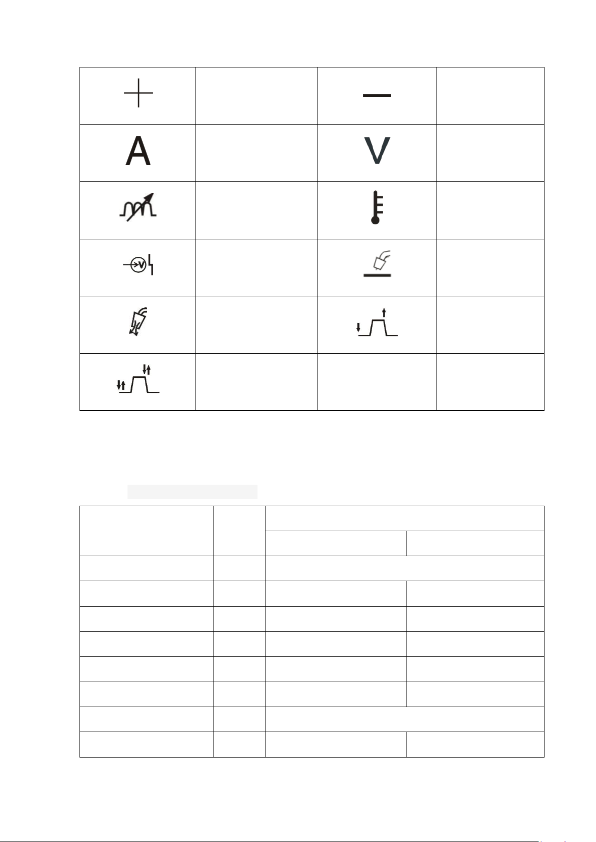
2.5 Symbol instruction...........................................................................................................................1
3Specifications.......................................................................................................................................... 2
3.1 Main technical parameters...............................................................................................................2
4Panel and function................................................................................................................................... 3
4.1 Front panel function.........................................................................................................................3
4.2 Down front panel .............................................................................................................................4
4.3 Rear panel instruction ......................................................................................................................5
5Installation .............................................................................................................................................. 5
5.1 Power supply requirement ...............................................................................................................5
5.2 Power cable connection ...................................................................................................................6
5.3 Welder and wire feeder connection..................................................................................................8
5.4 Gas cylinder and gas regulator connection .....................................................................................8
6Operation ................................................................................................................................................ 8
6.1 Pre-operation preparation and inspection confirmed items and methods and requirements............8
(1)Preparation of safety equipment...............................................................................................8
(2)Checking after connection .......................................................................................................9
(3)Wire installation.......................................................................................................................9
6.2 Weld operation...............................................................................................................................10
(1)4-Step weld operation(Non initial).........................................................................................10
(2)2-Step weld operation(Non initial and crater)........................................................................11
7Weld condition example........................................................................................................................ 12
8Working principle ................................................................................................................................. 15
8.1 Working principle ..........................................................................................................................15
8.2 Drawing .........................................................................................................................................15
8.3 Component list...............................................................................................................................16
9Maintenance and repairing.................................................................................................................... 16
9.1 Maintenance...................................................................................................................................16

9.2 Repairing........................................................................................................................................16
10 Common faults and eliminating methods ..................................................................................... 16
11 Packing List .......................................................................................................................................... 19
12 Annex............................................................................................................................................ 20
1、NB350MK diagram .........................................................................................................................20
2、NB500MK diagram ......................................................................................................................21

1Safety
Cautions
Arc and arc rays may harm health.
Arc welding can be hazardous. All performing welding workers ought to have health qualification that provided by authority
organization. Protect yourself and others from possible serious injury or death. Keep children away. Pacemaker wearers should
consult with their doctor before operating. Be sure that all installation, operation, maintenance and repair procedures are
performed only by qualified individuals.
1 Electric shock can kill: The electrode and work (or ground) circuits are electrically “hot” when the welder is
on. Do not touch these “hot” parts with your bare skin or wet clothing, Wear dry, hole-free gloves to insulate
hands. Users need to follow the below items to avoid electric shocks:
Insulate yourself from work and ground using dry insulation. Make certain the insulation is large enough to cover your full
area of physical contact with work and ground. Otherwise, use automatic or semiautomatic welding machines, DC welding
machines as possible as you can.
In semiautomatic or automatic wire welding, the electrode, electrode reel, welding head, nozzle or semiautomatic welding
gun are also electrically “hot”.
Always be sure the work cable makes a good electrical connection with the metal being welded. The connection should be as
close as possible to the area being welded.
Ground the work or metal to be welded to a good electrical (earth) ground.
Maintain the electrode holder, work clamp, welding cable and welding machine in good, safe operating condition. Replace
damaged insulation.
Never dip the electrode in water for cooling.
Never simultaneously touch electrically “hot”parts of electrode holders connected to two welders, because voltage between
the two can be the total of the open circuit voltage of both welders.
When working above floor level, please do wear safety belt to avoid falling or losing balance on electric shock.
2 Arc rays can burn: Use a shield with the proper filter and cover plates to protect your eyes from sparks and
the rays of the arc when welding or observing open arc welding. Head shield and filter lens should conform to
nation standards.
Use suitable clothing made from durable flame-resistant material to protect your skin and that of your helpers from the arc
rays.
Protect other nearby personnel with suitable, non-flammable screening and/or warn them not to watch the arc nor expose
themselves to the arc rays or to hot spatter or metal.

3 Fumes and Gases can be dangerous: Welding may produce fumes and gases hazardous to health. Avoid
breathing these fumes and gases. While working in limited room, use enough ventilation and/or exhaust to keep
fumes and gases away from the breathing zone, or use the respirator.
Shielding gases used for arc welding can displace air and cause injury or death. Always use enough ventilation, especially in
confined areas, to insure breathing air is safe.
Do not weld in locations near chlorinated hydrocarbon vapors coming from degreasing, cleaning or spraying operations. The
heat and rays of the arc can react with solvent vapors to form phosgene, a highly toxic gas, and other irritating products.
Read and understand the manufacturer’s instructions for this equipment and the consumables to be used, including the
material safety data sheet (MSDS) and follow your employer’s safety practices. Make sure they are asepsis and innocuity.
4 Spatter: Welding or cutting spatter can cause fire or explosion.
Remove fire hazards from the welding area. If this is not possible, cover them to prevent the welding sparks
from starting a fire. Remember that welding sparks and hot materials from welding can easily go through small
cracks and openings to adjacent areas. Avoid welding near hydraulic lines. Have a fire extinguisher readily available.
Where compressed gases are to be used in the field, special precautions should be used to prevent explosion.
When not welding, make certain that no electriferous part is touching the work piece or the work stage. Accidental contact
can create a fire hazard.
Do not weld containers or lines, which are not proved to be innocuity.
Do not heat, cut or weld tanks, drums or containers until the proper steps have been taken to insure that such procedures will
not cause flammable or toxic vapors from substances inside. They can cause an explosion even though they have been “cleaned”.
Spatter might cause burn. Wear leather gloves, heavy shirt, cuff-less trousers, high shoes and a cap over your hair to prevent
from burning by spatter. Wear the ear shield when performing sideways or face up welding. Always wear safety glasses with
side shields when being in a welding area.
The welding cables should be as close to the welding area as possible, and the short, the better. Avoid welding cables going
through the building framework, lifting chains, AC or DC cables of other welding machines and appliances. The welding
current is strong enough to damage them while having short circuit with them.
5 Cylinder may explode if damaged.
Make sure that the gas in the storage cylinder is qualified for welding, and the decompression flow meter,
the adapter and the pipe are all in good condition.
Always keep cylinders in an upright position securely chained to an undercarriage or fixed support.
Be sure to put the cylinder in the working space with no crash or shake, and far from welding area.
Never allow the electrode, electrode holder or any other electrically “hot”parts to touch a cylinder.
Keep your head and face away from the cylinder valve outlet when opening the cylinder valve.
Valve protection caps should always be in place and hand tight except when the cylinder is in use or connected for use.
6 Power: (For electrically powered welding and cutting equipment) Turn off input power before installation,
maintenance and repair to avoid accidents.
Huanyuan welding equipment is Ι class safeguard equipment; please install the equipment in accordance
with the manufacturer’s recommendations by specific persons.

Ground the equipment perfectly in accordance with the manufacturer’s recommendations.
7 Power:(For engine driven welding and cutting equipment)
Work in ventilated place or outdoors.
Do not add fuel near to fire or during engine starting or welding. When not working, add fuel after engine is
cooling down; otherwise, the evaporation of hot fuel would result in dangers. Do not splash fuel out of the fuel
tank, and do not start the engine until complete evaporation of the outside fuel.
Make sure that all the safeguard equipments, machine cover and devices are all in a good condition. Be sure
that arms, clothes and all the tools do not touch all the moving and rotating components including V belt, gear and
fan etc.
Sometimes some parts of the equipment have to be dismantled during maintenance, but you still have to keep the strongest
safety awareness .
Do not put your hand close to fans and do not move the brake handle while operating.
Please remove the connection between the engine and the welding equipment to avoid sudden starting during
maintenances.
When engine is hot, it is forbidden to open the airtight cover of the radiator water tank to avoid hurt by the hot vapor.
8 Electromagnetic: Welding current going though any area can generate electromagnetic, as well as the
welding equipment itself.
Electromagnetic would affect cardiac pacemaker, the cardiac pacemaker users should consult one’s doctor
first.
The effect of electromagnetic to one’s health is not confirmed, and it might have some negative effect to one’s health.
Welders may use following method to reduce the hazardous of electromagnetic:
a. Bundle the cable connected to the work piece and the welding cable together.
b. Do not enwind partially or entirely your body with the cable.
c. Do not place yourself between the welding cable and the ground (work piece) cable, if the welding cable is by your left
side, then the ground cable should be by your left side too.
d. The Welding cable and the ground cable are as short as possible.
e. D e. Do not work near to the welding power source.
9 Lifting equipment: carton or wooden boxes package the welding machines supplied by Huayuan. There is
no lifting equipment in its wrapper. Users can move it to the prospective area by a fork-lift truck, then open the
box.
If there are rings, the machine can be transited by rings. While Huayuan Welding Machine Manufacture
reminds users, there is potential risk to damage the welding machine. So it is better to push the welding machine
by its rollers unless special situations.
Be sure that the appurtenances are all removed off when lifting.
When lifting, make sure that there is no person below the welding machine, and remind people passing by

at any moment.
Do not move the hoist too fast.
10 Noise: Huayuan Welding Machine Manufacture reminds users: Noise beyond the limit (over 80 db) can
cause injury to vision, heart and audition depending on oneself. Please consult local medical institution. Use the
equipment after doctor’s permission would help to keep healthy.

1
2Summary
2.1 Model instruction
N B —□□□ MK
Production code
Rated welding current (A)
Semi-automatic welding
Gas shielded welder
2.2 Main features
● Panel simple, easier parameters set and operation.
● Arc characteristic function is adjustable, suitable different welding condition.
● Crater current, crater voltage can be separately set, suitable different type welding.
●With gas checking function, easy to set the gas flow.
● With protection function of over-heating and lack-voltage, get more stable operation.
2.3 Usage
Suitable for carbon steel industries which use CO2/MAG welding process, specially used in building, bridge steel
structure, project machinery, etc.
2.4 Working condition and environment
If the following conditions are not met, the welding performance may not meet the specifications of the technical
specifications, and even damage the welder!
●Ambient temperature range
When welding: -10℃~40℃;
Transport and store : -20~+55℃;
● Relative humidity:40℃≤50%;20℃≤90%
● Ingress protection IP21S, not suitable use or store under raining or snowing.
● The dust, corrosive and acid air or material should be within normal range, except the air come from the welding
process.
● The distance between the power source and wall or other close things should be more than 30cm. The distance
between two machines should be more than 30cm.
● It should be stored in a dry and windy place to prevent the sunshine and rain.
● The elevation should be less than 1000m;
2.5 Symbol instruction
Symbol list as follows:
Please read manual
Ground connect

2
Positive
negative
Current
Voltage
Arc characteristics
Overheat
Lack-voltage
MIG/MAG
Gas check
Non-crater
With crater
Table 1 Symbol instruction
3Specifications
3.1 Main technical parameters
Item
Unit
Model
NB-350MK
NB-500MK
Input power
V/Hz
3~380±15%50/60
rated input capacity
KVA
17.4
23.8
rated input current
A
26.5
36.2
rated output current
A
350
500
rated output voltage
V
31.5
39
rated non-load voltage
V
69
83
duty cycle
-
60%(40℃)
efficiency
-
87%
89%

3
power factor
-
0.73
0.92
output current
A
40~350
60~500
voltage adjustment
V
14~40
14~50
Wire feeding adjustment
m/min
1~22
Crater current
A
40~350
60~500
Crater voltage
V
16~31.5
16~39
Suitable wire diameter
mm
Ø 0.8、Ø 1.0 、Ø 1.2
Ø 1.0 、Ø 1.2、Ø 1.6
cooling mode
-
Air cooling
Insulation grade
-
F
Ingress protection
-
IP21S
Dimension(L*W*H)
mm
520×295×550
560×295×570
Net weight
kg
28
32
Table 2 Main technical parameter
4Panel and function
4.1 Front panel function
Up panel function as follows fig.1
Fig.1 Up front panel
(1)Overheat indicator: When the temperature inside the machine is too high, this indicator will light, and the welder

4
will turn off the output;
If the air inlet or outlet or the air duct is blocked, the fan rotates abnormally, the ambient temperature is too high,
and the welding machine is overloaded and used continuously, etc., the internal temperature will be too high;
When the temperature in the standby falls below the temperature protection point, the indicator will go out and
the welder will automatically return to standby.
(2)Input fault: When the power supply of the welder is lower than 300V, this indicator will light and the welder will
turn off the output.
(3)Current meter: When the welding torch switch is not pressed, the relative value of the wire feeding speed is
displayed;
The actual welding current value is displayed when the torch switch is pressed.
(4)Crater current: used for crater current adjustment.
(5)Electric arc property knob: used to adjust the rate of current change during the droplet transfer during welding.
This knob adjustment will directly affect the softness and hardness of the arc, the size of the splash, the formation
of the weld and the stability of the arc combustion. It is in the standard state at the “0” position and meets the
needs of most normal welding. The left-hand adjustment knob is scaled from “0” to “-5”, the arc is gradually
hardened, suitable for small gauge welding, the right-hand rotation adjustment is from “0” to “+5” scale, the arc is
gradually softened, suitable for medium specification and large specification welding. .
Note: The arc hard splash is slightly larger, and the arc soft splash is small;
(6)“welding/check gas”: When switching to the "check gas”, set or check the flow rate of the shielding gas before
welding, and after the requirements are met, switch to the "welding" position, the gas is automatically controlled;
(7)Crater switch: Used to switch “2-step/4-step”function switch.
(8)Crater voltage: used for crater voltage adjustment.
(9)Voltage meter: The preset welding voltage value is displayed when the welding torch switch is not pressed;
The actual welding voltage value is displayed when the torch switch is pressed.
4.2 Down front panel
Down panel function as follows fig.2
Fig.2 Front panel function

5
(1) Control cable socket: Used to connect the wire feeder control cable.
(2) Welder output positive pole: used to connect the wire feeder welding cable.
(3) Welder output negative: used to connect the workpiece connection cable.
4.3 Rear panel instruction
Rear panel instruction as follow Fig.3:
Fig.3 Rear panel function
(1) Power over-current protection switch: When the welder has abnormal input over-current, disconnect the power supply
to protect it. This switch is for protection only. Please install a power switch when the welder is installed.
(2) Heater power connector: The power socket of the gas heater, the output voltage is AC36V/1.2A.
(3) Three-phase power cable junction box: The three-phase power cable of the welder is connected to the connection
end.
(4) Grounding nut: used to connect the welder to the earth.
(5) Three-phase power cable fixed clamp: used to fix the three-phase power input line.
5Installation
5.1 Power supply requirement
(1)Power supply: 3~50/60Hz 380VAC.
(2)Grid voltage fluctuation range: <±15%.
(3)Frequency fluctuation range: <±1%.
(4)Three-phase voltage imbalance rate:<±5%.
(5)When using the engine generator: The generator output power is required to be more than twice the rated input
power of the welding power source, and the compensation coil is provided.

6
5.2 Power cable connection
Please refer to Figure 4 to connect the power supply cable of the welder:
(1) Installation must comply with national and local standards - only by professionals;
(2) The user must turn off the power switch in the power distribution box before connecting, and start connecting after
ensuring that the power is turned off;
(3) The power supply for this product is three-phase 380V AC 50/60Hz. Users should use the corresponding distribution box,
air switch (circuit breaker) and power cord. The selected distribution box and power cord must meet the relevant national
standards.
The conditions for the user's power supply should be as follows:
Specification
NB-350MK
NB-500MK
Switch capacitor(A)
40
63
Fuse capacity(A)
32
40
Power cable cross-sectional
area(mm2)
≥4
≥6
Earth cable(mm2)
≥4
≥6
Table 3 Switchboard parameter requirements table
(1)Power cable connection
The connection must be made by a licensed electrician using cables and plugs that comply with local and national electrical
standards.
(2)Earth cable connection
Use a wire to connect the grounding screw on the backplane of the power supply to the ground. The cross-sectional area of
the wire must meet the requirements of Table 3. The grounding method is implemented in accordance with relevant
national standards.

7
Fig.4 Welder installation

8
5.3 Welder and wire feeder connection
Please refer to fig.4 to connect:
Connect one end of the negative output cable to the “-” output terminal block of the welder and the other end to the
work-piece.
(2) Connect one end of the positive output cable to the “+” output terminal block of the welder and the other end to the
wire feeder connector.
(3) Connect the air plug (six-core) of the wire feeder control cable to the welder end control cable socket (six-core), and
tighten the ring nut to connect the other end of the control cable to the wire feeder.
(4) The torch connector is fully inserted into the guide groove, rotate 90°clockwise after insertion, and then tighten the
fastening screw; connect the gas pipe of the torch to the gas outlet connector of the wire feeder, and tighten the crimp nut;
Insert the control plug into the guide slot and insert it into the wire feeder control socket (two cores) and tighten the ring
nut.
5.4 Gas cylinder and gas regulator connection
The connection between the gas cylinder and the gas regulator is shown in Figure 4:
(1) Install the gas regulator on the cylinder and tighten the mounting nut.
(2) Connect the plug of the gas heater to the heater power socket on the rear panel of the welder.
(3) Connect the gas supply pipe of the wire feeder to the gas output connector of the gas heater and press it with the hose
clamp.
6Operation
6.1 Pre-operation preparation and inspection confirmed items and methods and
requirements
(1)Preparation of safety equipment
Safety equipment as the follows Fig .5 :
Figure 5
a) Wear fur gloves and safety shoes to protect the skin and bare parts;

9
b) Wear a shield filter glass that match with different welding current to protect eyes;
c) There should be ventilation in the welding place to prevent breathing in deleterious gas.
Weld current
100A below
100A~300A
300A above
Photo protection
degree
No.09 , No.10
No.11 , No.12
No.13 , No.14
Table 4 The selection principal and reference of filtering glass
(2)Checking after connection
All items specified in the “Installation” in item 5 of this manual are checked one by one and confirmed without errors.
Switch operation and gas flow adjustment
Step 1: Turn on the power switch of distribution box;
Step 2: Press “weld/check gas”knob to check gas status.
Step 3: After unscrewing the gas cylinder switch, slowly unscrew and adjust the flow adjustment knob switch of the gas flow
meter so that the indication value on the flow-meter is the welding required value.(Refer to table 6.)
Step 4: Press “weld/check gas” to “weld” status.
(3)Wire installation
The part name as the Fig.6 as follows:
Fig.6 Wire installation
Pre-operation preparation and inspection, confirmed items and methods, requirements:
Step 1: Confirm that the wire feeding groove diameter of the wire feeding wheel is the diameter of the welding wire.
Otherwise, the wire feeding wheel must be removed to select the wire feeding wheel diameter which is the same as the
diameter of the welding wire, and the groove is outside. Installed
Step 2: Pull down the handle of the wire feeder and lift the pressure arm;
Step 3: the wire spool is mounted on the wire spool, the wire spool of the wire
is adjusted to extend, and the manual nut is tightened. When the welding wire is out, the wire spool rotates

10
clockwise when the wire is out;
Step 4: the welding wire passes through the correcting wheel (or guiding tube), the wire feeding wheel slot, and
then the guiding nozzle is inserted;
Step 5: pressing the pressing arm to press the welding wire, then lifting the handle to press the pressing arm, and
rotating the handle to a moderate pressure;
Step 6: Check the welding nozzle of the welding torch. The hole diameter should be the same as the diameter of the
wire used.
Step 7: Press the “manual wire feed” button of the wire feeder control box and adjust the “welding current
adjustment knob” to make the wire feed speed suitable until the 15-20 mm wire is exposed at the torch head.
(Manual wire feed switch is shown in Figure 7)
Fig.7 Wire feeder control box
Step 8: Adjust the screw sleeve of the wire handle to make the pressing force appropriate. The ideal pressing force is
that the wire can be transported normally. It is not suitable for slipping on the wire feeding wheel. Please adjust according
to the diameter of the wire marked on the adjusting handle.
DANGER! When jogging the wire, do not bring the end of the torch close to the face, eyes, or body. If the wire
suddenly jumps out into the face, eyes, or body, it will cause injury.
Note! Do not put your hands, fingers, hair, sleeves, clothes, etc. close to the rotating part of the wire feed wheel
when you feed the wire. If it is caught, it will cause injury.
6.2 Weld operation
(1)4-Step weld operation (Non initial)
● Suitable for welding long or medium thick plates
● The filling of the arc pit at the end of the welding can be achieved by welding with the arc;
● During the welding process, when the continuous arc breaking occurs for more than 0.5 seconds, the self-locking is
automatically released and the welding is completed.

11
● Enter the welding preparation state, and put the "2-step/4-step" switch of the welder panel to "4-step". Press the
torch switch and start to supply air and enter the pre-air supply state. Waiting for a period of time, the welding voltage
appears, and the slow wire feeding starts to enter the arcing state. After the arc is successfully turned on, the wire feeding
speed becomes a normal speed and a welding current is formed. At this time, the torch switch can be released and the
welding enters a self-locking state. At the same time, the "welding voltage adjustment knob" and "welding current
adjustment knob" of the wire feeder must be adjusted to achieve the best welding effect.
When welding to the end point, press the torch switch again to enter the arc adjustment state; at this time, adjust the
arcing voltage by adjusting the “arc voltage adjustment knob” and “arc current adjustment knob” on the front panel of the
welder. The current (or adjusted to the required value in advance, generally adjusted to 60 to 70% of the normal welding
current), so that the depression at the end of the welding can be filled. When the welding torch switch is released again, the
wire is immediately braked to stop, and the ignition state is reduced to the burn-in voltage. When the welding current is
zero, the arc-breaking is completed, the gas supply is stopped, and the welding process is completed.
(2)2-Step weld operation (Non initial and crater)
● Mainly used for spot welding, repeated short welding, thin plate welding.
● Press the button“2-step/4-step”to “2-step”, Turn on the torch(ON) and start welding, OFF torch then end welding.

12
7Weld condition example
The reference value values of the standard conditions are provided in Tables 6 and 7, which facilitates quick setting of
parameters. In actual welding, please correct it according to the material to be welded and the welding position to find
suitable welding conditions.
Table 6 Angle weld
Item
Thick
ness
(mm)
Angle
weld
length
(mm)
Wire
diameter
(mm)
Weld current
(A)
Weld
voltage
(V)
Weld
speed
(cm/min)
elonga
tion
(mm)
Gas flow
(L/ min)
Flat weld T type connector
Low speed condition
1.0
2.5~3
0.8
70~80
17~18
50~60
10
10~15
1.2
3~3.5
1.0
85~90
18~19
50~60
10
10~15
1.6
3~3.5
1.0、1.2
100~110
18~19.5
50~60
10
10~15
2.0
3~3.5
1.0、1.2
115~125
19.5~20
50~60
10
10~15
2.3
3~3.5
1.0、1.2
130~140
19.5~21
50~60
10
10~15
3.2
3.5~4
1.0、1.2
150~170
21~22
45~50
15
15~20
4.5
4.5~5
1.0、1.2
180~200
23~24
40~45
15
15~20
6
5~5.5
1.2
230~260
25~27
40~45
20
15~20
This manual suits for next models
1
Table of contents
Other Westweld Welding System manuals