Reiss CD10.1 User manual

Operating instructions
TARAtec sensors
CD10.1, OZ10.1
Februar 2022 (EN)
V3

Table of contents
2 / 40 TARAtec 10.1
Table of contents
1Information about these operating instructions..................................4
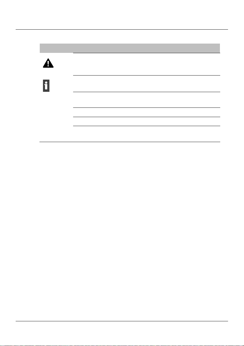
1.1 Symbols and displays ................................................................4
1.2 Associated documents...............................................................5
2Information on this product..................................................................6
2.1 Product description....................................................................6
2.2 Scope of supply.........................................................................8
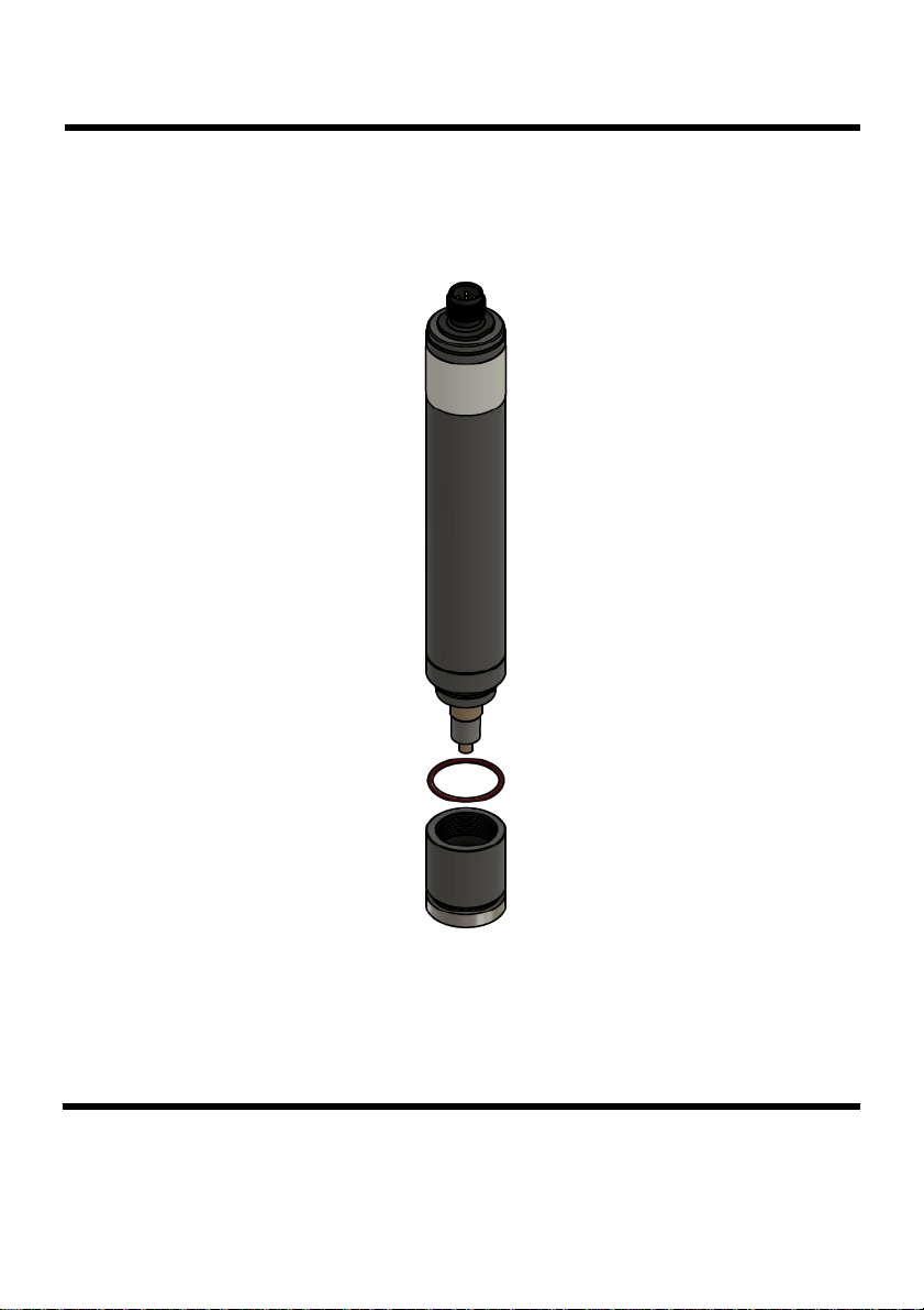
2.3 Product overview .......................................................................9
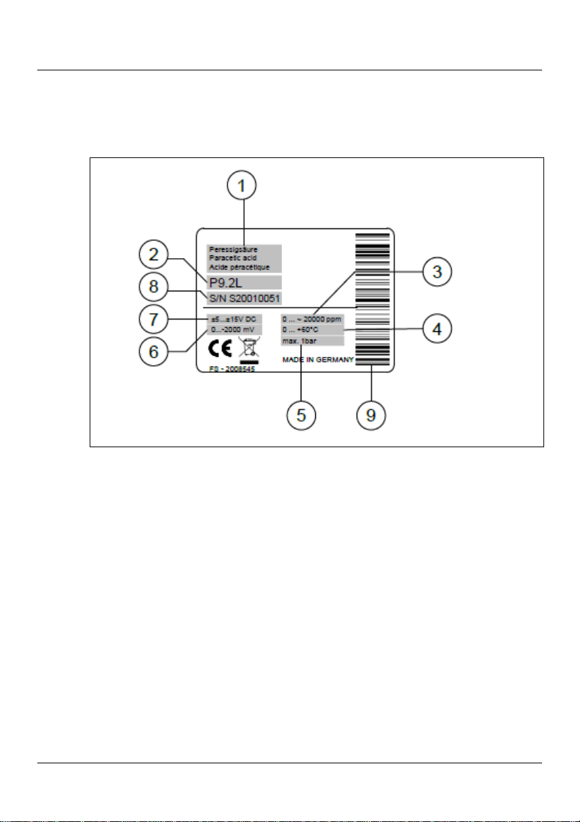
2.4 Name plate..............................................................................10
3Safety ..................................................................................................11
3.1 Use for the intended purpose...................................................11
3.2 Use other than for the intended purpose...................................11
3.3 Personal qualifications .............................................................12
3.4 Rebuilding and modifications....................................................12
3.5 Residual risks ..........................................................................12
4Commissioning...................................................................................16
4.1 Installation requirements..........................................................16
4.2 Preparation of the sensors.......................................................16
4.3 Insertion into the flow chamber.................................................18
4.4 Electrical connection................................................................19
4.5 Initial calibration.......................................................................21
5Calibration...........................................................................................22
6Removal ..............................................................................................24
7Maintenance........................................................................................25
7.1 Maintenance overview .............................................................25

Table of contents
TARAtec 10.1 3 / 40
7.2 Changing the electrolyte and membrane cap............................25
8Troubleshooting .................................................................................27
8.1 Fault overview..........................................................................28
8.2 Special checks.........................................................................35
9Technical data.....................................................................................38
10 Deinstallation and storage .................................................................38
11 Disposal ..............................................................................................38
12 Warranty..............................................................................................39
13 Liability disclaimer..............................................................................39

Information about these operating instructions
4 / 40 TARAtec 10.1
1 Information about these operating instructions
1.1 Symbols and displays
1.1.1 Safety and warning instructions
The hazard symbols and signal words listed below are used in these
operating instructions. They help you use the product safely, protect the
operating personnel against injuries and protect the operating company
against damage to property and additional costs.
Signal word Meaning
DANGER! DANGER means a hazard with a high degree
of risk which if not avoided will lead to death or
serious injury.
WARNING! WARNING means a hazard with a medium
degree of risk which if not avoided may lead to
death or serious injury.
CAUTION! CAUTION means a hazard with a low degree of
risk which if not avoided may lead to minor or
moderate injury.
NOTE NOTE warns against damage to property.
Tab. 1: Signal words

Information about these operating instructions
TARAtec 10.1 5 / 40
1.1.2 Labels in the text
Symbol Meaning
This symbol is the general warning symbol and warns
you about risks of injury. Take all the actions that are
indicated by this warning symbol.
This symbol indicates tips and helpful information for
optimum and economic use of the product.
This symbol indicates actions to be performed by the
personnel.
This symbol indicates the result of an action.
This symbol indicates individual bullet points.
This symbol indicates a precondition before
performing an action.
Tab. 2: Symbols in the text
1.2 Associated documents
Data sheets on the individual types of sensors can be found at the
following Internet address:
https://www.reiss-gmbh.com/english/datasheets.htm

Information on this product
6 / 40 TARAtec 10.1
2 Information on this product
2.1 Product description
The TARAtec 10.1 product range consists of sensors with covering
membranes.
They are 2-electrode systems for measuring the concentrations in water
of the disinfectants chlorine dioxide or ozone. The area of application of
these sensors extends to almost all water qualities.
The sensors are not suitable for checking the absence of chlorine dioxide
or ozone.
A complete measuring and/or control system normally consists of the
following components:
Sensor
Electrical leads and connectors
Flow chambers and connections
Measuring and control device
Dosing equipment
Analytical equipment
These operating instructions relate exclusively to the sensor.
Comply with the operating instructions for the peripheral
devices.

Information on this product
TARAtec 10.1 7 / 40
2.1.1 Chlorine dioxide CD10.1
The sensor measures the concentration of chlorine dioxide in the water
being measured. Such chlorine dioxide arises from the application of
chlorine dioxide (such as the acid/chlorite process, chlorine/chlorite
process). The chlorine dioxide sensor is insensitive to chlorine.
2.1.2 Ozone OZ10.1
The sensor measures the concentration of dissolved ozone in the water
being measured. The sensor is virtually insensitive to chlorine.

Information on this product
8 / 40 TARAtec 10.1
2.2 Scope of supply
Keep the all the packaging for the sensor.
In the event of repair or warranty please return the sensor in the
original packaging.
Check that the delivery is complete and undamaged.
If it is damaged:
Please contact your supplier.
Component Quantity Sensor with
voltage output
signal
Sensor with
4 - 20 mA
current loop output
signal
Sensor with
Modbus signal
transmission
(0…+/-2000 mV) (2-pole
screw
terminal
connection)
(5-pole-
M12-
connection)
Sensor with
membrane
cap
(depending on
the type)
1
Electrolyte
(depending on
the type)
1 bottle
mA hood with
O-ring 20x1.5 1 – – –
Special emery
paper
(depending on
the type)
1
Operating
instructions 1
Tab. 3: Scope of supply

Information on this product
TARAtec 10.1 9 / 40
2.3 Product overview
Fig. 1: Product overview
1 Electrical connection
2 Sensor body
3 Pressure compensation opening
4 Working electrode
5 O-ring 20 x 1.5
6 Membrane disc
7 Protective cap
8 Membrane cap
9 Electrode finger
10 Reference electrode

Information on this product
10 / 40 TARAtec 10.1
2.4 Name plate
A name plate is glued to each sensor, this shows the following
information:
Fig. 2: Example of a name plate
1 Measured variables
2 Sensor designation, sensor name
3 Nominal measuring range of the sensor
4 Permissible temperature range of the measuring water
5 Maximum permissible pressure of the water being measured
6 Signal transmission
7 Power supply
8 Serial number
9 Serial number as barcode

Safety
TARAtec 10.1 11 / 40
3 Safety
The sensor is manufactured using the latest technology.
Nevertheless, improper use can give rise to the following risks:
Effects on health
Falsification of measured values, which can lead to dangerous dosing
of incorrect quantities of the disinfectant.
Comply with the safety instructions in these operating instructions.
3.1 Use for the intended purpose
The sensor is intended to be used for measuring the concentration of a
specific disinfectant in water.
The sensor may be used only under the following conditions:
For the disinfectant specified in the respective data sheet
Under the conditions of use specified on the respective data sheet
Upright installation in a suitable flow chamber (electrical connection
top).
Restricted to the activities described in these operating instructions.
Use only when in fault-free condition
Use of original accessories and spare parts (see https://www.reiss-
gmbh.com/english/datasheets.htm)
3.2 Use other than for the intended purpose
The sensor may not be used for measurements to demonstrate the
absence of the disinfectant.
The sensor must not be used for applications beyond the intended
purpose (see section 3.1, p. 11).

Safety
12 / 40 TARAtec 10.1
3.3 Personal qualifications
The user must hold the following personal qualifications:
He must have read and understood the operating instructions.
He must have received training in the handling of the sensor.
3.4 Rebuilding and modifications
Opening the sensor and making modifications to it which can affect the
safety and functionality of the sensor may be performed only by the
manufacturer.
3.5 Residual risks
3.5.1 Slippage of the sensor
If the sensor is inadequately secured, it may become loose due to the
pressure of the water or due to vibration. This results in the following
risks:
Due to the pressure of the water the sensor may slip out of the flow
chamber.
The sensor may slip down into the flow chamber due to its own
weight.
Depending on recommendation in the data sheet, use a variant with a
retaining ring (see section 1.2, p. 5).
Make sure that the fixation of the sensor in the flow chamber cannot
be loosened during operation.
Check the sensor regularly for secure attachment.
3.5.2 Water pressure that is high or fluctuating
The membrane may be damaged if the water pressure exceeds the
maximum permissible value, or if the water pressure fluctuates greatly.
Comply with the permissible pressure stated on the data sheet (see
section 1.2, p. 5).
Keep the pressure constant.

Safety
TARAtec 10.1 13 / 40
3.5.3 Impacts, shocks and improper touching
Impacts or shaking of the sensor, such as by dropping it, can damage it.
Avoid impacts and shocks.
Do not allow the sensor to be dropped.
Do not touch the sensor electrodes at any time.
Touching the reference electrode, or using emery paper on it, can
damage it.
Do not touch the reference electrode.
Should it be necessary for maintenance work, only emery the working
electrode, not the reference electrode.
3.5.4 Defective membrane cap
It the pressure compensation opening is full, this can damage the
membrane beyond repair.
Empty the pressure compensation opening (see section 7.2, p. 25).
3.5.5 Electrical interference
A lack of galvanic isolation can falsify the measured value and even
damage the sensor beyond repair.
Ensure the electrical connection has galvanic isolation.
Electrical interference on the signal lead can damage the electronics.
Ensure the connection is made correctly (see section 4.4, p. 19).
3.5.6 Lack of disinfectant
If for a prolonged period there is no disinfectant in the water, a film of
biological matter can accumulate on the membrane. This makes the
measured value incorrect, and means the membrane cap can no longer
be used.
Make sure that the period during which there is no disinfectant
present is not longer than specified on the data sheet (see
section 1.2, p. 5).

Safety
14 / 40 TARAtec 10.1
3.5.7 Loss of measured values when the sensor is removed
After the sensor has been removed there is no longer a measured value,
which can lead to incorrect dosing of the disinfectant.
Switch off the measurement and control system or switch it over to
manual operation.
3.5.8 Oxidant
Oxidants in the water interfere with measurement and can lead to
measuring errors.
Make sure there are no disruptive oxidants in the water.
Comply with the instructions on the data sheet (see section 1.2, p. 5).
3.5.9 Temperature and fluctuations in temperature
If the ambient temperature or the temperature of the medium lies outside
the permissible range, the sensor and the electrolyte may be damaged.
Make sure that at all stages of the operation the permissible
temperature ranges as per the data sheet are adhered to (see
section 1.2, p. 5).
The measured value may be incorrect if the temperature in the medium
fluctuates abruptly.
Make sure that the temperature in the water changes only slowly.
3.5.10 Impermissible installation position
If the sensor is not installed upright the measured value can be falsified.
Install the sensor upright (electrical connection top).

Safety
TARAtec 10.1 15 / 40
3.5.11 Incorrect chemical analytical methods
Incorrect determination of the concentration of the disinfectant will lead to
incorrect calibration of the sensor.
Observe the recommended analysis methods as per the data sheet
(see section 1.2, p. 5).
Perform analytical work in accordance with the specifications in the
manufacturer’s operating instructions for the analytical equipment.

Commissioning
16 / 40 TARAtec 10.1
4 Commissioning
4.1 Installation requirements
The following installation requirements must be satisfied:
Continuous power supply and presence of water being measured
Flow rate as specified on the data sheet
Constant through flow rate
There must be disinfectants present in the water being measured.
Galvanic separation of the electrical connection (if not present in the
sensor, see data sheet, section 1.2, p. 5)
Make sure that the measuring water does not evolve gas at the
measurement point.
4.2 Preparation of the sensors
Pull the protective cap [3] off the membrane cap [2].
Unscrew the membrane cap [2] from the sensor body [1].
Fig. 3: Unscrewing the membrane cap
1 Sensor body
2 Membrane cap
3 Protective cap

Commissioning
TARAtec 10.1 17 / 40
Put down the membrane cap on a clean surface.
Fill the membrane cap with electrolyte to the brim.
Fig. 4: Filling the membrane cap
Place the sensor body [1] upright on the membrane cap [2].
Rotate the sensor body anticlockwise until the thread is felt to
engage.
Fig. 5: Placing the sensor body on the sensor cap
1 Sensor body
2 Membrane cap
Slowly screw the sensor body into the membrane cap.
Make sure that the membrane cap is fully screwed into the
sensor body, right up to the stop.
Once the membrane cap has been fully screwed on:
Neither touch nor strike the membrane.
Use mains water to rinse off any electrolyte residues adhering to the
sensor.
The sensor is now prepared for commissioning.

Commissioning
18 / 40 TARAtec 10.1
Fig. 6: Prepared sensor
4.3 Insertion into the flow chamber
The sensor must have been prepared for installation (see section 4.2,
p. 16).
Insert the sensor into a flow chamber of the type TARAflow FLC or
any other suitable flow chamber.
In order to insert the sensor correctly into the flow chamber:
Comply with the instructions in the operating instructions for the flow
chamber that is used.

Commissioning
TARAtec 10.1 19 / 40
4.4 Electrical connection
The sensor is inserted into the flow chamber (see section 4.3, p. 18).
The following types of electrical connections to the sensor are available:
4.4.1 Connection with 0…+/-2000-mV signal output
The sensor is provided with a 5-pin M12 screwed plug protected against
polarity reversal. The connection pins are assigned as follows:
Fig. 7: Connection pin assignment (5-pin)
Analog signal processing Digital signal processing
0…-2000 mV 0…+2000 mV 0…+/-2000 mV
1
2
3
4
5
Measuring signal
+U
-U
Signal GND
(not assigned)
Measuring signal
+U
Power GND
Signal GND
(not assigned)
Measuring signal
+U
Power GND
Signal GND
(not assigned)

Commissioning
20 / 40 TARAtec 10.1
4.4.2 Connection with 4…20 mA signal output
M12 screwed plug
The sensor is provided with a 5-pin M12 screwed plug protected against
polarity reversal.
The connection pins are assigned as follows:
Fig. 8: Connection pin assignment (5-pin)
1 (not assigned)
2 +U
3 -U
4 (not assigned)
5 (not assigned)
Connection with a 2-pole screwed terminal block
The sensor is provided with a 2-pole screwed terminal block.
Insert the sensor cable through the cable gland of the
hood.
Connect the cores to the terminals in the sensor electronics.
Screw the hood finger-tight into the sensor body until the
O-ring seal is made.
Tighten the cable gland so as to secure the cable.
This manual suits for next models
3
Table of contents
Other Reiss Accessories manuals