Fidelity Electronics FM180 User manual
FM180
DIGITAL WEIGHING INDICATOR
OPERATION MANUAL
PLEASE READ THIS MANUAL VERY CAREFULLY BEFORE
ATTEMPT TO OPERATE THIS INSTRUMENT
Specifications subject to change without prior notice
V100 December 2012

2

3
Content
1. Before Started........................................................................................... 5
1.1 Metrological Legislation...................................................................... 5
1.2 Seal & Serial Number. ........................................................................ 5
1.3 Warm up time ..................................................................................... 5
1.4 In case when in Doubt........................................................................ 5
2. Specifications............................................................................................ 6
3. Keys, Display & Connections.................................................................... 6
4. Getting Started.........................................................................................11
4.1 Built-In Rechargeable Battery ...........................................................11
4.2 Power Adaptor ...................................................................................11
4.3 Connection with Weighing Platform or Load Cell Junction Box ........11
4.4 Connecting RS232 To Computer...................................................... 12
4.5 Connecting RS232 to Printer (DB25) ............................................... 12
5. Initial Setup ............................................................................................. 13
5.1 Internal Settings................................................................................ 13
5.2 How to Enter & Select Internal Function .......................................... 13
5.3 Key Function During Internal Function Mode................................... 14
5.4 Internal Function Table ..................................................................... 14
6. Instruction for Use................................................................................... 19
6.1 Power On.......................................................................................... 19
6.2 Start Weighing .................................................................................. 19
6.3 About Weigh Unit Conversion .......................................................... 19
6.4 Tare off the Weight of a Container.................................................... 20
6.5 Memory Accumulation Function ....................................................... 22

4
6.6 Piece Count Function ....................................................................... 23
6.7 Sampling Process ............................................................................ 23
6.8 Shift among Quantity, Average Piece Weight and Weight Info ........ 24
6.9 To quit Piece Count Function ........................................................... 24
7. RS232 Data Output Mode ...................................................................... 24
7.1 Auto Weight Format String ............................................................. 24
8. Ticket / Receipt Printing .......................................................................... 25
8.1 Standard Print Output Format ........................................................ 25
8.2 Custom Print Output Format ........................................................... 27
9. Label Printing (LP-50 or Compatible) ..................................................... 30
9.1 Label Format Groups & Label File Names....................................... 30
9.2 Label Programming .......................................................................... 31
10. Battery Power & Recharging ................................................................ 34
10.1 Symbols And Remaining Power: -.................................................. 34
10.2 Battery Operation Time .................................................................. 34
10.3 Recharge Battery ........................................................................... 34
11. Error Codes........................................................................................... 35
12. Daily Care & Maintenance .................................................................... 36
Appendix A: - Bi-Directional Communication Commands .......................... 37

5
1. Before Started
1.1 Metrological Legislation
Because of metrological legislation, installation and some metrological
parameter settings / changings are limited to be done by authorized
personnel only. Do not attempt to change any of the built-in parameters.
Contact your dealer for installation and technical assistance.
1.2 Seal & Serial Number.
This instrument is legal for trade only when it is sealed (and/or stamped) and
bearing a serial number. Do not attempt to break the seal (or stamp) or serial
number affixed to this instrument. Contact your dealer for more information
and after sales service.
1.3 Warm up time
a. Allow warm up period of not less than 60 seconds before calibration.
The higher the setup resolution of the scale, the longer the warm up
period is required. In most cases, 120 seconds is a safe warm up
period for all applications.
b. This warm up period is needed to energy all components to reach a
stable status.
c. The internal count value is deemed stable when the internal AD
count varies less than 3 counts within 2 seconds.
d. To read the internal AD count value, enter internal function F1. The
internal AD count value of a not yet fully energized PCB will go up
continuously.
1.4 In case when in Doubt
Always contact your dealer for more information, after sales service and
questions when in doubt.
6
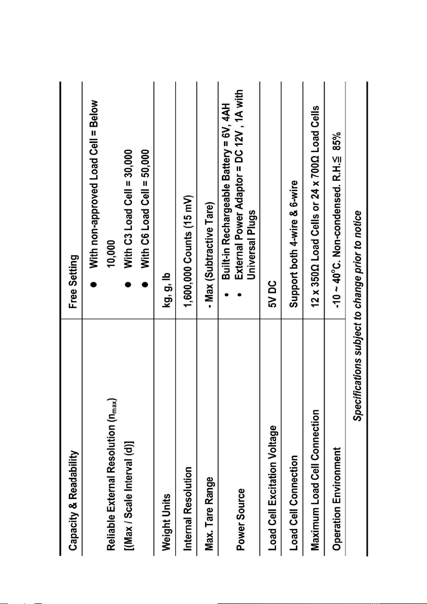
2. Specifications
7
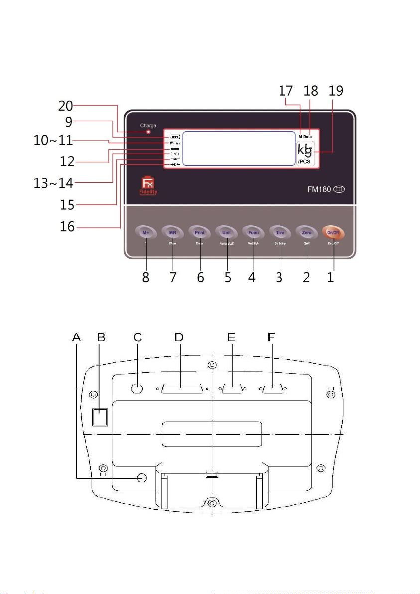
3. Keys, Display & Connections

8
1. On/Off Key
Press this key to turn this instrument on or off.
2. Zero Key
Press this key to set weight displayed to zero when an empty scale has
drifted away from a true zero reading.
3. Tare Key
Press this key to tare off the weight of a container.
4. Function Key
Press this key to shift between weighing, percentage and piece count
mode.
5. Unit Key
Press this key to shift among various weight units (if weight unit
conversation is enabled).
6. Print Key
1
Press this key to print the results to a computer or a printer through the
RS-232 output.
7. MR Key
Press this key to recall total stored transactions.
8. M+ Key
Press this key to accumulate current weight to memory manually.
9. Battery Power / Level Indicator
Visible to show: -
•This instrument is being powered by the built-in rechargeable
battery,
•Remaining battery level.
1
This key is also used to accumulate the current weight value to memory when internal
function F17 is set to ON.

9
10. W1 Indicator
2
(When under dual weighing range mode
3
) Visible when this instrument
is in the first weighing range (W1).
11. W2 Indicator
4
(When under dual weighing range mode) Visible when this instrument is
in the second weighing range (W2).
12. Minus Sign
Visible when a negative value is displayed.
13. Gross Indicator
Visible when gross weight reading is displayed.
14. Net Indicator
Visible when the tare function is in effect. Weight reading shown is net
value.
15. Stable Indicator
Visible when weight reading is stable.
16. Zero Indicator
Visible when instrument is at true zero weight status.
17. M+ Indicator
Visible when memory contains of accumulated data.
18. MR Indicator
Visible when the total accumulated weight value is displayed.
2
This indicator will not appear when this instrument is in single range mode.
3
This instrument can support two weighing ranges with different maximum capacities (Max)
and different scale intervals (d), each range extending from zero to its maximum capacity.
4
This indicator will not appear when this instrument is in single range mode.

10
19. Weight Units and Functions
•kg = kilogram,
•PCS = Pieces (Piece Count Mode in function),
•kg/PCS and g/PCS = Weight per piece (when Piece Count Mode in
function),
•lb = pound.
20. Charge Status Indicator
•Red color: Recharging battery,
•Green color: Charging completed
A. DC Jack Input for Indicator
External power adaptor is plugged in here.
Output requirements of the power adaptor: -
•DC9 ~ 12V 800mA,
•Polarity: - Any kind.
B. Blank
No Function
C. Load Cell Connector (7-Pin)
Signal from load cell (or junction box) is connected here.
D. Blank
No function
E. Blank
No function
F. RS232 (Serial) Comport
RS232 (Serial) communication comport.
Table of contents
Other Fidelity Electronics Accessories manuals


