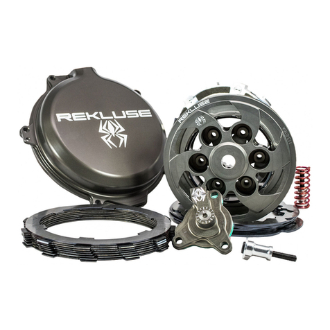
Rekluse Motor Sports RadiusCX Clutch Operation manual

©2017 Rekluse Motor Sports
Rekluse
Motor Sports, Inc.
customerservice@rekluse.com
I
NSTALLATION & USER’S GUIDE
RadiusCX Clutch
For KTM/Husqvarna CSS clutches
Doc ID: 191-7902A
Revision: 040919

Pg.
2 Doc ID: 191-7902A
Doc Rev: 040919
TABLE OF CONTENTS
OVERVIEW ............................................................................................... 3
INSTALLATION TIPS ................................................................................ 3
TOOLS NEEDED ...................................................................................... 4
INCLUDED PARTS ................................................................................... 5
DISASSEMBLE THE CLUTCH ................................................................. 6
INSTALL THE HUB ................................................................................... 8
CLUTCH PACK INSTALLATION............................................................... 9
PRESSURE PLATE INSTALLATION ...................................................... 14
SLAVE CYLINDER INSTALLATION ....................................................... 17
Step 1: Bleed the new slave cylinder ......................................... 17
Step 2: Replace OE slave cylinder ............................................ 20
BLEED THE CLUTCH LINE .................................................................... 24
SET THE INSTALLED GAP AND VERIFY BY CHECKING FREE PLAY
GAIN........................................................................................................ 27
Step 1: Find the starting point .................................................... 28
Step 2: Learn how to check Free Play Gain .............................. 29
Two Ways to Check for Free Play Gain..................................... 31
The Rubber Band Method ......................................................... 31
The Hand Method ...................................................................... 34
Step 3: Break-in the new clutch ................................................. 36
Step 4: Adjust the installed gap and Recheck Free Play Gain... 38
FREE PLAY GAIN ADJUSTMENTS ....................................................... 40
MAINTENANCE ...................................................................................... 41
Disk inspection examples .......................................................... 43
TROUBLESHOOTING ............................................................................ 44
Performance issues ................................................................... 44
Clutch noise ............................................................................... 44
EXP TUNING OPTIONS ......................................................................... 44
Changing the springs................................................................. 45
Configuration chart .................................................................... 47
BUMP-STARTING ................................................................................... 47
NEED ADDITIONAL HELP?.................................................................... 48
Doc ID: 191-7902A
Doc Rev: 040919
Pg. 3
This kit replaces many of the OE (Original Equipment) clutch parts
while reusing some of the OE clutch parts. The following is a
summary of what is replaced and what is reused:
·All OE steel drive plates will be replaced with Rekluse TEC
drive plates
·All OE friction disks will be replaced with Rekluse TorqDrive®
disks
·All 6 of the OE drive pins will be reinstalled
·The OE clutch cover O-ring will be reused
·Read the safety information sheet
included with your kit.
·Watch the “RadiusCX Auto Clutch Installation
Video” by visiting www.rekluse.com/support/videos.
·Protect eyes and skin –wear safety glasses and thin
disposable work gloves.
·Read this entire document before performing any steps.
·Lay the motorcycle on its left side when replacing the clutch.
This makes the clutch work easier and eliminates the need to
drain the oil.
·Use an air or electric impact wrench to remove the center
clutch nut. If one is not available, you can place the bike in top
gear and hold the rear brake while loosening the center clutch
nut with a socket and breaker bar.
·Channel-lock pliers work best to bend the tabs of the washer
up over the center clutch nut.
·For optimal clutch performance Rekluse recommends using
fresh, clean oil that meets JASO-MA oil rating requirements.
Rekluse offers Factory Formulated Oil™ developed specifically
for Rekluse products. Rekluse Factory Formulated Oil is a
perfect complement to any OEM or aftermarket wet clutch. Visit
www.rekluse.com to learn more.
OVERVIEW
INSTALLATION TIPS

Pg.
4 Doc ID: 191-7902A
Doc Rev: 040919
·Bikes with taller gearing or modified engines with increased
horsepower may require heavier wedges. These can be
purchased separately from Rekluse.
4 mm Allen Wrench
5 mm Allen Wrench
8 mm Socket
27
mm Socket
Torque Wrench
Channel
-
lock Pliers
Fluid Catch Container
No Tools
Required
Recommended
Clutch Fluid
Calipers
TOOLS NEEDED
4mm
5 mm
8 mm
27 mm

Doc ID: 191-7902A
Doc Rev: 040919
Pg. 5
*depending on bike model
Visit www.rekluse.com/support for a full parts fiche illustration and part numbers.
INCLUDED PARTS
Item
Description
Qty.
5
Pressure Plate
1
13
EXP Bases
2
16
Steel Lining Plate
1
23
Clutch Cover
1
27
Center Hub
1
30
Lock Tab Washer
1
51
Fastener - 1/4-Turn Pin
6
60.X
EXP Adjustment Spring (extra adjustment
springs are included, see last page for EXP
tuning options)
6
63
Steel Drive Plate
8 or 9*
69
TorqDrive®Friction
7 or 8*
85
Wedge Assembly
6
86
Adjustable Slave Cylinder Assembly (bleed
syringe included)
1
88
Spring Kit
1

Pg.
6 Doc ID: 191-7902A
Doc Rev: 040919
1. Turn the fuel petcock to “OFF” if applicable.
2. Lay the bike on its left side. Catch any fuel that might drain
in a suitable container.
3. Use an 8 mm socket to remove the clutch cover.
DISASSEMBLE THE CLUTCH
8 mm

Doc ID: 191-7902A
Doc Rev: 040919
Pg. 7
4. Use an 8 mm socket to remove the following OE parts.
See following picture for reference.
·6 pressure plate bolts and
springs
·Pressure plate
·Throw-out bearing and
washer
·Center clutch nut and washer
·
12
drive pins
·
Clutch pack
·
Center clutch hub
Be careful that the drive pins do not fall into the engine while
disassembling.
8 mm

Pg.
8 Doc ID: 191-7902A
Doc Rev: 040919
5.Use a hammer and large screwdriver to bend down the
tabs of the washer tab, then remove the center clutch
nut with an impact wrench or breaker bar, and a 27 mm
socket.
6.Remove the tab washer, then remove the hub.
1. Install the new Rekluse center clutch hub into the bike. Check to
make sure the thrust washer is still on the main shaft before you
install the hub.
2. Reinstall the Rekluse tab washer and OE center clutch nut.
3. Using the 27 mm socket and torque wrench,
torque the center clutch nut to 50 ft-lbs (68 N-m).
INSTALL THE HUB
27 mm
27 mm
Torque Wrench

Doc ID: 191-7902A
Doc Rev: 040919
Pg. 9
4. Bend up both tabs of the tab washer using channel-lock pliers.
5. Seat the 6 OE drive pins into the Rekluse outer hub.
Each clutch pack comes with a set of steel plates, a set of friction
disks, and an EXP disk. The specifics of the clutch pack depend on
the bike. The height of the assembled clutch pack and specific
information for each bike can be found on the Setup Sheet.
CLUTCH PACK INSTALLATION
Channel-lock
Pliers

Pg.
10 Doc ID: 191-7902A
Doc Rev: 040919
1. Soak the friction disks and EXP disk in new oil for at
least 5 minutes. Make sure the EXP and friction disks
are coated on both sides.
2. Install a steel drive plate first. Hold a TEC drive plate so that
the “shark fin” notches face toward the right. All the drive
plates will follow this orientation.
Proper orientation of the drive plates is critical for optimal clutch
performance. If you install them backwards the clutch will still
function but will lack proper modulation performance.
Oil
Face the “shark
fin” to the right.

Doc ID: 191-7902A
Doc Rev: 040919
Pg. 11
3. Align the drive pin notches in the TEC drive plate with the
drive pins on the hub, then install the drive plate into the
basket. Be sure that the drive pins are seated in the notches
and not in the bigger sections.
ALL the TEC plates must be aligned in the drive pins notches or
damage may occur. The plates will not move when installed
correctly.

Pg.
12 Doc ID: 191-7902A
Doc Rev: 040919
4. On top of the steel drive plate, install a Rekluse friction disk.
Continue to alternate steel drive plates and friction disks for
the entire clutch pack. Some friction disks are marked with a
small colored dot. This mark is used for processing and can be
ignored.
5. Install the EXP disk on top of the last steel drive plate. Make
sure the EXP disk is seated in the main slots along with the
clutch pack.
*Refer to the Setup Sheet included with the clutch
kit for the “Clutch Pack Height” specifications.

Doc ID: 191-7902A
Doc Rev: 040919
Pg. 13
Some OE basket have “half slots” at the top of the basket tangs.
Rekluse products require that the entire clutch pack, including the
EXP disk, be installed into the MAIN (deeper) basket slots.
6. Reinstall the OE throw-out.

Pg.
14 Doc ID: 191-7902A
Doc Rev: 040919
1. Add a light film of oil between the lining plate and
pressure plate. This will help the plates stick together for
ease of installation.
2. Install the supplied lining plate onto the Rekluse pressure plate
by lining up the index tabs into the slots.
3. Install the pressure plate subassembly.
PRESSURE PLATE INSTALLATION
Oil
No Tools
Required

Doc ID: 191-7902A
Doc Rev: 040919
Pg. 15
4. Place the pressure plate springs into the assembled clutch, then
insert the screw sleeves into the springs.
5. Insert the pressure plate bolts into the screw sleeves.
Do not reuse the OE springs, or clutch cover interference will
occur!
6. Using a torque wrench, tighten the pressure plate
bolts to 9 ft-lb (12-N-m).
Torque Wrench

Pg.
16 Doc ID: 191-7902A
Doc Rev: 040919
7. Install the OE cover gasket onto the Rekluse clutch
cover.
8. Install the Rekluse clutch cover by lightly tightening
the cover bolts in a star pattern. Tighten bolts in
small increments before torquing the cover bolts to
OE specifications. If your bike has an oil plug, transfer
the OE oil plug to the new Rekluse clutch cover.
Torque Wrench

Doc ID: 191-7902A
Doc Rev: 040919
Pg. 17
Installing the new Rekluse slave cylinder takes several steps. Please
read the entire section before beginning the process to ensure you
have the right equipment and clutch fluid needed for the
replacement. Rekluse recommends wearing gloves and safety
glasses for the install.
During the bleed and assembly, note that there is a small ball
bearing installed in the slave piston with a small amount of
grease. When installing the Rekluse slave cylinder, make sure
the ball is in place and has not come loose.
Step 1: Bleed the new slave cylinder
This step prepares the new slave cylinder for installation. Bleed the
cylinder on a workbench or an area away from the bike.
1. Using a 4 mm Allen wrench, turn the adjuster screw
counterclockwise so that the top O-ring is visible under
the adjuster screw.
SLAVE CYLINDER INSTALLATION
4 mm

Pg.
18 Doc ID: 191-7902A
Doc Rev: 040919
2. Use your thumbs to compress the piston until it bottoms out, then
release it.
3. Pour the recommended clutch fluid into the slave
cylinder port.
Be sure to use the correct clutch fluid. Check the cap of the
clutch master cylinder to determine which clutch fluid to use.
Failure to use the correct fluid will result in seal damage
and/or failure.
4. Use a 4 mm Allen wrench to turn the adjuster screw
clockwise until it bottoms out and the O-ring in no
longer visible. Keep the fluid topped off as you go.
4 mm

Doc ID: 191-7902A
Doc Rev: 040919
Pg. 19
5. Use the wrench to turn the adjuster screw counterclockwise back
to the initial position, with the top O-ring visible. Keep the fluid
topped off as you go.
6. Use your thumbs to compress the piston again until it bottoms
out while looking for air bubbles.
When compressing the piston, fluid can shoot out from the
slave cylinder port. Be sure to wear eye protection.
7. Repeat steps 3 - 6 until there are no air bubbles coming out in
the fluid when the piston is compressed.
8. When the bleeding is complete, turn the adjuster screw
counterclockwise so that the top O-ring is visible.
9. Compress the piston until it bottoms out, and top off with fluid.

Pg.
20 Doc ID: 191-7902A
Doc Rev: 040919
10.Check that the ball bearing is still in place. Stand the Rekluse
slave cylinder in an upright position (so that the fluid does not
spill) until it is needed in the next step.
Step 2: Replace OE slave cylinder
In this step, the OE slave cylinder is replaced with the Rekluse
slave cylinder. Work quickly when performing the following steps.
This method retains the fluid inside the line, and makes the final
bleeding step easier.
1. Stand the bike up and lean it on its kickstand, or place it on a
suitable bike stand.
If you are installing on a 350 Freeride bike model, see the Slave
Cylinder Appendix sheet for proper install instructions.
2014-2017 250 Freeride owners: Insert bleeder bolt into Rekluse
slave cylinder in the same orientation as the OE slave cylinder.
Table of contents
Other Rekluse Motor Sports Motorcycle Accessories manuals

Rekluse Motor Sports
Rekluse Motor Sports Radius CX Clutch User manual

Rekluse Motor Sports
Rekluse Motor Sports Core Manual User manual

Rekluse Motor Sports
Rekluse Motor Sports EXP Operation manual

Rekluse Motor Sports
Rekluse Motor Sports EXP User manual

Rekluse Motor Sports
Rekluse Motor Sports Core EXP 3.0 Operation manual
Popular Motorcycle Accessories manuals by other brands

Tucano Urbano
Tucano Urbano TERMOSCUD-R204X instruction manual

hepco & becker
hepco & becker 6547557 01 01 manual

Sharper Image
Sharper Image 206621 user guide

R&G
R&G ADVENTURE BARS Fitting instructions

hepco & becker
hepco & becker 6304522 black Assembling instructions

hepco & becker
hepco & becker 501984 00 01 manual