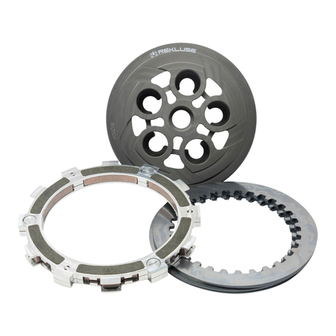
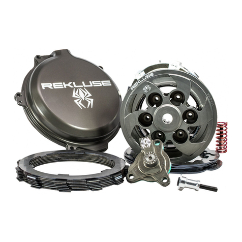
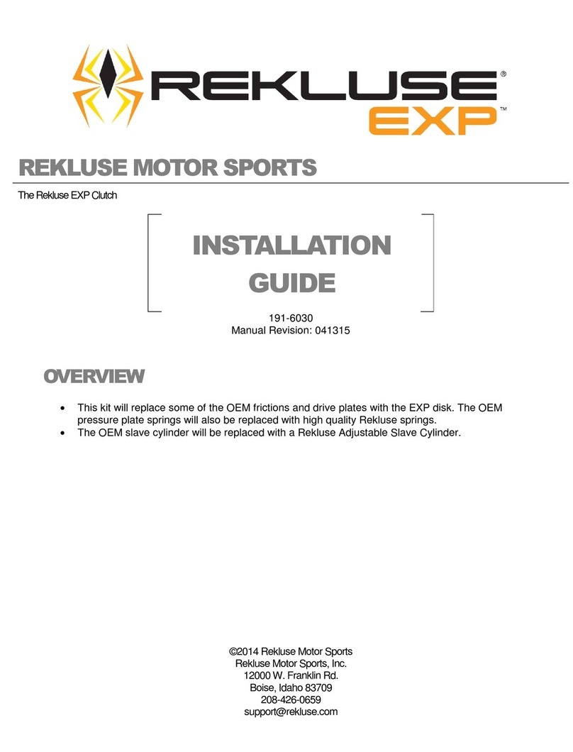
Rekluse Motor Sports EXP Operation manual

©2016Rekluse Motor Sports
Rekluse Motor Sports, Inc.
208-426-0659
customerservice@rekluse.com
REKLUSE MOTOR SPORTS
The Rekluse Core EXP Kit with Adjustable Slave Cylinder
INSTALLATION &
USER’S GUIDE
Doc ID: 191-7709A
Doc Rev: 091217
OVERVIEW
•This kit replaces the OEM core clutch components including the center clutch hub and pressure
plate with high-quality billet components designed for optimal operation specific to your bike.
•Most of the OEM friction disks will be reused, but all OEM steel drive plates will be replaced with
Rekluse drive plates.

Rekluse Core EXP - Hydraulic Page 2
INSIDE THIS DOCUMENT
oINSTALLATION
oSETTING THE INSTALLED GAP
oCHECKING FREE PLAY GAIN
oBREAK-IN
oMAINTENANCE
oEXP TUNING OPTIONS & ENGAGEMENT SETTINGS
oSLAVE CYLINDER APPENDIX (only some models)
oTROUBLESHOOTING GUIDE
INSTALLATION TIPS
•Watch the “CORE EXP Auto-Clutch Installation Video”by following this QR
code or visiting rekluse.com/videos.
•Read this entire document before performing any steps, so you will know what to expect.
•Be sure to use proper eye protection.
•Laying the bike on its left side makes clutch work easier and eliminates the need to drain the oil.
•An air or electric impact wrench works well to remove the center clutch nut, or you can place the
bike in top gear and hold the rear brake while loosening the center clutch nut with a socket.
•Channel-lock pliers work best to bend the tabs of the washer up over the center clutch nut.
•Use clean, quality JASO MA certified transmission oil for best performance.
•Bikes with taller gearing or modified engines with increased horsepower may require heavier
wedges and/or stiffer pressure plate springs which can be purchased separately from Rekluse.
TOOLS NEEDED
•8mm socket
•27mm socket (most models)
•8mm & 12mm end wrenches
•4mm & 5mm Allen keys
•Torque wrench (in-lb & ft-lb, or N-m)
•Channel-lock pliers
•Hydraulic clutch fluid

Rekluse Core EXP - Hydraulic Page 3
INCLUDED PARTS
Item Item Type Qty
5
Pressure Plate
1
8
Pressure Plate Plug
1
13
EXP Base *
2
16
Steel Lining Plate
1
23
Clutch Cover
1
27
Center Clutch Hub
1
30
Lock-Tab Washer
1
31
Screw Sleeve
6
47
Fastener – M6 Screw (requires 5mm Allen tool)
6
51
Fastener - 1/4-Turn Pin *
6
60
EXP Adjustment Spring * (extra included, see last page for tuning options)
6
60.1,2
Pressure Plate Spring (some models come with 2 different colors of springs)
6
67
Steel Drive Plate – Thick (.060” [1.5mm])
6
67.1
Steel Drive Plate – Thin (.040” [1.0mm])
1
85
Wedge Assembly *
6
86
Adjustable Slave Cylinder Assembly (bleeder bolt included)
1
87
Throwout Assembly (only certain models)
1
88
Core Clutch Spring Kit Assembly
1
* Denotes parts assembled as a component of the EXP disk assembly
Picture above is representative. See the parts list included with the product or visit
Rekluse.com/support for a full parts fiche illustration and part numbers.

Rekluse Core EXP - Hydraulic Page 4
PREP & DISASSEMBLY
1. Lay the bike on its left side. Catch any fuel that
might drain in a suitable container. Remove the
clutch cover.
2. Remove the OEM clutch parts named in the
following diagram. Leave the basket installed.
3. Separate the OEM clutch pack.
Inspect the friction disks for signs of heat or
wear. Replace if they are burnt or worn.For
most models, new friction disks can be
purchased from Rekluse.
4. Inspect the basket for cushion slop or notching.
If notched or worn, it is recommended to install
a Rekluse Billet Clutch Basket (available for
most models).
5. Soak the EXP disk in engine oil for 5 min.

Rekluse Core EXP - Hydraulic Page 5
HUB & CLUTCH PACK
INSTALLATION
6. Install the new center clutch hub on top of the
OEM thrust washer.
NOTE: Rekluse has determined that some models
have slight variance between the center hub and
the main shaft. If your Rekluse center hub seems to
be too tight to fit on the main shaft please follow
these steps:
1. Pre-heat your oven to 200°F (94°C).
2. Using appropriate hot part handling protective
gear, place your center hub in the oven for 10
minutes.
3. Using appropriate hot part handling protective
gear, remove the center hub from the oven and
immediately install on to main shaft.
4. Wait until the center hub has completely cooled.
5. Resume installation at step 6.
This installation process will ensure appropriate
center hub fitment.
7. Torque the nut to 50 ft-lb (70 N-m). Bend both
tabs of the lock washer up.DO NOT OVER
TORQUE, or the clutch will drag and damage
may occur.
8. Install the new clutch pack.
NOTE: The first plate installed is the 0.040”
Rekluse Steel Plate. Proceed to install the rest
of the clutch pack alternating frictions (6x) and
remaining drive plates (6x).
NOTE: Some OEM Baskets have “half-slots” at
the top of the basket tangs. Rekluse products
require that all friction disks, including EXP
disk, are seated into the MAIN (deeper)
basket slots.
Rekluse Core EXP - Hydraulic Page 6
9. Install the included Rekluse throw-out
assembly in the order shown in the following
diagram on top of the stock throw-out rod.
NOTE: If you are missing the top washer, it is
probably stuck to the backside of your OEM
pressure plate.
PRESSURE PLATE
INSTALLATION
10. Place the Lining Plate [#16] onto the Rekluse
Pressure Plate [#5].Adding an oil film between
them will help them stick together for ease of
installation.
11. Install this pressure plate subassembly.
12. Install the pressure plate springs.
Model-Specific Spring Notes:
Beta 250/300cc 2-strokes only:
Your product includes a bi-colored 6-spring kit,
containing 3 of each color: Alternate spring
colors clockwise when installing them to ensure
even clamping force on the pressure plate.
CLUTCH COVER
13. Your new Core EXP clutch is taller than the
OEM clutch, so the Rekluse Clutch Cover has
been designed for clearance with all moving
parts. You must use the Rekluse Clutch Cover
or interference and clutch damage will occur.

Rekluse Core EXP - Hydraulic Page 7
SLAVE CYLINDER
INSTALLATION
Handle with care! During assembly there is a small
ball bearing [#56] installed in the slave piston
[#28.3] with a small amount of grease. When
installing the Rekluse slave cylinder, make sure the
ball does not come loose.
14. Stand the bike up and lean it on its kickstand or
place it on a suitable bike stand.
15. On a workbench (away from the engine), bleed
the Rekluse slave cylinder by this procedure:
a. Use a 4mm Allen key to make the top O-
Ring [#53.1] visible on the adjuster screw
[#28.2].
b. Compress the piston [#28.3] until it bottoms.
c. Pour clutch fluid into the slave cylinder port.
WARNING
Be sure to use the correct clutch fluid! Check the
cap of the clutch master cylinder to determine
which clutch fluid to use. Failure to use the correct
fluid will result in seal damage and/or failure.
d. Turn the adjuster screw clockwise until it
bottoms, keeping the fluid topped off.
e. Turn the adjuster screw back to the initial
position with the top O-ring visible.

Rekluse Core EXP - Hydraulic Page 8
f. Compress the piston until it bottoms out.
Repeat the process until there is no longer
air escaping from the top port when the
piston is compressed.
NOTE: When compressing the piston, fluid
can shoot out from the slave cylinder port. Be
sure to wear eye protection.
16. Check that the ball bearing [#56] is still in place.
NOTE: The Rekluse slave cylinder comes
preassembled in the kit. If the parts become
separated, assemble them in the following order:
Rekluse slave cylinder, O-ring, then the supplied
paper gasket.
17. At the slave cylinder, remove the OE banjo bolt
and fluid line from the stock slave cylinder. You
can leave the bleeder bolt in the stock slave
cylinder, since a new one is provided with the
Rekluse slave cylinder assembly.
18. Attach the clutch fluid line to the Rekluse slave
cylinder using the OE banjo bolt and the 2 new
crush washers from Rekluse. Make sure the
banjo fitting is between the 2 crush washers.
19. Tighten the banjo bolt with your hand until
snug. (You will torque it to spec once installed
on the bike.)
OE Banjo Bolt
OE Crush
Washers
OE Banjo
Rekluse Crush
Washers
Rekluse
Bleeder

Rekluse Core EXP - Hydraulic Page 9
NOTE: Some models have a piston
diaphragm seal on the stock slave cylinder.
DO NOT REUSE this seal if OE equipped.
20. With the clutch fluid line attached to the
Rekluse slave cylinder, remove the OE slave
cylinder from the engine. Keep the OE bolts for
reuse.
21. Mount the Rekluse slave cylinder to the engine
by lightly threading the two shorter OE bolts on
the left side until finger tight.
22. Remove the OE chain guard screw sleeve
from the plastic chain guard by gently pushing
it out the backside.
23. Insert the new Rekluse chain guard screw
sleeve into the screw slot.
24. Reattach the chain guard to the slave cylinder
using the longer OE screw.

Rekluse Core EXP - Hydraulic Page 10
NOTE: The Rekluse screw sleeve is slightly taller
than the OE screw sleeve. You will need to use the
Rekluse screw sleeve to help ensure a good seal to
the engine case.
25. Tighten all the slave cylinder screws to OE
specifications.
26. Torque the banjo bolt to 18 ft-lb (25 N-m) per
OE specification.
27. Optional: If you purchased the Rekluse Slave
Guard accessory (available for most models),
install it now using the instructions in the kit.
28. Remove the cap and bladder from the clutch
master cylinder and top off the clutch fluid.
29. Attach the supplied bleed tube to the bleeder
bolt port and loop it into a suitable catch bottle.
30. Pump the clutch lever 3-5 times then hold it
against the bar/grip.
31. Using an 8mm wrench, open the bleed port. Air
and fluid should come out of the bleed tube.
Tighten the bleed port.

Rekluse Core EXP - Hydraulic Page 11
32. Slowly release the clutch lever and check the
fluid level in the clutch master cylinder.
33. Repeat the previous 3 bleeding steps until air
no longer comes out of the bleed port. Then,
check that the clutch lever functions properly.
Repeat the bleeding procedure if necessary.
34. Remove the bleed tube and bottle, then torque
the bleed screw to 150 in-lb (17 Nm).
INSTALLED GAP SETTING
DEFINITION:“Installed Gap” is the separation in
the clutch pack created by the adjustment of the
Adjuster Screw in the Slave Cylinder. This gap is
what allows the clutch to spin freely until the
desired RPM is reached for engagement; it must be
set correctly for optimal performance.
35. Using the long end of a 4mm Allen key, turn the
adjuster screw clockwise until it stops under
moderate pressure. You are trying to feel for
the point at which the throw-out will start to lift
the pressure plate. This is the “starting point”.
NOTE: It may take a few tries to find the point
at which the system is bottomed out. You
should feel a distinguishable change in turning
effort at this point.
36. Once you have found the starting point, turn the
adjuster clockwise 1 full turn plus 5 marks
(or “1+5”). This is NOT your final setting, but
it is a good reference point for using free play
gain to find the correct setting.
37. Top off the master cylinder with clutch fluid and
reinstall the OEM cap and bladder.

Rekluse Core EXP - Hydraulic Page 12
CHECKING LEVER
FREE PLAY GAIN
WARNING
Always make sure that the bike is in NEUTRAL before
checking Free Play Gain. Failure to do so may result in
the bike lurching forward, and loss of control and/or
injury may result.
NOTE: Before performing this step,
please visit our website at
rekluse.com/support to view the
TECH VIDEO entitled “How to Check
Free Play Gain”.
“Lever Free Play”is essentially the “slack” in the
clutch lever before it starts actuating the clutch.
Applying a light finger pressure will take up this
slack.
“Free Play Gain” is the increase of lever free play
as the auto-clutch engages. This happens when
the RPM increase from idle through around 5,000
RPM. Free Play Gain is caused by the expansion of
the EXP disk which lifts the pressure plate away
from the throwout assembly.
Optimal Free Play Gain yields 1/8” (3mm) of clutch
lever movement, measured at the end of the lever.
This measurement at the lever correlates to
achieving the ideal installed gap.
The following steps explain two ways to check Free
Play Gain. One will use the rubber band that has
been included in the clutch kit and one explains
using your hand, which you will perform before
every ride.
Place the bike in neutral, start the engine and let it
warm up for 2-3 minutes.
Rubber Band Method:
It is recommended that you use this method first
to find your Free Play Gain so you can see what
it is. Then, check it by hand as well so that you
can effectively and comfortably check free play
gain every time you ride.
Wrap the included rubber band around the outer
end of the handlebar grip and attach it to the ball
end of the clutch lever.

Rekluse Core EXP - Hydraulic Page 13
With the bike at idle in neutral, quickly blip (rev)
the engine to at least 5,000 RPM and let it
return to idle. The clutch lever should move
in about 1/8” (3mm) toward the handlebar as
you rev the engine.
Note: If you are not getting the correct lever
movement, see the “Free Play Gain
Troubleshooting Guide” on the next page.
Hand Method:
Free play gain should also be checked using
your hand, as you will check it by hand before
every ride. With the bike at idle, apply enough
pressure to the lever to take up the initial
freeplay (slack) shown in the photos on the
previous page. While continuing to apply light
pressure, rev the engine to at least 5,000 RPM.
The clutch lever should move in 1/8” (3mm)
under your finger pressure as you rev the
engine and the auto-clutch engages.

Rekluse Core EXP - Hydraulic Page 14
BREAK –IN
Follow these procedures for a new installation and
any time new friction disks or EXP bases or wedges
are installed.
1. Rev cycles: Warm up the bike for 2-3 minutes.
With the bike in neutral and your hand off of the
clutch lever, rev the engine 10 times, being sure
to let it return to idle between each rev cycle.
2. With the engine running, pull in the clutch lever
and click the bike into gear. Slowly release the
clutch lever. The bike should stay in place,
perhaps with a slight amount of forward creep.
3. Now that the bike is idling in first gear, slowly
apply throttle to begin moving. To break in the
clutch components, perform the following roll-on
starts in 1st and 2nd gear without using the
clutch lever: In 1st gear, accelerate moderately
to approximately 5,000 RPMs and come to a
stop—repeat this 5 times. Next, starting in 2nd
gear, accelerate moderately to approximately
5,000 RPMs then come to a stop—repeat this 5
times.
4. Now that the EXP is broken-in and the clutch is
warm, re-check free play gain at your clutch
lever and adjust if necessary. Your clutch pack
will expand with heat, so final adjustments
should be made when the bike is warm. Now
you are ready to ride!
WARNING:DO NOT RIDE WITHOUT
SUFFICIENT FREE PLAY GAIN!
Checking free play gain is easy and takes less than
a minute to perform. For optimum performance
and longevity, check free play gain when the bike is
warm at the start of every ride.
FREE PLAY GAIN
TROUBLESHOOTING
Each adjustment should be done in small
increments - one tick mark at a time. After each
adjustment, repeat the rev-cycle until optimal free
play gain is achieved.
Symptom:
- Clutch lever moves in too far (too much free
play gain)
- Clutch has excessive drag
- It is difficult to fully override the clutch with
the lever
Answer: Installed Gap is too small
Solution: Turn the Adjuster Screw inwardly
(clockwise) to increase the Installed Gap.
Symptom:
- Clutch lever does not move enough or does
not move at all (too little free play gain)
- Clutch is slipping
Answer: Installed Gap is too large
Solution: Turn the Adjuster Screw outwardly
(counter-clockwise) to reduce the Installed Gap. It
may be helpful to re-find the starting point.

Rekluse Core EXP - Hydraulic Page 15
CLUTCH NOISE
Although it is harmless, some bike models may
have “squeal” or “chatter” coming from the clutch at
low RPM as it engages. Clutch squeal is caused by
the clutch components vibrating as the clutch
engages and can become more audible as the
clutch gets hot. For bike models that tend to have
clutch squeal or chatter here are some
recommendations to reduce or eliminate it:
- Oil: Rekluse recommends that you have fresh,
clean JASO-MA rated oil for best clutch
performance. Dirty or old oil can make the
clutch more likely to squeal or chatter. Some
heavy-duty oil stabilizers or other additives
have been known to reduce noise and make
shifting smoother. Be sure that any additives
you might use are approved for use in wet-
clutch motorcycles.
- Clutch Basket: Available for some models, a
Rekluse Clutch Basket will eliminate clutch
squeal and chatter in most cases because it is
precision machined from high quality material
and includes long-life clutch dampers. A clutch
basket that is damaged or has worn-out
dampers tends to increase clutch noise.
- Installed Gap: Adjusting the Installed Gap will
NOT affect clutch squeal or chatter
MAINTENANCE
- Maintain adequate free play gain, checking
before every ride and adjusting if necessary.
- Keep up with regular oil changes as per the
bike manufacturer’s recommendations. Clutch
function and longevity depends on oil quality.
- Inspect all of your clutch parts every 40 hours
for signs of wear or excessive heat, and replace
components as necessary.
- Repeat the break-in procedure anytime the
friction disks or EXP bases or wedges are
replaced.Always soak friction disks or EXP
bases in oil for at least 5 minutes before
installing.

Rekluse Core EXP - Hydraulic Page 16
EXP TUNING OPTIONS
Included are spring options to tune the engagement RPM of the EXP disk. The EXP disk comes set with the
recommended “Medium” setting from Rekluse. See chart on next page for setting options.
Adjusting the engine idle speed to match your engagement setting is important and greatly affects the overall
feel of how the EXP disk engages. To prevent freewheeling and maximize engine braking, set the idle so there
is a slight amount of drag while the bike is idling in gear and warmed up. The idle should not be so high as to
move the bike forward in gear with the throttle closed. However, with a small opening of the throttle the bike
should move forward.
It is NOT necessary to disassemble the EXP halves to change springs! To change springs, remove 3 of the
¼-turn pins from one side of the EXP, replace springs, and re-install ¼-turn pins. Next, flip the EXP disk over
and repeat on the other side if necessary. To maintain even pressure when using two different color spring
sets, install one color set of 3 on one side of the EXP and the remaining color set of 3 on the other side.
CAUTION:If you disassemble the EXP, bearing pads may fall out or be stuck to the ramp surfaces of the
EXP bases.Take care to ensure all pads are correctly placed into wedge pockets using gentle pressure to
avoid damage to the pad surfaces before reassembling the EXP. Properly seated pads will be secured in
place once the EXP is reassembled. Operating the clutch without the pads in place will cause part damage
or failure.

©2016 Rekluse Motor Sports
Rekluse Motor Sports, Inc.
208-426-0659
customerservice@rekluse.com
EXP ENGAGEMENT SETTINGS BY PRODUCT
Product
Make
Bike Model
Low Springs
Medium
Springs
High Springs
RMS-7721
Beta
250/300
6 Red
3 Red 3 Blue
6 Blue
RMS-7723
Beta
350/400/450/498/520
6 Red
3 Red 3 Blue
6 Blue
Other manuals for EXP
2
This manual suits for next models
2
Table of contents
Other Rekluse Motor Sports Motorcycle Accessories manuals

Rekluse Motor Sports
Rekluse Motor Sports Core Manual User manual

Rekluse Motor Sports
Rekluse Motor Sports RadiusCX Clutch Operation manual

Rekluse Motor Sports
Rekluse Motor Sports EXP User manual

Rekluse Motor Sports
Rekluse Motor Sports Core EXP 3.0 Operation manual

Rekluse Motor Sports
Rekluse Motor Sports Radius CX Clutch User manual