Rekluse RadiusCX Clutch Upgrade Kit Operation manual

©2017 Rekluse Motor Sports
Rekluse Motor Sports, Inc.
support@rekluse.com
INSTALLATION & USER’S GUIDE
RadiusCX Clutch Upgrade Kit
For KTM/Husqvarna DDS clutches
Doc ID: 191-7911A
Revision: 080420

Pg.
2 Doc ID: 191-7911A
Doc Rev: 080420
TABLE OF CONTENTS
OVERVIEW..................................................................................... 3
INSTALLATION TIPS...................................................................... 3
Tuning Note.................................................................................. 4
TOOLS ............................................................................................ 4
INCLUDED PARTS ......................................................................... 5
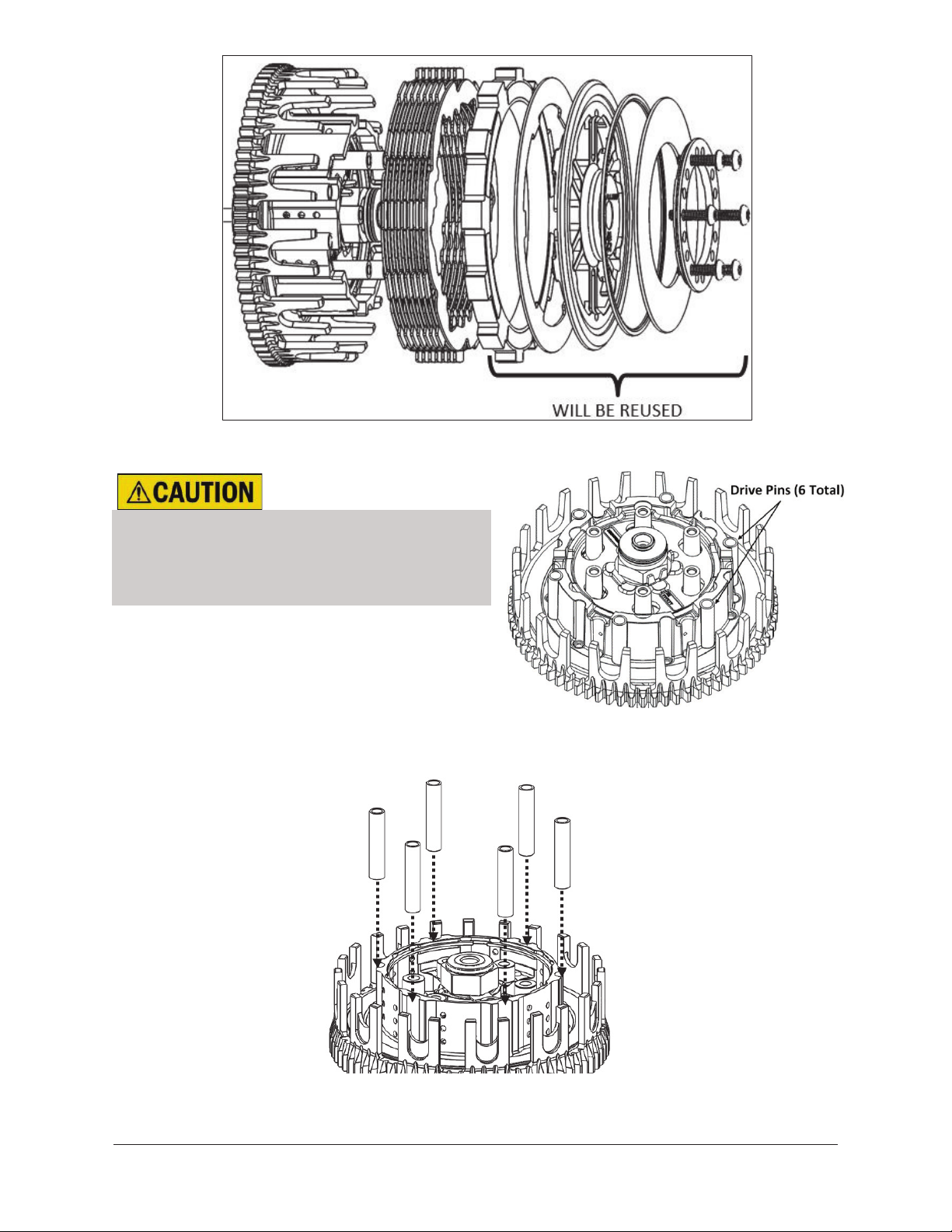
DISASSEMBLE THE CLUTCH ....................................................... 6
INSPECT THE DAMPERS.............................................................. 8
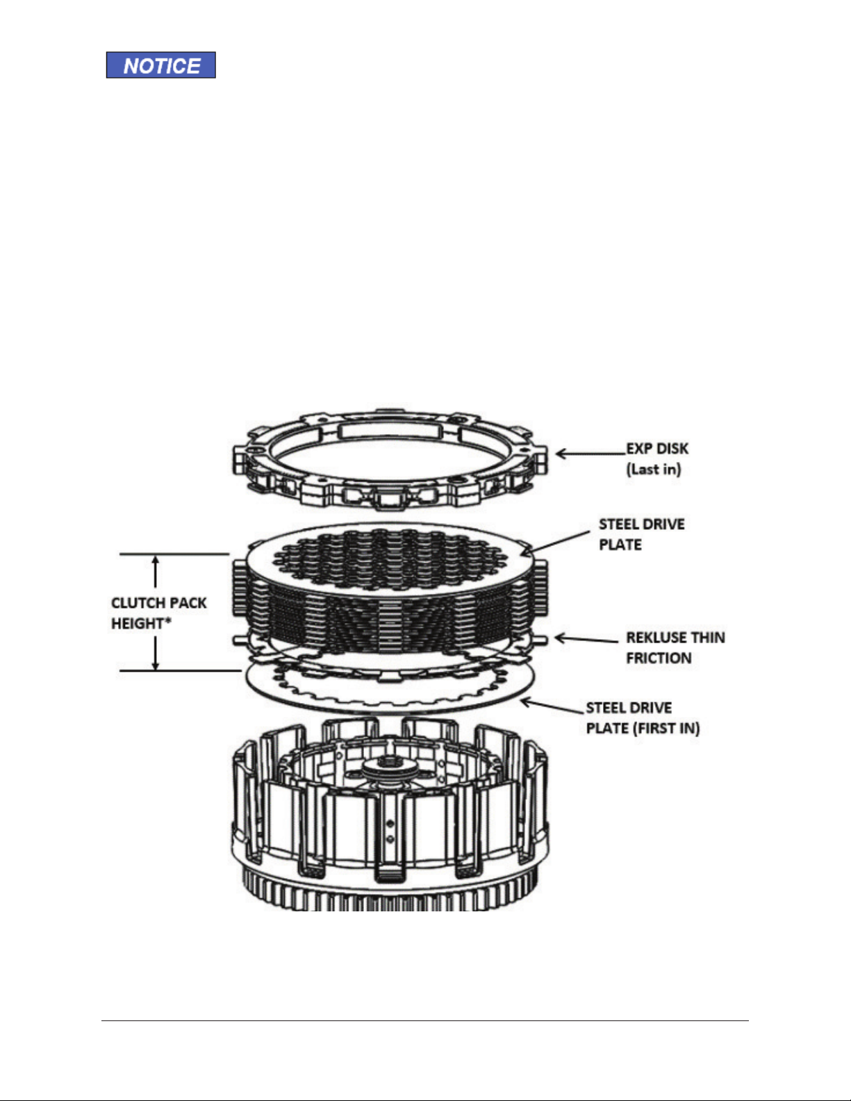
CLUTCH PACK INSTALLATION..................................................... 8
PRESSURE PLATE INSTALLATION............................................ 11
SET THE INSTALLED GAP AND VERIFY BY CHECKING FREE
PLAY GAIN ................................................................................... 15
Step 1: Find the starting point..................................................... 16
Step 2: Learn how to check Free Play Gain ............................... 17
Two Ways to Check for Free Play Gain ..................................... 19
The Rubber Band Method .......................................................... 19
The Hand Method....................................................................... 22
Step 3: Break-in the new clutch.................................................. 24
Step 4: Adjust the installed gap and Recheck Free Play Gain ... 26
FREE PLAY GAIN ADJUSTMENTS ............................................. 28
MAINTENANCE ............................................................................ 29
Disk inspection examples........................................................... 31
TROUBLESHOOTING .................................................................. 32
Performance issues.................................................................... 32
Clutch noise................................................................................ 32
EXP TUNING OPTIONS ............................................................... 32
Changing the springs ................................................................. 33
Configuration chart ..................................................................... 35
BUMP-STARTING THE BIKE ....................................................... 35
NEED ADDITIONAL HELP? ......................................................... 36

Doc ID: 191-7911A
Doc Rev: 080420
Pg. 3
OVERVIEW
This guide shows you how to replace your OE (Original Equipment)
core clutch parts with your new Rekluse upgraded clutch parts. The
following parts are replaced:
·Core EXP 3.0 Drive Plates
·OE Friction Disks
INSTALLATION TIPS
Read the safety information sheet
included with your kit.
·Protect eyes and skin –wear safety
glasses and thin disposable work gloves.
·Read this entire document before performing any steps.
·Lay the bike on its left side when replacing the clutch. This
makes the clutch work easier and eliminates the need to drain
the oil.
·For optimal clutch performance Rekluse recommends using
fresh, clean oil that meets JASO-MA oil rating requirements.
Rekluse offers Factory Formulated Oil™ developed specifically
for Rekluse products. Rekluse Factory Formulated Oil is a
perfect complement to any OEM or aftermarket wet clutch. Visit
www.rekluse.com to learn more.
·Bikes with taller gearing or modified engines with increased
horsepower may require heavier wedges. These can be
purchased separately from Rekluse.

Pg.
4 Doc ID: 191-7911A
Doc Rev: 080420
Tuning Note: (especially for 2-stroke owners):
·Once installed, if you desire your clutch to engage more
aggressively, one option is to purchase the heavier Belleville
spring from KTM (KTM calls it the “280” spring).
·Replacing this spring makes the clutch engagement more
aggressive. However, this will increase the pull on the clutch
lever. The spring comes stock on 2013 and newer Factory
Edition 450SX-F bikes, 2014 and newer 450SX-F/XC-F bikes,
2017 and newer 450/500 EXC-F bikes.
·The part number is KTM Part #: 78932005000
TOOLS
4 mm
Allen Wrench
8
mm Socket
Torque Wrench
T-25 Torx
Bit
Oil
Calipers
Fluid Catch
Container
8 mm
4 mm
Oil

Doc ID: 191-7911A
Doc Rev: 080420
Pg. 5
INCLUDED PARTS
Visit www.rekluse.com/support for
a full parts fiche illustration and part numbers.
Item
Description
Qty.
63
TEC Steel Drive Plate
9
69
TorqDrive
®
Friction
8

Pg.
6 Doc ID: 191-7911A
Doc Rev: 080420
DISASSEMBLE THE CLUTCH
1. Turn the fuel petcock to “OFF” if applicable.
2. Lay the bike on its left side. Catch any fuel that might drain in a
suitable container.
3. Use an 8 mm socket to remove the clutch cover.
4. Use a T-25 Torx bit to remove the following parts. When
removing the Bellville spring, make sure to note the orientation of
the spring. See the following picture for reference.
·6 pressure plate screws
·
Pressure ring
·
Belleville spring
·
Slider ring
·Lining plate
·
Core EXP 3.0 pressure plate
·
Clutch pack

Doc ID: 191-7911A
Doc Rev: 080420
Pg. 7
Be careful that the drive pins do
not fall into the engine while
disassembling.
5. Check that the 6 OE drive pins are still seated into the Rekluse
outer hub.

Pg.
8 Doc ID: 191-7911A
Doc Rev: 080420
INSPECT THE DAMPERS
The OE dampers inside the center hub assembly shrink due to heat
and use. Any movement between the dampers will shorten the life
of your clutch. Inspect the dampers before proceeding and replace
if necessary. Use the following instructions to inspect the dampers.
1. Hold the center hub assembly in your hands, then place your
thumbs on the inner hub by the embossed part numbers.
2. Rotate the inner hub back and forth inside the outer hub.
Rekluse recommends replacing the dampers if you feel any play
between the two hubs –KTM part number #78132025100.
CLUTCH PACK INSTALLATION
Each clutch pack comes with a set of steel plates, a set of friction
disks, and an EXP disk.
The clutch pull effort has different pressure ring settings that
depend on the thickness of the clutch pack. You will need to
measure the clutch pack BEFORE you begin if you wish to optimize
the clutch pull effort vs. clutch performance. Please refer to the
Setup Sheet at the back of the manual for clutch pack
specifications and information. Otherwise, continue with following
instructions.

Doc ID: 191-7911A
Doc Rev: 080420
Pg. 9
1. Soak the friction disks and EXP disk in new oil for at least 5
minutes. Make sure the EXP and friction disks are coated on
both sides.
2. Install a steel TEC drive plate by first aligning the drive pin
notches in the plate with the drive pins on the hub.
3. Place the steel plates in the orientation shown with the shark fin
notches facing to the right. All drive plates will follow this
orientation.
Drive pin notches
Drive pins
Shark fin
notches

Pg.
10 Doc ID: 191-7911A
Doc Rev: 080420
Proper orientation of the drive plates is critical for optimal clutch
performance. If you install them backwards, the clutch will still
function but will lack proper modulation performance.
4. Add a fiction disk on top of the steel drive plate. Some friction
disks are marked with a small colored dot. This mark is used for
processing and can be ignored.
5. Continue alternating the steel drive plates with the friction disks
for the entire Rekluse clutch pack.
6. Install the EXP disk on top of the last steel plate. Make sure that
the EXP disk is seated in the same slots as the clutch pack.
*Refer to the Setup Sheet located at the back of
the manual
for the clutch pack height specifications.

Doc ID: 191-7911A
Doc Rev: 080420
Pg. 11
Some OE basket have “half slots” at the top of the basket tangs.
Rekluse products require that the entire clutch pack, including the
EXP disk, be installed into the MAIN (deeper) basket slots.
7. Check that the throw-out and thrust washer are still on the main
shaft and not stuck to the bottom of the center hub assembly.
Missing the thrust washer will cause clutch performance issues.
PRESSURE PLATE INSTALLATION
1. Add a light film of oil between
the lining plate and pressure
plate. This will help the plates
stick together for ease of
installation.
2. Install the supplied lining plate
onto the pressure plate by lining
up the index tabs into the slots.

Pg.
12 Doc ID: 191-7911A
Doc Rev: 080420
3. Install the pressure plate subassembly by lining up the index tabs
on the pressure plate with the slots in the hub.
When the pressure plate is seated correctly, the threaded standoffs
will come through the openings of the pressure plate.
4. Place the OE slider ring on the pressure plate with the “top”
marking facing up. (The top side is rounded and the bottom edge
is sharp.)
5. Place the OE Belleville spring onto the slider ring, with the
rounded dome side facing up.

Doc ID: 191-7911A
Doc Rev: 080420
Pg. 13
The outer edge of the Bellville spring will make contact with the
Slider Ring. If it does not, the Bellville spring is upside down.
6. Install the OE pressure ring, flat side up.
The spring ring optimized setting are found on the Setup Sheet
located at the back of the manual. For a simple setting, set it to
setting II (4-strokes and 2017 + 2-strokes) or Y (pre 2017 2-
strokes). In most cases, this is the best starting point for the
clutch.
7. Using the T-25 Torx bit and torque wrench, install the
Rekluse pressure plate screws.
Do not reuse the OE
screws, or clutch cover
interference will occur!
Incorrect –The
Belleville spring is
upside down
.
Correct –The Belleville
spring sits flat against
the slider ring
.

Pg.
14 Doc ID: 191-7911A
Doc Rev: 080420
8. Remove the OE cover gasket from the OE clutch cover and
install it onto the new Rekluse clutch cover.
9. Install the Rekluse clutch cover by lightly tighten the cover bolts
in a star pattern. Tighten bolts in small increments before
torquing the cover bolts to OE specifications. If your bike has an
oil plug, transfer the OE oil plug to the new Rekluse clutch cover.

Doc ID: 191-7911A
Doc Rev: 080420
Pg. 15
SET THE INSTALLED GAP AND VERIFY BY
CHECKING FREE PLAY GAIN
It is very important that you understand how to set the installed gap
in your new clutch, and be able to verify the installed gap by
checking Free Play Gain.
Setup, break-in, and rechecking the installed gap is CRUCIAL.
Failure to properly maintain your installed gap can result in
premature wear or failure of your clutch.
The “installed gap” is the free space in the clutch pack when the
EXP disk is disengaged (collapsed). This gap allows the clutch to
spin freely until the engagement RPM is reached and the EXP disk
expands to close the gap and apply pressure to the pressure plate,
which in turn drives the motorcycle forward.
The installed gap is what allows the auto function of the product to
perform properly. Use the following steps to set the installed gap
and check the Free Play Gain.
Failure to check and verify Free Play Gain can cause failure or
damage to this product.Setting the correct installed gap is
critical for clutch performance.

Pg.
16 Doc ID: 191-7911A
Doc Rev: 080420
Setting the installed gap and checking Free Play Gain is a 4-step
process. It is important to follow each step to ensure that your new
clutch functions as designed.
Step 1: Find the starting point
a) With the bike standing up, locate the adjuster screw in the
center of the adjustable slave cylinder.
b) With the O-ring showing, use a 4 mm Allen wrench to turn the
adjuster screw clockwise until it stops under light pressure. This
is your “starting point.”
The resistance you feel is where the throw-out begins to lift the
pressure plate. Finding the right starting point may take a few tries,
but you will feel a noticeable change in turning effort once you
reach that point. Stop when you feel the pressure increase. The
“starting point” will change as the clutch pack wears overtime.
c) Once you have found the starting point, note the position of the
Allen wrench using the tick marks on the slave cylinder housing
and the small etch mark located on the screw. You will begin
here to adjust the installed gap.

Doc ID: 191-7911A
Doc Rev: 080420
Pg. 17
d) Use a 4 mm Allen wrench to turn the adjuster screw clockwise
1 full turn + 2 tick marks from your starting point. This may
NOT be your final setting, but it is a beginning adjustment for
finding the correct setting.
e) Continue with Step 2 to check for Free Play Gain.
Do not ride your bike without the adjusting the installed gap.
You will not be able to disengage the clutch until you set the
installed gap.
Step 2: Learn how to check Free Play Gain
Feeling Free Play Gain with the beginning adjustment to the slave
cylinder aids in learning to recognize Free Play Gain.
If you are familiar with Free Play Gain, you can skip to Step 3 -
“Break-in the new clutch.” If Free Play Gain is new to you, follow
the instructions below to help you learn this important step. You can
also view the video entitled “How to Check Free Play Gain” on our
website at www.rekluse.com/support/videos.
Free Play Gain is different from the “normal” free play you are used
to with your stock clutch. With the Rekluse auto clutch, Free Play
Gain is the result of the EXP disk expanding and lifting the pressure
plate to engage the clutch.
Free Play Gain happens when the engine’s RPM increases from
idle to above approximately 5,000 RPM and the EXP closes the
Use the tick marks on the cylinder
and the etch mark on the screw to
remember the starting point for
adjusting the gap.

Pg.
18 Doc ID: 191-7911A
Doc Rev: 080420
installed gap. The amount of Free Play Gain you feel in the lever
corresponds to the amount the pressure plate has been lifted by the
EXP disk expansion.
Checking Free Play Gain allows you to externally monitor the
installed gap so you can know when to make an adjustment if the
installed gap is too large or too small.
The correct installed gap is verified by observing and feeling the
increased free play movement in the clutch lever. This extra
movement is called “Free Play Gain.”
If there is too much Free Play Gain, the installed gap is too small.
The bike may drag and stall because it has difficulty disengaging
the clutch. It may also be difficult to shift. Too much Free Play Gain
will not hurt the clutch, but it will negatively affect clutch
performance.
With too little or no Free Play Gain, the installed gap is too large.
This means when the EXP is fully expanded it does not lift the
pressure plate. The clutch may slip and make the bike seem like it
is losing power. The bike may not move forward even though the
engine RPM increases as if the clutch lever is slightly pulled. Too
little Free Play Gain will cause the clutch system to burn up.
Optimal Free Play Gain yields 1/8” (3 mm) of clutch lever
movement, measured at the ball end of the lever. This
measurement at the lever correlates to achieving the ideal installed
gap.

Doc ID: 191-7911A
Doc Rev: 080420
Pg. 19
Two Ways to Check for Free Play Gain
The following steps explain 2 ways to check Free Play Gain. One-
way uses the rubber band Rekluse includes in the clutch kit, and
one uses your hand. You can use either method to check for Free
Play Gain.
Rekluse recommends that you begin with the rubber band method
first to check for Free Play Gain and then learn the hand method.
The rubber band will help you learn how to recognize Free Play
Gain until you are comfortable with the hand method. Learning to
check Free Play Gain by hand effectively and comfortably can
make it easy to check Free Play Gain every time you ride.
The Rubber Band Method
Use the rubber band method for the initial set up. It can also be
used before each ride until you feel comfortable checking the Free
Play Gain using the hand method.
BEFORE YOU BEGIN, verify that the bike is in NEUTRAL
before checking Free Play Gain. Failure to do so may result in
the bike lurching forward, and loss of control and/or injury
may result.
A Rekluse auto-clutch can make your motorcycle appear to be
in neutral when in gear, even when the engine is running and
clutch lever released.
Motorcycles equipped with a Rekluse auto-clutch can move
suddenly and unexpectedly and cause riders to lose control.
To avoid death, serious injury, and/or property damage,
always sit on the motorcycle to start it.
a) Before you begin, place the bike in NEUTRAL, start the
engine and let it warm up for 2-3 minutes to idle down and
warm the engine oil.

Pg.
20 Doc ID: 191-7911A
Doc Rev: 080420
b) Stretch the included rubber band between your thumbs, then
place the top end of the rubber band on the outer end of the
left handlebar grip.
c) While holding the top end of the rubber band against the
handlebar, stretch the band downward, then loop it through
itself.
This manual suits for next models
1
Table of contents
Popular Automobile Accessories manuals by other brands

Dakota Digital
Dakota Digital Retrotech RTX-78C-VET Installation

CW GRILLES
CW GRILLES 4331 installation guide

Twinny Load
Twinny Load S 26 Fitting instructions

Vision X
Vision X Cannon CTL-CPZ6 Series installation instructions

ROUSH
ROUSH R15040033 installation instructions

Ranger design
Ranger design 16-UCT66 installation guide