REL Acoustics No. 25 User manual


Operang Instrucons for the
N o . 2 5
S u b - B a s s
S y s t e m

2
Cauon Marking Explanaon
The lightning ash with arrowhead symbol within an equilateral triangle is intended to alert the
user to the presence of un-insulated dangerous voltage within the product’s enclosure that may
be of sucient magnitude to constute a risk of electric shock to persons.
The exclamaon point within an equilateral triangle is intended to alert the user to the presence
of important operang and maintenance (servicing) instrucons in the literature accompanying
the appliance.

4
3
1 Read all of these instrucons.
2 Save these instrucons for future use.
3 Heed all warnings.
4 Follow all instrucons.
5 Do not use this apparatus near water.
6 Clean only with automove polish and micro ber cloth.
7 Install in accordance with the manufacturer’s instrucons.
8 Do not install near any heat sources such as radiators, heat registers, stoves or other apparatus (including
ampliers) that produce heat.
9 Do not defeat the safety purpose of the grounding-type plug. A grounding type plug has two blades and
a third grounding prong. The third prong is provided for your safety. If the provided plug does not t
into your outlet, consult and electrician for replacement of the obsolete outlet.
10 Protect the power cord from being walked on or pinched parcularly at plugs, convenience receptacles,
and the point where they exit from the apparatus.
11 Only use aachments/accessories specied by the manufacturer.
12 Use only with a cart, stand, tripod, bracket, or table specied by the manufacturer, or sold with the
apparatus. When a cart is used, use cauon when moving the cart/apparatus combinaon to avoid
injury from p-over.
13 Unplug this apparatus during lightning storms or when unused for long periods of me.
14 Refer all servicing to qualied service personnel. Servicing is required when the apparatus has been
damaged in any way, such as power-supply cord or plug is damaged, liquid has been spilled or objects
have fallen into the apparatus, the apparatus has been exposed to rail or moisture, does not operate
normally, or has been dropped.
Cauon: Any changes or modicaons not expressly approved by the party responsible for compliance
could void the user’s authority to operate this equipment.
Important Safety Instrucons

4
Warning
To reduce the risk of re or electric shock, do not expose this apparatus to rain or moisture.
The apparatus shall not be exposed to dripping or splashing and no objects lled with liquids, such as vases,
shall be placed on apparatus.
The mains plus is used as disconnect device. The mains plug of the apparatus should not be obstructed OR
should be easily accessed during intended use. To be completely disconnected from the power input, the
mains plug of the apparatus shall me disconnected from the mains.
An appliance with a protecve earth terminal should be connected to a mains outlet with a protecve
earth connecon.
Design Safety
This apparatus is supplied with a detachable mains cord. For 240V operaon a 3.15/S/2, 5A/S/3, 5A/S/5
fuse is ed in the socket, for 120V operaon a 6.3A/S/2, 9A/S/3, 9A/S/5 fuse is ed. Should the fuse
need to be replaced use a similar rated fuse approved to ASTA or BSI 362 standards. Do not use without
the fuse cover in place. Replacement fuse covers are available from your distributor.

5
Aenon Explicaon Marquage
L’éclair avec le symbole de pointe de èche dans un triangle équilatéral est desné à alerter
l’ ulisateur de la présence de non isolée tension dangereuse à l’intérieur de l’enceinte du
produit qui peut être d’une ampleur susante pour constuer un risque d’électrocuon pour
les personnes.
Le point d’exclamaon dans un triangle équilatéral est desné à alerter l’ulisateur de la
présence d’instrucons dans la documentaon accompagnant l’appareil exploitaon et de
maintenance (entreen).

6
1 Lisez aenvement ces instrucons.
2 Conservez ces instrucons.
3 Respectez tous les averssements.
4 Suivez toutes les instrucons.
5 Ne pas uliser cet appareil près de l’eau.
6 Neoyez seulement avec du vernis automobile et ssu microbre.
7 Installer conformément aux instrucons du fabricant.
8 Ne pas installer près de sources de chaleur telles que des radiateurs, registres de chaleur, poêles ou
autres appareils (y compris les amplicateurs) qui produisent de la chaleur.
9 Ne pas contourner le disposif de sécurité de la prise de terre. Une che de terre a deux lames et une
troisième broche de mise à la terre. La troisième broche est fournie pour votre sécurité. Si la che fournie
ne rentre pas dans votre prise, consultez un électricien pour le remplacement de la prise obsolète.
10 Protégez le cordon d’alimentaon ne soit piéné ou pincé, en parculier au niveau des ches, des prises
de courant, et le point de sore de l’appareil.
11 Ulisez uniquement des xaons/accessoires spéciés par le fabricant.
12 Ulisez seulement avec un chariot, stand, trépied, support ou table spécié par le fabricant, ou vendu
avec l’appareil. Lorsque vous ulisez un chariot, soyez prudent lorsque vous déplacez l’ensemble
chariot/appareil pour éviter les blessures en cas de chute.
13 Débranchez cet appareil pendant un orage ou lorsqu’il est inulisé storsm pour de longues périodes de temps.
14 Conez toute réparaon à un personnel qualié. Une réparaon est nécessaire lorsque l’appareil a été
endommagé de quelque façon que ce cordon d’alimentaon ou la che est endommagé, du liquide a
été renversé ou des objets sont tombés dans l’appareil, l’appareil a été exposé à rail ou à l’humidité, ne
fonconne pas normalement, ou a été échappé.
Aenon: Tout changement ou modicaon non expressément approuvés par la pare responsable de la
conformité pourraient annuler l’autorité de l’ulisateur à uliser cet équipement.
Informaons Importantes Relaves a la Securite

7
Averssement
Cet arcle est lourd. Pour éviter tout risque de blessure, prendre soin lors de la manipulaon.
L’ appareil ne doit pas être exposé à des éclaboussures et aucun objet rempli de liquide, comme des vases,
ne doit être placé sur l’appareil.
Les conduites Plus est ulisé comme disposif de déconnexion. La che de l’appareil ne doit pas être
obstruée OU doit être facilement accessible pendant l’ulisaon. Pour être complètement déconnecté de
l’alimentaon électrique, le cordon d’alimentaon de l’appareil doit me débranché.
Un appareil avec une borne de terre doit être branché sur une prise de courant en étant relié à la terre.
Sécurité Design
Cet appareil est livré avec un cordon amovible cordon. Pour le fonconnement d’un fusible de 220V
3.15/S/2, 5A/S/3, 5A/S/5 est montée dans la douille, pour le fonconnement de 120V un fusible de
6.3A/S/2, 9A/S/3, 9A/S/5 est monté. Si le fusible doit être remplacé ulisaon un fusible similaire
approuvé pour ASTA ou BSI normes 362. Ne pas uliser sans le couvercle de fusible en place. Les
couvercles de rechange sont disponibles auprès de votre distributeur
FCC STATEMENT
This device complies with Part 15 of the FCC Rules. Operaon is subject to the following two condions:
(1) This device may not cause harmful interference, and
(2) This device must accept any interference received, including interference that may cause
undesired operaon.
NOTE: This equipment has been tested and found to comply with the limits for a Class B digital Device, pursuant to Part 15 of the
FCC Rules. These limits are designed to provide reasonable protecon against harmful interference in a residenal installaon.
This equipment generates, uses and can radiate radio frequency energy and, if not installed and used in accordance with the
instrucons, may cause harmful interference to radio communicaons. However, there is no guarantee that the interference will
not occur in a parcular installaon. If this equipment does cause harmful interference to radio or television recepon, which can
be determined by turning the equipment o and on, the user is encouraged to try and correct the interference by one or more of the
following measures:
Reorient or relocate the receiving antenna.
Increase the separaon between the equipment and receiver.
Connect the equipment into an outlet on a circuit dierent from that to which the receiver is connected.
Consult the dealer or an experienced radio/TV technician for help.

8
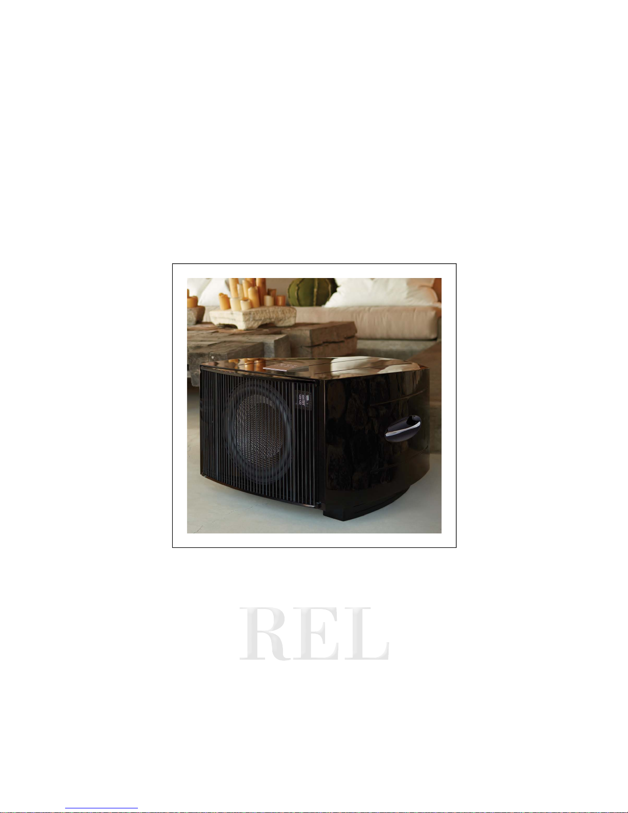
Thank you for purchasing your new REL No.25, this unit is produced with great pride and operates as the
standard bearer summarizing a journey that has taken REL 25 years to achieve. As the commemorave
unit marking 25 successful years, the No.25 takes all the best technologies developed over the past quarter
century and adds a few important design improvements to create a new standard to carry us on to the
next 25 years.
Scale and Power: There is, as the saying goes, no replacement for displacement. Our development of a
super, light, fast 15 inch driver was no easy task and it took quite some me to nd a manufacturer capable
of building to our standard. Anyone can build a big, loud 15 inch driver; the hard part lies in keeping it
lightweight and yet s enough to hold up to the rigors our customers regularly put their units through.
160 square inches, capable of moving 2” fore and a (total stroke of 100mm or approx. 4”) of specially
prepared, woven carbon bre allows for massive wave-fronts to be developed. And yet, what will surprise
serious students of the infra bass art is the speed, texture and liquidity this driver expresses. But for the
eortless extension and power it produces in spades, it sounds even faster than a great 10” driver.
Un-corrupble Power: REL required serious power to unlock the performance potenal of the No.25 driver
and so we turned to our newest amplier design, a specially developed Class D amplier that produces a
connuous 1,000 was and can deliver yet higher output on peaks. Naturally, this amplier has already
proven itself to be rugged and reliable in the eld so feel comfortable trusng our commemorave design
to this beast of an amp.
It All Begins Up Front: To this bulletproof amplier and driver combinaon, we applied the legendary lter
set we developed for the No.25; these are the fastest lters we have ever measured at just 4 ms and a
crossover that begins as low as 20Hz. Beyond simply technical bragging rights, they are the most natural
sounding lters we have ever experienced.
Taming the Room: We don’t believe in room correcon, too oen this is the bason of those who would
rather not get it right in room design nor set-up, but believe they can “correct” it all with an enormously
complicated lter called room correcon. There is no free lunch in high end audio and the price that must
be paid is loss of impulse response (speed and dynamics)—not to menon highly variable results using
these computerized aempts to x all.
We have chosen to include not 1 but 2 parametric equalizers using specially developed REL-fast lters. Each
lter permits boost or cut of 6 dB, a perceived doubling or halving of output in a narrow frequency range.
REL Parity™ allows the advanced set-up arst the ability to idenfy room modes, both peaks and dips, and
Dear No.25 Owner

9
smooth out the overall in-room response. While it takes a lile pracce (and generally a gentle hand on the
controls is highly recommended) the results are highly grafying. Use it to gently ll in an area that requires
more output and then gently cut bass in the upper range that is too exuberant.
A Beauful Body: The curvaceous cabinet is designed to push further the experience of minimizing internal
cabinet resonances by creang a curvilinear cabinet that does not permit any single frequency from building
up a dominant mode. It is this s, fully-braced like a ne musical instrument design that allows the full
palee of tonal colors to emerge from No.25 along with the prodigious dynamics for which it is quickly
becoming known. Even the Bass String™ grille has been designed with an eye to beauty and airow, allowing
enormous displacement of air to pass through without restricon, where a convenonal grille would muddy
the sound.
In sum, the No.25 puts into pracce all the many lessons – and more – learnt by REL along its 25 year
journey-to-date. We look forward to enjoying the next 25 with you, many thanks for allowing us to serve you.
Sincerely,
John Hunter

Remote Control
1 Crossover: Used to adjust crossover frequency. Variable between 20-90Hz.
2 .1/LFE Level: Used to adjust output level when using .1/LFE input from a surround-sound processor.
Also used to adjust Parametric EQ frequency.
3 High/Low Level: Volume control for High/Low Input. Use to adjust output when using either High Level
or Low Level input. Also used to a adjust Parametric EQ level.
4 Filter: Used to select lter operaon.
5 Phase: Used to set phase 0-180 degrees.
6 Security: Used to lock remote sengs. To extend baery life of the remote, always leave the toggle
switch in the locked posion when not in use.
10
REL No.25 Remote Control and Rear Panel Legends
1
23
4
5
6

11
REL No.25 Rear Panel Connecon Legend
1 .1/LFE RCA Input: Used to connect to the .1/LFE output of a surround-sound processor.
2 .1/LFE RCA Output: Used to connect or “daisy chain” another REL No.25 in tandem.
3 Le & Right Channel Low-Level RCA Input: Used to connect low-level signals to the sub-bass system from
the output of a preamplier, integrated amplier or receiver. (For home cinema use, use .1/LFE input).
4 High Level Input (Neutrik Speakon): Used to connect to the main front amplier speaker terminals.
5 High Level Output (Neutrik Speakon): Used to connect or “daisy chain” another REL No.25 in tandem.
6 .1/LFE Balanced Input: Balanced (XLR connector) version of .1/LFE Input. For use only with fully
balanced cables.
7 .1/LFE Balanced Output: Balanced (XLR connector) version of .1/LFE Output. For use only with fully
balanced cables.
8 Ambient Trig: Used to turn ambient light on the underside of the sub on and o by a 12VDC trigger
9 Ambient Control: Used to pre-set the amount of ambient light from the underside of the sub.
10 Parametric Filter: Used to engage parametric lter into the signal path.
11 Antenna Connector: Used with REL Longbow™ transmier.
12 Pair Pilot Light: Indicates if unit has been paired with REL Longbow™ transmier.
13 Pair Switch: Used to iniate pair sequence with REL Longbow™ transmier.
14 Wireless enable switch:Used to turn on wireless receiver when connected to REL Longbow(TM)
wireless transmier.
15 Standby/Always On Switch: Used to enable standby mode.
16 Power Pilot Light: Power On/O indicator.
17 Power On/O Switch: Use to turn unit on or o.
18 IEC Mains Socket: Fused mains (AC) input socket that accepts detachable power cord.

12
8 9
10
11
12
13
1 2 3
4 5 6 7
14
15 16
17
18

13
High-Level Input
Connecons should be made to the same binding post on main amplier as the main speakers. Red to amplier main
right speaker red terminal, yellow to amplier main le speaker red terminal and black to amplier main speaker
black terminal, right or le but not both. Plug the Neutrik® Speakon® plug into the HI LEVEL Speakon® socket.
.1 Input
This requires a RCA to RCA or XLR to XLR cable and is a dedicated true .1 channel. This circuit therefore
eliminates the normal Natural RollO™ Crossover and passes the .1 low-level signal through with only the
required 120Hz fourth-order lter.
Low-Level Input
The RCA inputs allow for convenonal connecon from a preamplier and should be used in the rare event
that a high-level connecon proves incompable. Plug one end of the RCA to RCA cables into the LOW
LEVEL INPUT jacks of the REL and the other end into the le and right channel output of your preamplier.
Phase Switch
Used to set phase. Phase Switch on remote control is momentary. Refer to display for 0 or 180 degree status.
Phase selecon aects High Level, Low Level and .1/LFE inputs.
PHASE SELECTION AFFECTS BOTH HIGH AND LOW LEVEL INPUTS
Crossover is always engaged for high and low level inputs. The .1/LFE signal does not pass through the
crossover circuit.
Filter
The No.25 can employ a two band parametric EQ lter. With the top Filter switch in the center locaon the
remote acts in normal operaon. With the switch in the far le posion, the .1/Level control on the remote
changes the frequency of EQ lter 1, and the Hi/Lo Level control on the remote changes the level of EQ lter 1.
With the switch in the far right posion, the .1/Level control on the remote changes the frequency of EQ
Connecvity and Funconality

14
lter 2, and the Hi/Lo Level control on the remote changes the level of EQ lter 2. Each lter has a frequency
range from 20Hz to 90Hz. The level set of each lter is +/- 6 dB in 1/3 dB increments.
LED Display
An LED display is located on the upper right front of No.25. All funcons that are user adjustable via the
remote control can be seen here. The display reverts to o a few seconds aer adjustment. The top three
characters indicate the parameter being controlled by the remote and the boom two numbers indicate
the value of the parameter controlled.
Parameter Display
High/Low Level HL
.1 Level .1
Crossover Frequency CO
Phase PH
Parametric EQ1 E1
Parametric EQ2 E2
Ambient Control
No.25 has an array of ambient lights on each side, outboard of the feet. The intensity of these lights can
be controlled with the 4 posion AMBITET CONTROL switch. Starng with the switch in the far counter
clockwise posion, the lights are o, as the switch in moved to the next three posions, the intensity will
increase. The ambient lights can be triggered o for theater viewing with a common 12VDC trigger. 0V at
AMBIENT TRIG keeps the lights ON, +12V at this trigger input turns them OFF.
Remote Control Baery Installaon
No.25’s Remote Control Unit requires two AAA baeries. These are not installed but are supplied. To install
or replace baeries in the Remote Control Unit, rst remove the boom aluminum cover by using the
supplied 2.5mm Hex key to loosen the two visible screws. With the boom cover removed, you will see a
baery holder, which will accept two AAA baeries. Follow the images on the holder for proper orientaon
of the baeries. Aer installing the baeries, test the unit by seng the SECURITY switch to UNLOCK and
turning one of the knobs. If the baeries are installed properly, you will see one of the red LEDs on the
remote control’s front panel illuminate. Replace the boom cover and ghten the two screws using the
supplied Hex key. Baery life can be extended if the SECURITY toggle switch is le in the LOCK posion
when the Remote Control is not in use.

15
Always switch o your system before disconnecng any wires.
To increase the versality of connecng up, the No.25 models have three separate inputs. A high-level input
socket, a .1/LFE input consisng of both RCA and XLR connectors, and a low-level input that includes two
RCA sockets for stereo input. This is to facilitate use with both two-channel stereo systems and AV surround
sound systems.
The high-level, unbalanced, dual-channel (stereo) input is via a Neutrik® Speakon® connector is designed to
accept the stereo (two-channel) signals from the speaker terminals of your receiver, integrated amplier or
basic amplier. This has the advantage of ensuring that your subwoofer receives exactly the same signal as
the main speakers, which means that the character of the bass from the main system is carried forward into
the Sub-Bass System.
This is a very important point and together with REL’s Natural RollO™ circuitry, ensures far superior system
integraon of the Sub-Bass System with the main system.
To engage the Neutrik® Speakon® plug, insert fully into socket and rotate clockwise unl locked.
To remove the Neutrik® Speako n® plug , grip body of plug , place thumb on chro me lever, move lever b ac kward s,
rotate plug anclockwise quarter turn and withdraw.
There are two RCA sockets for low-level connecon to the output of a stereo preamplier or receiver. Another
single RCA socket connects to the .1/LFE output of a home cinema processor.
HIGH LEVEL and .1/LFE inputs can be used simultaneously. The benets are two-fold when used with a
home cinema processor. The low-level input reproduces the .1/LFE channel and the high-level connecon
underpins the main front speakers. The main front speakers should be set to the ‘large’ opon on the
processor. See “theatre Applicaons” for more informaon.
Connecng Up

REL products are not tradional subwoofers, but true Sub-Bass Systems. A REL is designed to augment the
performance of “full range” speaker systems in order to provide, in certain cases, linear response below 15Hz.
Therefore, for the moment, please set aside everything you’ve been taught about subwoofers and how they
are integrated into a stereo or home cinema system. REL Sub-Bass Systems set-up and posioning diers
from convenonal subwoofers. A REL will take advantage of physics and room acouscs to provide deep
pressurizaon as no tradional subwoofer can. It is important that you bring to the set-up process a willingness
to do things a lile dierently in order to obtain these superior results. The end result of your labors will be
an uerly seamless integraon of true deep bass to a sound system, regardless of the main speakers’ low
bass capability.
Basic set-up should take no more than ten to een minutes to accomplish once connected.
Two Things Before You Begin
1 It is helpful to know that you will almost always connect the REL to the input on the rear panel labeled
“HIGH-LEVEL INPUT.” This connecon is made using the supplied 32’ 10” (10 meters) cable, the bare
leads of which connect to the speaker output terminals of the power amplier. The easy and foolproof
connecon at the REL is done with a Neutrik® Speakon® connector. The purpose of connecng to the
speaker output terminals is one of the unique secrets of REL’s success. By connecng to the High Level
input on the REL from the amplier, you build forward the sonic signature of your main system, including
the tonal balance and ming cues of the enre electronics chain. In this way, the REL is fed the exact
signal that is fed to the main speakers.
2 When possible, the REL should be placed in one of the corners behind the speakers. Remember, we are
dealing with true LOW bass pressurizaon with RELs. Low bass pressurizaon below 40Hz is best derived
from corner placement, where the most linear and ecient low bass can be produced because the
subwoofer is able to take advantage of the tangenal (corner-to-corner) axis which is typically the
longest axis in a room.
Connecng and Seng Up
High-level connecon, using the enclosed cable with the Neutrik® Speakon® connector, is always the rst
choice. This connecon can be made without aecng the performance of the amplier because the REL’s
amplier input impedance is 150,000 ohms, in eect producing NO addional load on the rest of your system.
16
REL Set-Up Made Simple

17
• The standard high-level hook up procedure is: aach the red wire to the amplier’s right posive speaker
output terminal; aach the yellow wire to the amplier’s le posive speaker output terminal; aach
the black wire to whichever of the amplier’s ground output terminals is convenient; plug the Speakon®
connector into the Sub-Bass System’s high-level input.
• For dierenal (i.e. fully balanced) ampliers using one REL, simply use the standard connecng scheme
with the excepon of NOT connecng the black wire to a negave speaker terminal. Instead, it should
rst be allowed to “oat” or hang down without connecon to ANY terminal. Should hum occur using
this method, please try connecng to an unused RCA connector on the rear of a preamp or amplier.
Please contact your dealer should there be any quesons concerning this or any other hookup procedure.
NOTE: No.25 models are equipped with internal circuitry to allow connecon to many Class-D (digital)
ampliers. Warning: Do NOT connect the Black wire to the main Class D power amplier’s speaker ground
terminal. Some Class D ampliers produce posive voltage at the amplier’s speaker ground terminal (black)
Standard High-level
Dierenal (i.e. Fully Balanced)

18
and connecng the REL’s ground will produce an undesirable shorng to ground. If connecng to a Class-D
amplier, follow the above connecon procedure for dierenal ampliers.
• When connecng RELs to Mono Bloc ampliers (2) RELs, one for each amplier, must be used. Connect
the black wire of each REL to the negave speaker terminal of the corresponding amplier channel; twist
together the red and yellow wires of each REL separately and connect each pair to the posive speaker
terminal of the corresponding amplier channel. In some instances, this will result in exceponally high
gain (output) from the RELs. If it seems simply too high in gain, please remove either the red or yellow
wire from the twisted pair. This will reduce output by half and restore a natural dynamic.
If the amplier is of balanced dierenal design, please follow the instrucons in the secon above labeled
Dierenal Connecon.
Mono Bloc
Mono Bloc Dierenal

19
• If connecng a single REL as a dedicated centre channel sub, an insider p is to consider connecng to
the rear of the speaker, rather than roung the REL High Level enable all the way back to the amplier.
Connect the black wire of the REL to the negave centre channel speaker terminal; twist together the
red and yellow wires and connect this paired cable (red/yellow paired together) to the posive centre
channel speaker terminal.
• If connecng a REL as a dedicated rear channel sub, connect the black wire of the REL to either the le
rear or right rear negave speaker terminal; connect the yellow wire to the le rear posive speaker
terminal; connect the red wire to the right rear posive speaker terminal. If the amplier is of balanced
dierenal design, please follow the instrucons in the secon above labeled Dierenal Connecon.
Low-level connecon (via RCA connectors) is always an opon if high-level connecon is not possible. When
connecng to the low-level inputs in a system in which high-level connecon is not possible, such as if using
internally-amplied speakers, connect le and right RCA cables between the LOW LEVEL INPUT jacks of the
REL and the le and right channel outputs of your preamplier.
Dedicated Centre Channel
Dedicated Rear Channel
Table of contents
Other REL Acoustics Subwoofer manuals

REL Acoustics
REL Acoustics T1 User manual

REL Acoustics
REL Acoustics Habitat1 User manual

REL Acoustics
REL Acoustics Gibraltar Series User manual

REL Acoustics
REL Acoustics T/i Series User manual

REL Acoustics
REL Acoustics G1 Mk II User manual

REL Acoustics
REL Acoustics R-205 User manual

REL Acoustics
REL Acoustics Q Series User manual

REL Acoustics
REL Acoustics S/2 User manual

REL Acoustics
REL Acoustics Serie R User manual

REL Acoustics
REL Acoustics 212/SE User manual