RelaDyne LUBRIMATE User manual

Rev. 3F Aug 2020
P/N 77740213
INSTALLATION & OPERATION
MANUAL
MODEL NO.
SERIAL NO.
LubriMist
MIST PRESSURE SWITCH RATING
OIL HEATER
VOLTS WATTS
P.O. BOX 19294
HOUSTON,TEXAS 77224-9294
713/464-6266
·
FAX 713/464-9871
·
1-800-800-LUBE
www.lsc.com
THE RIGHT CHOICE
Lubrication
Systems
Company
FULL
ADD
OIL LEVEL
LUBRIMATE®LUBRICATION SYSTEM

Rev. 3F Aug 2020
P/N 77740213
Page 1
LubriMate®Lubrication System
INSTALLATION AND OPERATION MANUAL - P/N 77 740 213
Model Code
WLM -
OPTION DESCRIPTION
X
NO OIL HEATER w/ THERMOSTAT
H
OIL HEATER w/ THERMOSTAT
INCLUDED
X
NO LOW MIST PRSSURE SWITCH
S
LOW MIST PRSSURE SWITCH
INCLUDED
X NO ACCESSORY PACK
A ACCESSORY PACK INCLUDED
.Standard Model is WLM-XXX
Introduction
The LubriMate®Oil Mist Lubrication System provides oil mist lubrication to rotating machinery and equipment. Its design allows
for easy installation and use during equipment operation. The LubriMate®Oil Mist Lubrication System is designed for application
to bearings, gearboxes, chains, and sliding surfaces in various industrial machinery and equipment that will be lubricated with oil
mist. The unit requires a clean and dry compressed air supply to generate the oil mist. Units equipped with oil heaters require a
separate circuit protected electrical power supply. The optional low mist pressure switch has a SPDT contact for wiring to the
users alarm circuit or enunciator. The unique design with coalescing filter eliminates stray mist from venting at the unit thus test
stands remain clean and free of oil mist. This publication provides instruction and information on the set-up and operation of the
unit.
Description
The LubriMate®is a recirculating oil mist system; it produces and delivers the oil mist plus it captures returned liquid oil and
coalesces returned oil mist for continuous reuse and recirculation. The air venting from the unit is essentially hydrocarbon free.
As with other LubriMist®products, the equipment is based upon proven oil mist lubrication technology and utilizes manufacturer’s
proprietary Vortex mist generation technology to deliver superior reliability and performance.
MODEL NO.
SERIAL NO.
LubriMist
MIST PRESSURE SWITCH RATING
OIL HEATER
VOLTS WATTS
P.O.BOX 19294
HOUSTON,TEXAS 77224-9294
713/464-6266
·
FAX713/464-9871
·
1-800-800-LUBE
www.lsc.com
THERIGHT CHO ICE
Lubrication
Systems
Company
FULL
ADD
OIL LEVEL
Return Oil Connections
Supply Air Connection
Air Stripper
Assembly
Supply Mist Connections
Optional Oil Heater
Optional Low Mist
Pressure Switch
Mist Pressure
Gauge
Aluminum Reservoir with Oil Level
Gauge and Oil Temperature
Vortex Mist Generating Head
Fill Port
Return Pressure Gauge
Relief Valve

Rev. 3F Aug 2020
P/N 77740213
Page 2
The unit includes corrosion resistant aluminum reservoir having a 1 1/2-gallon charge capacity. The Vortex oil mist generating
technology and a highly efficient oil stripping system supplies and reapplies a continuous clean lubricant to bearings. Other
standard features include an oil level sight glass, oil temperature gauge, mist pressure gauge, fill and drain ports, relief valve, and
outlet and return connections for bearing hook-ups. Inlet air controls include an integral air filter/pressure regulator.
Optional features include an oil heater and low mist pressure switch. Fittings and hardware sufficient for lubrication of up to 5
lubrication points may also be included when ordering. See the LubriMate model code chart for ordering information.
Lubricant is supplied to the serviced equipment bearing housings from any of five outlet connections located on the top of the
reservoir. The lubricant/air mixture is conveyed through tubing, metered by an application fitting, and then introduced into the
bearing housing. A drain tube connects the bearing housing drain to any of five return ports located on the LubriMate®. The air
stripper separates the remaining oil from the returned oil mist. This coalesced oil is combined with the liquid oil from the bearing
housing and returned to the oil reservoir. The supply and return pressure gauges provide a visual verification that proper system
operation is being maintained.
When included the LubriMate®comes complete with the following installation accessories. Check to insure all items are identified
before beginning installation and operation.
Quantity
Part Number
Description
1
77-700-725
LubriMate®Lubricator Unit
5
77-800-501
Mist Reclassifier, Rated 0.09 SCFM @ 20” H2O
5
77-800-502
Mist Reclassifier, Rated 0.18 SCFM @ 20” H2O
5
77-800-503
Mist Reclassifier, Rated 0.30 SCFM @ 20” H2O
5
77-700-750
Supply Tube Fitting Connector, 1/4”T x1/4”P
5
77-600-992
Supply Tube Fitting Connector, 1/4”T x1/8”P
5
77-600-996
Tube Fitting Plug, 1/4”T
50 Feet
77-600-999
Supply Tubing, 1/4” OD
10
77-700-093
Return Tube Fitting Connector, 3/8”T x1/4”P
5
77-700-768
Tube Fitting Plug, 3/8”T
50 Feet
77-700-752
Return Tubing, 3/8” OD
2 Gallons
LSO681
LubriMistSynthetic Oil ISO 68 (one gallon container)

Rev. 3F Aug 2020
P/N 77740213
Page 3
Mounting and Location
Locate the LubriMate®beside the machine to be serviced. Choose a location that allows enough room for air, oil fill and drain
connections, and electrical service as needed.. Insure easy access to the front of the unit for inspecting and monitoring gauge
settings. The mist supply and return connections on the LubriMate®should be below all bearing drain/oil return connections of the
equipment to be lubricated and low enough to insure that the supply and drain tubing can be installed without sags or traps.
Locate the LubriMate®near the horizontal mid point of all bearings to be serviced. The LubriMate®Lubricating System should be
installed in work areas that are well ventilated. As with any equipment that utilizes compressed air, the area in which it is installed
should evacuate to an exterior open space.
Compressed Air Supply
Connect a clean, dry compressed air supply to the inlet air pressure regulator/filter (1/8” NPT) located at the left side of the unit.
The inlet air supply should be capable of delivering 4 SCFM at 55 PSIG. This is the minimum required air pressure. Installation
of a block valve at the source is advisable. The air supply should be dry and free of water. Instrument quality is recommended.
Application to Equipment
The LubriMate®Lubrication System may include application fittings, tubing and tubing connectors for supplying pure oil mist up to
five bearing housings. If the machinery to be tested or lubricated uses other than anti-friction ball bearings, purge mist application
should be used as described later in this manual.
IMPORTANT
Maximum inlet air supply pressure is 125 PSI. Excess pressure may result in damage
to the inlet air pressure regulator.
Typical LubriMate®Installation
Polyethylene Supply Tubing, ¼” OD
Reclassifier Fitting Installed In
Bearing Housing
Polyethylene
Return Tubing,
3/8” OD
Inlet Air Supply
1/8” NPT
Connection
Bearing
Housing
Bearing
Housing
Bearing
Housing
LubriMate Lubricator
Return Conduit Extension, ½ Pipe (above)
Supply Conduit Extension, ½ Pipe (below)

Rev. 3F Aug 2020
P/N 77740213
Page 4
Pure Mist to Rolling Element Bearings
Lubrication is achieved by insuring that the oil mist flows through the bearing prior to being vented from the drain connection or
through the shaft end seals. The proper path for the mist is from one side of the bearing to the other, flowing parallel to the
spindle shaft. Application fittings should be installed in the upper hemisphere of the bearing housing and not on the LubriMate®.
Flow from the reclassifier should be directed downward from the horizontal. The mist should be required to pass through no more
than two rows of rolling elements (double row ball bearing). To contain the oil mist and avoid venting into the surrounding area,
positive seals around shafts should be provided. Anti-friction bearings supporting either horizontal or vertical shafts may be
lubricated with pure oil mist.
Purge Mist to Gear Boxes and Plain/Sleeve Bearings
The LubriMate®Unit may also be used to purge machinery gearboxes and bearing housings having plain or sleeve type bearings.
Because these type of machinery elements generate a great deal of frictional heat, the pure oil mist with no sump oil as described
above is not suitable unless special designed considerations are provided by the original equipment manufacturer. The design
and application of oil mist to machinery elements, other than anti-friction rolling element type bearings, without the original
recommended oil level is not in the scope of this publication. For gear boxes and sleeve bearings with oil level the purge oil mist
method is to be used.
With purge mist, the air space above the oil level is filled with oil mist. The resulting purge keeps outside contamination from
entering the bearing housing during cool down should the machinery be turned on and off. The LubriMate®also continuously
deposits a thin film of clean lubricant on all equipment internals, giving them additional protection during equipment shutdown,
start-up, and operation. Purge application requires the use of LubriMist®purge mist application. LubriMist®purge mist
accessories are available for purchase from manufacturer.
The LubriMist®Purge Mist Vent/Fill Assembly should be installed directly in the upper hemisphere of the bearing housing above
the oil level. When the LubriMist®Purge Mist Vent/Fill Assemblies is used, install a size 501 reclassifier directly into the mist inlet
of the assembly. Flow should move downward from horizontal.
The LubriMist®oil level site assembly is designed to maintain proper oil level in the bearing housing. Also, with the installation of
the pressure balance line, the internal housing pressure is maintained at atmospheric pressure so that oil level in the housing is
not affected.
IMPORTANT
When connecting a bearing
housing where an operating
oil level is to be maintained,
insure that the internal
housing pressure does not
adversely affect the oil level.
Purge mist, vent/fill
assembly
77-800-501
Reclassifier
Supply tubing;
¼” OD
Drain tubing;
3/8“ OD
Oil level site
assembly with
pressure balance
line
Provide positive shaft seals
Drain tubing, 3/8“ OD
Mist reclassifiers
Supply tubing; ¼” OD
Lubricating Anti-Friction Ball Bearings

Rev. 3F Aug 2020
P/N 77740213
Page 5
Selection of Application Fittings (Mist Reclassifiers)
Included with the LubriMate®Unit are three sizes of application fittings (mist reclassifiers). A quantity of five for each type of
application fittings is provided to suit a range of oil mist flow requirements:
•77-800-501; Mist Reclassifer, Rated 0.09 SCFM @ 20 In H2O
•77-800-502; Mist Reclassifer, Rated 0.18 SCFM @ 20 In H2O
•77-800-503; Mist Reclassifer, Rated 0.30 SCFM @ 20 In H2O
Pure Mist
For oil mist lubrication of anti-friction/rolling element bearings under normal operating conditions, two factors are to be considered:
the shaft diameter at the bearing and the number of rows of bearings. The table below should be followed to select the correct
size reclassifier.
Pure Mist: Anti-Friction/Rolling Element Bearings
Shaft Diameter @ Bearing Single Row Bearing Double Row or Duplex Bearing
< 1.77 in. (45 mm) 77-800-501 77-800-502
1.77 in. (45 mm)
to
2.95 in. (75 mm) 77-800-502 77-800-503
>2.95 in. (75 mm)
to
5.51 in. (140 mm) 77-800-503 Use Purge Application or Consult
Your manufacturer Representative
Purge Mist
With purge mist, the lubrication of the machine elements is maintained by the splash or recirculation of the oil from the oil
reservoir. The purge mist itself does not provide the lubrication rather it fills and flows through the volume space above the oil
level. Therefore, achieving adequate flow through that volume is important and should be considered when selecting reclassifiers
for purge mist applications. The sizing requirement is established by knowing the approximate volume space above the oil level.
The following table provides guidelines for selecting the correct reclassifier for purge mist applications.
Purge Mist: Sleeve Bearings and Gear Boxes
Internal Volume
(Volume Space
Above The Oil Level)
Less Than 2 Cubic Feet
(56 Liters) 2 Cubic Feet
(56 Liters) or More
Mist Reclassifier 77-800-501 77-800-502
IMPORTANT
The last three digits of the part number are stamped on the mist reclassifier. Inspect the mist
reclassifier to insure that the correct part is being installed.
IMPORTANT
1. Mist reclassifiers are to be mounted on the equipment receiving the oil mist and not
on the LubriMate®except when additional flow is required as described below.
2. If the equipment to be operated or tested will rotate at speed greater than 3600
RPM or will be tested or operated under conditions that place extreme thrust
loading on the bearings, consult your manufacturer representative.

Rev. 3F Aug 2020
P/N 77740213
Page 6
Supply And Return Tubing Installation
The installed 1/4” supply tubing and 3/8” vent and drain tubing should be sufficiently long so that there are no kinks or twists.
These obstructions can restrict flow to the bearing or hamper drainage from the bearing housing. Additionally sags and traps are
to be avoided by making the lengths too long. Sags or traps will collect oil and affect the flow of oil mist to the bearing or the mist
return to the LubriMate®. Tubing should bend smoothly as changes in direction are made. The maximum length of supply tubing
to an application point should be less than three (3) meters. A similar length restriction applies to drain tubing.
Ambient Operating Temperature
The LubriMate®uses the power of compressed air to generate the oil mist for bearing lubrication. The ability to create the oil mist
is directly influenced by the viscosity of the lubricant. As ambient temperatures fall and oil viscosity increases, oil mist generation
decreases. Below certain temperatures, the LubriMate®will not produce oil mist.
Where the LubriMate without the optional oil heater it is recommended that the LubriMate®be operated at ambient conditions
above 50 degrees F. The LubriMate®Lubrication System is shipped with a supply of ISO 68 grade, diester type lubricant. Use the
following chart as a guide for selection and use of other viscosity grades. For units equipped with an oil heater, the it is
recommended that the oil temperature be set at 110 F. This helps to maintain a consistent
Viscosity Grade
Minimum Operating Temperature
ISO 32
32 F ( 0 C)
ISO 46
40 F ( 4.4 C)
ISO 68
50 F ( 9.9 C)
ISO 100
60 F (15.6 C)
ISO 150
70 F (21.0 C)
>ISO 150
Not Recommended
Maintaining Minimum Air Flow to the LubriMate®
To insure proper generation of oil mist a minimum airflow must be provided to the internal mist head in the LubriMate®. If the
application requires only one lubrication point or a combination of mist reclassifiers that have a combined flow of less
than 0.40 SCFM, additional airflow is needed for proper operation. The LubriMate®is equipped with an internal mist flow
bypass valve, which can be used to increase or decrease the mist output volume. The mist bypass valve is located on the right
side of the mist generator head. Opening the mist flow bypass valve directs mist flow directly into the mist recovery system, thus
increasing output mist flow volume.
LubriMate®Lubrication System oil mist generators are shipped with the mist flow bypass valve in the OPEN position. If your total
mist out put is 0.40 SCFM, close the mist flow by pass to the full closed position. The valve is in the full closed position when
the adjust valve is fully turned in and seated. It is in the full open position when the face of the valve is flush with the edge of the
mist generator head. See the section of this manual titled Selection of Application Fittings (Mist Reclassifiers) to determine the
mist output of your system.
IMPORTANT
1. Do not use oil that
contains paraffin or
viscosity modifiers.
2. Do not use motor oil in
the LubriMate®.
Mist Flow Bypass Valve
Adjust CW to the full
CLOSED position if the total oil
mist output is 0.40 SCFM
Adjust CCW to full OPEN
position if the total oil mist
output is < 0.40 SCFM (factory
setting)

Rev. 3F Aug 2020
P/N 77740213
Page 7
Start-Up Procedures
Once the mist reclassifiers, mist supply and drain tubing, and the air supply line have been installed and connected, system can
be started by following these steps:
1. Fill the reservoir to the fill mark. DO NOT OVERFILL! The oil fill port is located on the left side of the reservoir. A supply of
ISO 68 grade lubricant is included with the LubriMate®. Although this grade of oil will suit the lubrication requirements for the
majority of all applications, a check should be made to insure suitability for the equipment being serviced. If your model is
equipped with an oil heater, energize the heater. Check thermostat so that the oil temperature operates at approximately
110F.
2. Make sure the air stripper valve is closed by turning clockwise.
3. Turn on the air supply connected to the inlet air pressure regulator and adjust the air pressure regulator knob clockwise until
the mist pressure gauge reads 20 inches (500mm) of H2O. At this point oil mist is being produced and flowing to the
bearings. THE SUPPLY AIR FLOW SHOULD NOT BE CHANGED FOR THIS PARTICULAR SET-UP FROM THIS POINT
FORWARD! The oil mist output is now established by the airflow through the Vortex Mist Generator.
4. Open the air stripper control valve by turning counter-clockwise until the return mist gauge reads -0.10 to -0.15 inches of H2O
(vacuum) and the oil mist venting from under the return filter cap is no longer visible. The mist supply pressure will increase
to approximately 30 to 50 inches of H2O. This increase in mist supply pressure is derived from the coalesced oil being
injected back into the oil reservoir. DO NOT ATTEMPT TO RE-ADJUST THE MIST PRESSURE BACK TO 20” H2O.
I
System Operation and Adjustment
As the system operates over time, the stripping filter element becomes saturated with oil. This is normal and expected. However
the resulting increased pressure drop across the filter may cause a portion of the returning mist to bypass the filter and be vented
from under the stripper filter cap. This occurs when the return pressure starts to increase to a slight positive pressure. To
remedy this situation, open the air stripper control valve slightly by turning counter-clockwise until only clean air is vented and the
filter element return pressure again reads -0.10 to -0.15 inches of H2O (vacuum). Several adjustments may be necessary as the
filter element becomes saturated but a steady state condition will be reached and further adjustment will not be necessary.
As adjustments to the air stripper control valve are made, the mist supply pressure will increase. Do not adjust the air pressure
regulator in an effort to return the supply mist pressure to 20 inches of H2O. THE PROPER MIST SUPPLY VOLUME IS
ESTABLISHED WHEN THE AIR STRIPPER CONTROL VALVE IS IN THE CLOSED POSITION DURING STEP 4 OF THE
START-UP PROCEDURE. Once the filter element is saturated and final adjustment to the air stripper control valve is made, the
LubriMate Start-Up Sequence
NOTE:
At start-
up and once oil mist is generated, delivered to the bearings, flows through the housing and returns to the
LubriMate®, excess returned oil mist will vent from under the filter cover a
nd be visible. This is normal and to strip this
oil mist from the venting air, follow the procedures in Step 4. Although oil mist is non-
hazardous, one should avoid
breathing the mist during start-up.
Step 2:
Close air stripper valve
Step 4C:
Mist supply pressure gauge
reads 30 to 55 inches of H2O
Step 1:
Fill reservoir
Step 3A:
Turn on air supply
Step 4A:
Open air stripper valve
Step 4B:
Adjust air stripper valve until return mist pressure
gauge reads -0.10 to -0.15 inches of H2O (vacuum)
Step 3B:
Set mist supply pressure to
20 inches of H2O

Rev. 3F Aug 2020
P/N 77740213
Page 8
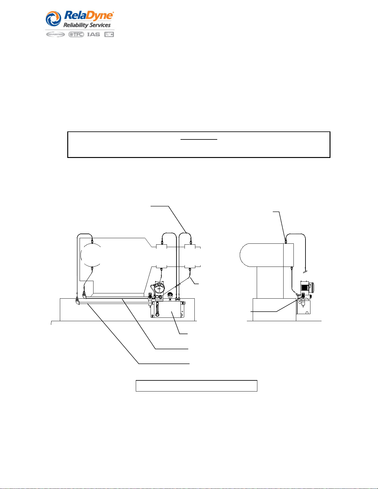
resulting supply mist pressure should be approximately 30 - 55 inches of H2O. Most typical mist supply pressures will be 35 - 45
inches of H2O.
During the first 24 hours of operation, the oil level in the reservoir will drop. This is a result of the internals of the supply tubing
and bearing housing and the stripping filter becoming “wet” with oil. Add lubricant as necessary to bring the oil level to the normal
operating level. When adding lubricant, the air supply to the unit should be closed, preferably using the user installed valve so
that there is no need to readjust the air supply with the pressure regulator.
Trouble Shooting
The operation of the LubriMate®has been reduced to checks of the generator and the lubricated equipment. Except for
emergencies, routine adjustment of the generator is not required. The LubriMate®, once installed and balanced, supplies a
constant amount of oil mist to all lubrication points.
Any change in the supply mist pressure, return pressure, or regulated air pressure (inlet air supply pressure) from initial set points
is an indication that some mist system component or compressed air supply system may have malfunctioned. Adjustments of the
controls to offset the failure symptom may lead to more serious problems before correction of the root cause can be made. If mist
generation is sporadic, seems to fluctuate or is non-existent, check the following:
1. Check reservoir oil level and add if necessary. The operating oil level should be between the “full” and “add oil” marks on
the oil level sight glass.
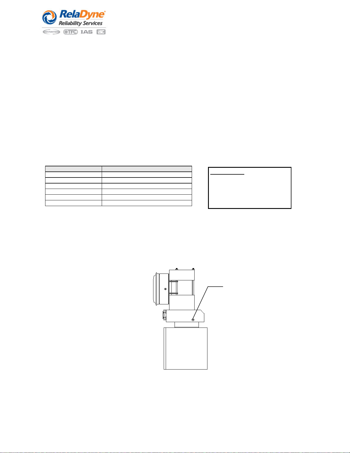
2. Remove and check the oil suction screen for plugging or restrictions. Clean and replace as needed.
NOTE:In order to check the oil suction screen, it is necessary to shut down and restart the LubriMate®.
3. Verify that the LubriMate®is operating within the recommended minimum operating temperature (see page. 6). Variations
in output are directly affected by changes in oil viscosity due to temperature changes.
4. Verify that minimum airflow requirements through the mist generator have been established. See Section “Maintaining
Minimum Air Flow to the LubriMate®” for instruction.
5. Check the mist supply pressure by making a visual check of the mist pressure gauge. Normal operating pressure is 20-35
inches of H2O. Change in the mist supply pressure should not be corrected by adjusting the regulated air supply. Changes
in mist pressure are most likely caused by situations external to the oil mist generator. The following should be
investigated:
5.1. Low mist pressure may indicate a leak or loose connection in the supply tubing, a missing application fitting or a
broken line.
5.2. High mist pressure may indicate plugged application fitting, or a restricted bearing housing vent or drain line.
5.3. No mist pressure could indicate loss of air supply to the mist generator. Check the inlet air supply.
5.4. Surging mist pressure usually is caused by an oil pocket or trap in the distribution header or fluctuating air supply.
6. Check the return mist pressure gauge.
6.1. If the return mist pressure is set too low (due to insufficient vacuum or when a positive pressure exists), inefficient or
ineffective air stripping will result. Adjust if necessary, and recheck mist supply pressure. See start-up procedures for
system adjustments.
6.2. Low return mist pressure (vacuum) may be caused by plugged or restricted return lines. Check all return tubing lines
for low pockets that might trap oil or kinks that can restrict flow. Repair or correct as necessary.
Re-Start Procedure:
A gurgling noise or puffs of visible mist being heard or observed from underneath the
demisting filter is caused by inadequate pressure to the demisting filter assembly.
This may be accompanied by a noted positive pressure on the return mist pressure
gauge. To correct, increase the air supply pressure by adjusting the air pressure
regulator. Turn the adjusting knob clockwise to increase the air pressure until the
return mist pressure gauge reads +0.5 inches of H2O. Allow the LubriMate®to operate
until the mist supply pressure returns to a constant vacuum of +0.4 to +0.5 inches of
H2O. Readjust the air pressure regulator by turning the knob counter-clockwise until
the normal return mist pressure of -0.10 to -0.15 inches of H2O is reestablished.
6.3. Insure that minimum airflow requirements are being maintained. See the section titled Maintaining Minimum Air Flow
to the LubriMate®. Adjust if necessary, and recheck mist supply pressure. See start-up procedures for system
adjustments.
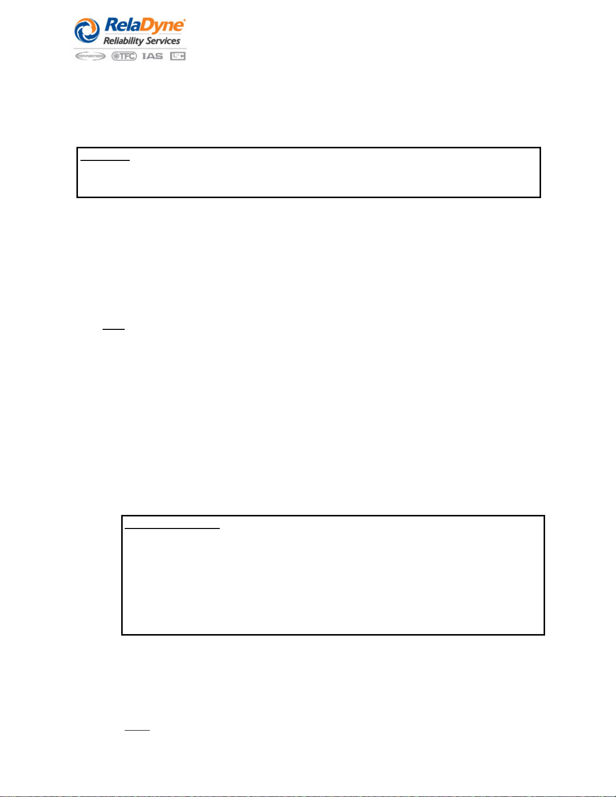
7. Insure that the bulls eye sight glass on the front of the LubriMate®is clear and that oil is not accumulating in the chamber
behind the glass.
7.1. Check the return mist pressure adjustment. Insufficient airflow through the air stripper may be inadequate to purge
the returning liquid oil into the oil reservoir. Adjust if necessary.
7.2. Check the return orifice located behind the bulls eye for plugging or restriction.
NOTE: In order to check the orifice, it is necessary to shut down and restart the LubriMate®.
CAUTION:
Do not adjust the air stripper control valve so as to achieve return mist pressure that is in
excess of -0.15 inches of H2O (vacuum). Improper adjustments may draw outside air and
contamination into the machinery bearing housings and the LubriMate®Lubrication System.

Rev. 3F Aug 2020
P/N 77740213
Page 9
Dimensions
MODEL NO.
SERIAL NO.
LubriMist
MIST PRESSURE SWITCH RATING
OIL HEATER
VOLTS WATTS
P.O. BOX 19294
HOUSTON,TEXAS 77224-9294
713/464-6266
·
FAX713/464-9871
·
1-800-800-LUBE
www.lsc.com
THE RIGHT CHOICE
Lubrication
Systems
Company
FULL
ADD
OIL LEVEL
131
2"
161
2"
223
4"
75
8"
AIR SUPPLY 1/8 NPT
MIST SUPPLY
CONN 1/4 NPT (4)
MIST SUPPLY
CONN 1/4 NPT (5)
7
16"

Rev. 3F Aug 2020
P/N 77740213
Page 10
Parts and Accessories for the LubriMate® Lubrication System
MODEL NO.
SERIAL NO.
LubriMist
MIST PRESSURE SWITCH RATING
OIL HEATER
VOLTS WATTS
P.O. BOX 19294
HOUSTON,TEXAS77224-9294
713/464-6266
·
FAX713/464-9871
·
1-800-800-LUBE
www.lsc.com
THERIGHT CHOICE
Lubrication
Systems
Company
FULL
ADD
OIL LEVEL
ITEM
PART NO.
DESCRIPTION
1
U-902-S
Mist Pressure Gauge, 0-100 inches of H2O
2
77-700-744
Return Pressure Gauge
3
77-700-743
Air Stripping Coalescing Filter Element
4
77-700-742
Bulls Eye Sight Glass
5
LS-02-05-120
Oil Suction Screen
6
77-600-807
Air Filter/Pressure Regulator
7
77-600-089
Oil Fill Cap
8
77-700-741
Pyrex Oil Cup Glass
9
77781017
Oil Level Gauge w/ Thermometer
10
77781018
Relief Valve , 3 PSI, Alum Body
11
LSO681
LubriMist® Synthetic Oil ISO 68, One Gallon Container (not shown)
12
77781016
Low Mist Pressure Switch – Adjustable 7-100 In H2O - (optional feature)
13
77781015
Oil Heater w/ Thermostat – 120 VAC / 250 Watt (optional feature)
((1)
((2)
((4)
(6)
(5)
((8)
((3)
(9)
(10)
(7)
((13)
((12)

Rev. 3F Aug 2020
P/N 77740213
Page 11
Items shown below are available from manufacturer for purge mist application. Items must be purchased seperately
77-600-822 - Purge Mist Vent/Fill Assembly 77-700-217 - Purge Mist Vent/Fill Assembly
Wiring Diagrams for the LubriMate® Lubrication System
LOW MIST PRESURE SWITCH
Oil HEATER
120 VAC - 250 Watt
ALUMINUM PORT
TEFLON COATED POLYIMIDE DIAPHRAGM
ADJ RANGE - 7" H20 (DECR) TO 100" H20 (INCR)
SPST CONTACT RATING;
11 AMP, 1
2HP AT 125 OR 250 VAC
5 AMP RESISTIVE
3 AMP INDUCTIVE AT 28 VDC
5 AMP RESISTIVE AT 125 VAC
EXPLOSION PROFF, HERMETICALLY SEALED
ELECTRICAL ASSEMBLY FOR CL1 DIVISION 2
HAZARDOUS AREAS
120 VAC / 1 PH / 250 WATT
WATT DENSITY 10.6
PLUG - 1” NPT / C.S.
B DIM = 9.375
NEMA 4 / 7 ELECTRICAL ENCLOSURE
CONDUIT CONNECTION AT 12 O-CLOCK POSITION
TYPE 2 THERMOSTAT

Rev. 3F Aug 2020
P/N 77740213
Page 12
Notes and Records
Table of contents
Other RelaDyne Lubrication System manuals