RelaDyne THERMOJET H-2500E Series User manual

THERMOJET®H-2500E SERIES
OIL PURIFIER SYSTEM
INSTALLATION AND OPERATING MANUAL
Doc # 77740119
Rev 15
Date June 2020
Page
1
of
100
ThermoJetH2500E Series
Oil Purifier System
Installation and Operating Manual
______________________
5615 W Fuqua St B-201 •Houston, Texas 77085
1-713.464.6266 •Fax: 713.464.9871
Doc 77740119 Rev 15
READ AND UNDERSTAND THIS OPERATING
MANUAL BEFORE ATTEMPTING TO INSTALL,
COMMISSION, OR USE THIS EQUIPMENT.
FAILURE TO UNDERSTAND THESE
INSTRUCTIONS COULD RESULT IN SERIOUS
PERSONAL INJURY AND OR LOSS OF
PROPERTY.
WARNING

THERMOJET®H-2500E SERIES
OIL PURIFIER SYSTEM
INSTALLATION AND OPERATING MANUAL
Doc # 77740119
Rev 15
Date June 2020
Page
2
of
100
NOTES:
______________________________________________________________________
______________________________________________________________________
______________________________________________________________________
______________________________________________________________________
______________________________________________________________________
______________________________________________________________________
______________________________________________________________________
______________________________________________________________________
______________________________________________________________________
______________________________________________________________________
______________________________________________________________________
______________________________________________________________________
______________________________________________________________________
______________________________________________________________________
______________________________________________________________________
______________________________________________________________________
______________________________________________________________________
______________________________________________________________________
______________________________________________________________________
______________________________________________________________________
______________________________________________________________________
______________________________________________________________________
______________________________________________________________________
______________________________________________________________________
______________________________________________________________________
______________________________________________________________________
______________________________________________________________________
______________________________________________________________________
______________________________________________________________________
______________________________________________________________________
______________________________________________________________________
______________________________________________________________________
______________________________________________________________________
______________________________________________________________________
______________________________________________________________________
______________________________________________________________________
______________________________________________________________________
______________________________________________________________________
______________________________________________________________________
______________________________________________________________________
______________________________________________________________________

THERMOJET®H-2500E SERIES
OIL PURIFIER SYSTEM
INSTALLATION AND OPERATING MANUAL
Doc # 77740119
Rev 15
Date June 2020
Page
3
of
100
Table of Contents
I GENERAL INFORMATION.........................................................................................................................5
Manufacturer Contact Information ..............................................................................................................6
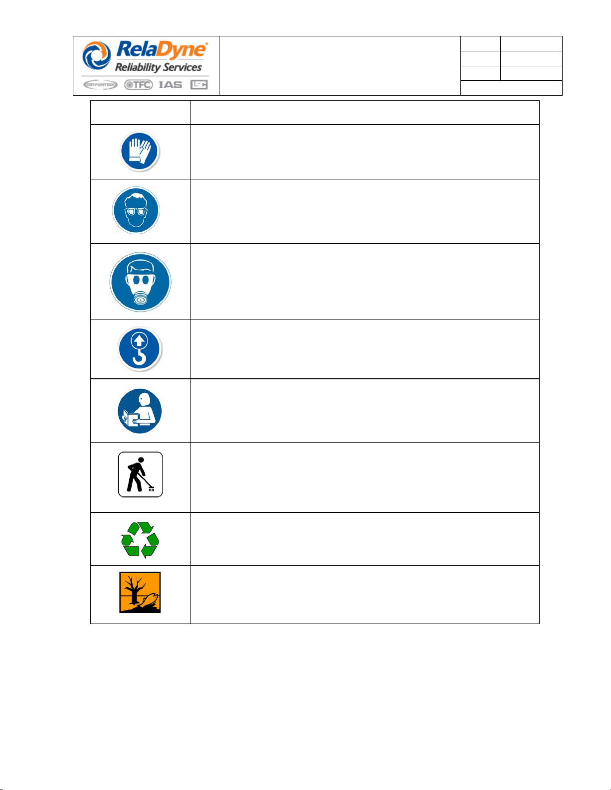
Explanation Of Graphic Symbols In The Documentation ...........................................................................7
II UNIT IDENTIFICATION AND LABELING .................................................................................................10
ThermoJet ® Model H2500- Model Code Designations...........................................................................11
Model Code Designation Key ...................................................................................................................12
Tag Detail for H2500E Model Oil Purifiers................................................................................................13
III DESCRIPTION OF THE PRODUCT........................................................................................................14
Principal of Operation................................................................................................................................15
Dewatering................................................................................................................................................15
Flow through the Unit................................................................................................................................15
The Jet Mixer............................................................................................................................................15
Return of Clean Oil....................................................................................................................................15
MountingOptions ......................................................................................................................................15
IV INSTALLATION........................................................................................................................................16
Receipt Inspection ....................................................................................................................................17
Placement of Equipment...........................................................................................................................17
Inlet and Return Oil Piping Connections...................................................................................................18
Condensate Purifier Connection...............................................................................................................20
System Exhaust Connections...................................................................................................................21
Electrical Power Connection.....................................................................................................................22
Grounding .................................................................................................................................................25
V SYSTEM START-UP AND OPERATION .................................................................................................26
Start-Up Procedures .................................................................................................................................27
Heater Operation:......................................................................................................................................32
Adjusting System Pressure.......................................................................................................................35
System Discharge Pressure .....................................................................................................................36
System Vent Operation.............................................................................................................................37
Monitoring Normal Operation....................................................................................................................39
Dailey ThermoJet Oil Purifier System Operational Checks......................................................................41
System Shutdown.....................................................................................................................................42
VI ROUTINE MAINTENANCE......................................................................................................................43
Maintenance Checks ................................................................................................................................44
General Inspection....................................................................................................................................46
Oil Filter Maintenance...............................................................................................................................47
Y-Strainer Maintenance ............................................................................................................................48
Condensate Purifier Assembly Maintenance............................................................................................49
Oil Mist Eliminator Maintenance ...............................................................................................................50
Air Breather Maintenance.........................................................................................................................51
Separation Vessel Maintenance...............................................................................................................52
Oil Heater Maintenance............................................................................................................................55
Auto Tune Oil Heater Controller................................................................................................................60
Check and Adjust Operating Pressures....................................................................................................62
Verify Low Oil Pressure Switch Operation................................................................................................63
Verify Oil Heater High Temperature Cutout Operation.............................................................................65

THERMOJET®H-2500E SERIES
OIL PURIFIER SYSTEM
INSTALLATION AND OPERATING MANUAL
Doc # 77740119
Rev 15
Date June 2020
Page
4
of
100
VII CLEANING AND DECONTAMINATION.................................................................................................69
Cleaning and Decontamination.................................................................................................................70
Removal From Use, Disposal And Transport ...........................................................................................72
Draining and Cleaning Procedures...........................................................................................................74
VIII TROUBLE SHOOTING..........................................................................................................................75
Trouble Shooting Guide............................................................................................................................76
Quick Reference Troubleshooting Guide..................................................................................................79
Types of Product Misapplication and Misuse Not Covered By Warranty or Guarantees.........................80
IX PARTS LIST / DRAWINGS / SCHEMATICS...........................................................................................81
Maintenance Spare Parts List...................................................................................................................82
Process and Instrument Diagram .............................................................................................................83
PID Symbol Legend and Customer Connection Chart.............................................................................84
Electrical Wiring Diagram..........................................................................................................................85
Transformer Wiring ...................................................................................................................................86
Fuse Ratings and Characteristics.............................................................................................................87
Bill Of Materials.........................................................................................................................................88
General Arrangement Drawings ...............................................................................................................90
Dimensional Outline Drawings..................................................................................................................94

THERMOJET®H-2500E SERIES
OIL PURIFIER SYSTEM
INSTALLATION AND OPERATING MANUAL
Doc # 77740119
Rev 15
Date June 2020
Page
5
of
100
I GENERAL INFORMATION

THERMOJET®H-2500E SERIES
OIL PURIFIER SYSTEM
INSTALLATION AND OPERATING MANUAL
Doc # 77740119
Rev 15
Date June 2020
Page
6
of
100
Manufacturer Contact Information
For additional information contact the manufacturing office nearest you or check our
website.
For questions regarding this publication or if you have specific questions regarding the
installation and operation of ThermoJet®Oil Purifier System, please contact
Manufacturer
5615 W Fuqua St B-201
Houston, Texas 77085
USA
Ph 1.713.464.6266
Fx 1.713.464.7375

THERMOJET®H-2500E SERIES
OIL PURIFIER SYSTEM
INSTALLATION AND OPERATING MANUAL
Doc # 77740119
Rev 15
Date June 2020
Page
7
of
100
Explanation Of Graphic Symbols In The Documentation
The following graphic symbols are used in this publication to communicate specific detailed information
necessary for the safe operation of this product. These graphic symbols are used to create “Safety Alerts”
within the documentation to alert the users of potential hazards, instruction on how to avoid injury and
instruction notices for safe operation. When interfacing with this product it is important these safeguards
are observed.
It is important for safety alerts to have the appropriate choice of signal word because this word and its
colored background communicate the severity of the hazard. The signal word calls attention to the warning
and designates a degree or level of hazard seriousness. The signal words for product safety alerts as used
in this manual are “DANGER”, "WARNING", "CAUTION", and "NOTICE".
SYMBOL SYMBOL DESCRIPTION AND USE
This symbol is used to identify a “DANGER” level of hazard seriousness.
“DANGER” indicates a hazardous situation which, if not avoided, will result
in death or serious injury
WARNING
This symbol is used to identify a “WARNING” level of hazard seriousness.
“WARNING” indicates a hazardous situation which, if not avoided, could
result in death or serious injury
This symbol is used to identify a “CAUTION” level of hazard seriousness.
“CAUTION” indicates a hazardous situation which, if not avoided, could
result in minor or moderate injury
This symbol is used to identify a “SAFETY ALERT” associated with either a
“WARNING” or “CAUTION” severity hazard. The alert is accompanied with
instruction necessary to avoid a hazard or personally injurious situation. The
“SAFETY ALERT” symbol is accompanied with other graphics to further
identify the type of hazard or personal injury risk involved.
This symbol is used to warn against a crushing or pinching hazard. This
symbol can be used in conjunction with either a “DANGER”, or “WARNING”
or “CAUTION” severity level
This symbol is used to warn against risk of creating an “EXPLOSION”. This
symbol can be used in conjunction with a “SAFETY ALERT” symbol with
either a “DANGER”, or “WARNING” or “CAUTION” severity level.
This symbol is used to warn against “ELECTRIC SHOCK”. This symbol can
be used in conjunction with a “SAFETY ALERT” symbol with either a
“DANGER”, or “WARNING” or “CAUTION” severity level.

THERMOJET®H-2500E SERIES
OIL PURIFIER SYSTEM
INSTALLATION AND OPERATING MANUAL
Doc # 77740119
Rev 15
Date June 2020
Page
8
of
100
SYMBOL SYMBOL DESCRIPTION AND USE
This symbol is used to warn against “CRUSHING”. The equipment should
never be tipped or stood on edge. This symbol can be used in conjunction
with a “SAFETY ALERT” symbol with either a “DANGER”, or “WARNING” or
“CAUTION” severity level.
This symbol is used to warn against “SLIP HAZARDS”. This symbol can be
used in conjunction with a “SAFETY ALERT” symbol with either a
“DANGER”, or “WARNING” or “CAUTION” severity level.
This symbol is used to warn against “CORROSIVE” or “CAUSTIC
CHEMICALS” that might inadvertently be used to clean the equipment. Any
cleaning agents used must be compatible with the equipment materials of
construction and not harmful to personnel. This symbol can be used in
conjunction with a “SAFETY ALERT” symbol with either a “DANGER”, or
“WARNING” or “CAUTION” severity level.
This symbol is used to indicate that a “FORK TRUCK” is used to transport
the equipment. The Fork truck operator should be properly trained in its
operation and observe all plant driving and safety regulations. Do not
transport equipment on public roadways using a fork truck. This symbol can
be used in conjunction with a “SAFETY ALERT” symbol with either a
“DANGER”, or “WARNING” or “CAUTION” severity level.
This symbol is used to warn against the presence of poisonous substances
being present. This symbol can be used in conjunction with either a
“DANGER”, or “WARNING” or “CAUTION” severity level
This symbol is used to warn against the presence of a carcinogenic
substances being present. This symbol can be used in conjunction with
either a “DANGER”, or “WARNING” or “CAUTION” severity level
This symbol is used to warn against the presence of a hot surfaces. This
symbol can be used in conjunction with either a “DANGER”, or “WARNING”
or “CAUTION” severity level
This symbol is used to warn against “SUDDEN PRESSURE RELEASE” of
compressed gas. This symbol can be used in conjunction with a “SAFETY
ALERT” symbol with either a “DANGER”, or “WARNING” or “CAUTION”
severity level.
This symbol is used to identify “NOTICE” instructions and is used where a
"SAFETY ALERT" designation is too severe. A “NOTICE” label is used for
instruction or issuing a reminder about a condition which is more procedural
in nature rather than related to an immediate risk of personal injury.

THERMOJET®H-2500E SERIES
OIL PURIFIER SYSTEM
INSTALLATION AND OPERATING MANUAL
Doc # 77740119
Rev 15
Date June 2020
Page
9
of
100
SYMBOL SYMBOL DESCRIPTION AND USE
This symbol is used to indicate that gloves and other “PERSONAL
PROTECTIVE EQUIPMENT (PPE)” should be used. This symbol may be
used in conjunction with a “NOTICE”.
This symbol is used to indicate that eye protection and other “PERSONAL
PROTECTIVE EQUIPMENT (PPE)” should be used. This symbol may be
used in conjunction with a “NOTICE”.
This symbol is used to indicate that respiratory protection and other
“PERSONAL PROTECTIVE EQUIPMENT (PPE)” should be used. This
symbol may be used in conjunction with a “NOTICE”.
This symbol is used to indicate that lifting points are provided on equipment
for safe movement and should be used. This symbol may be used in
conjunction with a “NOTICE” or “CAUTION” severity level.
This symbol is used to indicate that the reader must read and understand
referenced “DATA AND INFORMATION”. This symbol may be used in
conjunction with a “NOTICE” or with a “SAFETY ALERT” symbol with either
a “DANGER”, or “WARNING” or “CAUTION” severity level.
This symbol is used to advise “SPILLS” are to be controlled and cleaned up.
In case of spillage, the user or other responsible body must ensure
appropriate cleanup and decontamination is carried out. This symbol may be
used in conjunction with a “NOTICE” or with a “SAFETY ALERT” symbol
with either a “DANGER”, or “WARNING” or “CAUTION” severity level.
This symbol is used to encourage the use of cleaning materials which the
customer can “RECYCLE”. Drained oil should be recycled. This symbol may
be used in conjunction with a “NOTICE”.
This symbol is used to advise the materials must be disposed of in
accordance to environmental laws ordinances and directives. Disposal
methods which have “ADVERSE ENVIRONMENTAL IMPACT” are to be
avoided. This symbol may be used in conjunction with a “NOTICE”.

THERMOJET®H-2500E SERIES
OIL PURIFIER SYSTEM
INSTALLATION AND OPERATING MANUAL
Doc # 77740119
Rev 15
Date June 2020
Page
10
of
100
II UNIT IDENTIFICATION AND LABELING

THERMOJET®H-2500E SERIES
OIL PURIFIER SYSTEM
INSTALLATION AND OPERATING MANUAL
Doc # 77740119
Rev 15
Date June 2020
Page
11
of
100
ThermoJet ® Model H2500- Model Code Designations
Electrical Standard:
The ThermoJet ® Model H2500E Oil Purifier is designed to comply with
Class 1 Groups CD; T3C
Inlet Power:
The ThermoJet® Model H2500E Oil Purifier is available for connection to the following electrical power
supplies. The purchaser specifies supply voltage
•460 VAC / 60 Hz / 3 Phase
•575 VAC / 60 Hz / 3 Phase
•380 VAC / 50 Hz / 3 Phase
•400 VAC / 50 Hz / 3 Phase
•415 VAC / 50 Hz / 3 Phase
•440 VAC / 50 Hz / 3 Phase
Mounting:
The ThermoJet® Model H2500E Oil Purifier is available with the following mounting methods. The
purchaser specifies mounting method.
•Base Mounted with feet and lifting eyes (standard)
•Portable base with casters and towing handle
•Trailer mounted, single axle
•Fork-lift able
EXPLOSION HAZARD – Substitution of
components may impair suitability for
Class 1 Groups CD; T3C
WARNING

THERMOJET®H-2500E SERIES
OIL PURIFIER SYSTEM
INSTALLATION AND OPERATING MANUAL
Doc # 77740119
Rev 15
Date June 2020
Page
12
of
100
Model Code Designation Key
ThermoJet ® Model H2500E
Oil Purifier
Option Description Option Code Description
Application Type
Electrical Area
Classification H2500
Dewatering Application in
Hydrocarbon Processing Industry
Unit for Class 1 Grps CD T3C
22" X 30" footprint
Heater Type E Electric Heater
Electrical Power Supply
A 460 VAC, 60 Hz, 3 Phase
D 575 VAC / 60 Hz / 3 Phase
E 380 VAC, 50 Hz, 3 Phase
C 400 VAC, 50 Hz, 3 Phase
K 415 VAC, 50 Hz, 3 Phase
M 440 VAC, 50 Hz, 3 Phase
Mounting
BL Base Mounted with feet and lifting eyes
PB
Portable base with casters and towing
handle
TR Trailer mounted, single axle
FL Fork-lift able
Export Crating
(excluding North America,
South America & Canada)
Export Crating

THERMOJET®H-2500E SERIES
OIL PURIFIER SYSTEM
INSTALLATION AND OPERATING MANUAL
Doc # 77740119
Rev 15
Date June 2020
Page
13
of
100
Tag Detail for H2500E Model Oil Purifiers
Data Ref.
Description
Example
Model No.
Per Customer. P.O. & Manufacture Job Order
See ” ThermoJet ® Oil Purifier Model Code Designation Key”____________________
H2500-
Serial No.
fluid
X . . . .X
Volts AC
Machinery is available for connection to either 380 VAC, 415 VAC or 460 VAC electrical power.
Purchaser specifies the electrical power requirement. Reference ” ThermoJet ® Oil Purifier
Model Code Designation Key”
Power Option Code A 460 VAC 60 Hz ______________
Power Option Code D 575 VAC 60 Hz ______________
Power Option Code E 380 VAC 50 Hz ______________
Power Option Code C 400 VAC 50 Hz ______________
Power Option Code K 415 VAC 50 Hz ______________
Power Option Code M 440 VAC 50 Hz ______________
460 VAC
575 VAC
380 VAC
400 VAC
415 VAC
440 VAC
HZ
Machinery is suitable for 50 or 60 hertz AC power as stipulated by the “POWER” option of the
”ThermoJet ® Oil Purifier Model Code Designation Key”
Power Option Code A 460 VAC 60 Hz ______________
Power Option Code D 575 VAC 60 Hz ______________
Power Option Code E 380 VAC 50 Hz ______________
Power Option Code C 400 VAC 50 Hz ______________
Power Option Code K 415 VAC 50 Hz ______________
Power Option Code M 440 VAC 50 Hz ______________
60 Hz
60 Hz
50 Hz
50 Hz
50 Hz
50 Hz
Power
Maximum operating power requirement at the specified voltage with the power selector switch
in the “ON” position with the electric motor running and the oil heater fully energized. Reference
” ThermoJet ® Oil Purifier Model Code Designation Key”
Power Option Code A 460 VAC 60 Hz ______________
Power Option Code D 575 VAC 60 Hz ______________
Power Option Code E 380 VAC 50 Hz ______________
Power Option Code C 400 VAC 50 Hz ______________
Power Option Code K 415 VAC 50 Hz ______________
Power Option Code M 440 VAC 50 Hz ______________
13.5 KW / 18 Amps
13.5 KW / 14 Amps
13.5 KW / 21 Amps
13.5 KW / 20 Amps
13.5 KW / 20 Amps
13.5 KW / 19 Amps
YOM
Year Of Manufacture
YYYY

THERMOJET®H-2500E SERIES
OIL PURIFIER SYSTEM
INSTALLATION AND OPERATING MANUAL
Doc # 77740119
Rev 15
Date June 2020
Page
14
of
100
III DESCRIPTION OF THE PRODUCT

THERMOJET®H-2500E SERIES
OIL PURIFIER SYSTEM
INSTALLATION AND OPERATING MANUAL
Doc # 77740119
Rev 15
Date June 2020
Page
15
of
100
Principal of Operation
The ThermoJet Oil Purifier works on the principal of air stripping. The use of air bubbled through
contaminated liquids has long been used to remove contaminants. But the use of this technique was
restricted because the volume of gas required was large due to limited mixing of the gas with the
liquid. The unique technology embodied by the ThermoJet
makes air stripping practical and efficient
because of the mixing and intimate contact of the air with the fluid being cleaned. In addition, the
ThermoJet utilizes the principal that the capacity of air to entrain moisture increases exponentially
with temperature.
The ThermoJet is designed to operate on ISO 32 through ISO 220 oils from circulating oil systems. Oil with
higher viscosity (ISO 150 and ISO 220) must be at 40oC (100oF) minimum temperature at the inlet to the
ThermoJet during start-up. Dewatering
The ThermoJet® removes dissolved and emulsified water from industrial lubricants. The ThermoJet
returns the viscosity of the lube oil and restore it to like new levels. No longer is there a need to dispose
of water laden lube oils; these oils can be purified and reused.
Flow through the Unit
The suction pump of the ThermoJet draws contaminated oil from the user lube or hydraulic system.
Flexible hose or hard piping can be used to connect the ThermoJet to the system reservoir. A one and
one half horsepower motor drives the suction pump. The suction pump is protected by a “Y” strainer.
From the pump the oil passes through a filter. This cartridge filter can be easily replaced. It is
recommended replacement be made when the pressure differential across it, as monitored by two
easily read gages which are externally mounted on the panel above the access door, reaches 30 PSI
( 2 BAR). From the filter the oil passes through the heater that elevates the oil to 180° F (82° C).
The electric heater temperature is set and controlled with a solid-state temperature controller whose
operation is viewed through a window on the electrical control box. After the heater, the oil passes
through the heart of the ThermoJet, the dual stage jet mixer
The Jet Mixer
This proprietary and uniquely designed device is the heart of the system. Without the aid of secondary
pressure, it continuously and automatically draws ambient air into the heated oil stream as delivered to
it by the inlet pump. The ambient air becomes intimately mixed with the oil and assumes the temperature
of the oil and absorbs water from the oil. The oil leaves the Jet Mixer and is directed to the separation
vessel that operates at atmospheric pressure. Here the moisture laden air expands and leaves the oil
thus cleansing the oil of water. Return of Clean Oil
In the separation vessel the oil from the jet mixer cascades down trays to promote the release of the
water laden air. A volume of oil is maintained in the lower portion of the separation vessel to allow any
entrained air to leave the oil so that none is contained in the return oil stream. The second close
coupled pump driven by the electric motor returns oil to the user reservoir. Water vapor vents from
the separation vessel and travels through a filter and oil absorbing media to insure that discharge from
the unit is oil free. The water condensate discharged from the ThermoJet can be piped to a sanitary
sewer.
MountingOptions
The ThermoJet Model H2500 Oil Purifier is offered in two different mounting configurations so that the unit
can best fit client requirements. All series units are available as base mounted with lifting eyes. See the
H2500E Model Code sheet for additional mounting options.

THERMOJET®H-2500E SERIES
OIL PURIFIER SYSTEM
INSTALLATION AND OPERATING MANUAL
Doc # 77740119
Rev 15
Date June 2020
Page
16
of
100
IV INSTALLATION
THIS INSTRUMENT MUST BE EARTHED
WARNING
If the equipment is not used in the manner
described in this manual the protection provided
by the equipment may be impaired
WARNING

THERMOJET®H-2500E SERIES
OIL PURIFIER SYSTEM
INSTALLATION AND OPERATING MANUAL
Doc # 77740119
Rev 15
Date June 2020
Page
17
of
100
Receipt Inspection
Remove all shipping materials and plastic plugs.
Inspect for shipping damage externally and internally (open enclosure door), and immediately report any
damage found to the delivering freight company. It is desirable to take photographs of any damage to
substantiate your claim.
Inspect for completeness of materials and equipment against the packing list and the purchase order. If
you believe there are discrepancies, notify customer service.
Placement of Equipment
Locate the ThermoJetOil Purifier as close as possible to the oil reservoir in an upright position. For base
mounted units verify the adequacy and strength of all relevant supporting surfaces, See Dimensional
Drawings in the PARTS LIST / DRAWINGS / SCHEMATICS section of this manual for anchor bolt and
equipment clearance dimensions
The base mounted ThermoJet Oil Purifier is constructed with lift rings to assist in equipment placement.
Ensure that lifting equipment and rigging is suitable for safely lifting, moving and placing the equipment.
Using standard plant practices secure the ThermoJet Oil Purifier to the installation surface by bolting the
four (4) mounting feet.
NOTICE:
Be sure to leave working space around the system and consider
space requirements for electric heater removal, fully opened access
door, control panel enclosure door, and gauge monitoring.
Do not tip or stand equipment on edge
WARNING
Use suitable transport equipment for lifting and
setting the equipment into place. Ensure that the
equipment is secured prior to and during lifting
and transport. Stand clear of the all equipment
while being maneuvered. Crane and fork truck
operators should be properly trained in there
operation.

THERMOJET®H-2500E SERIES
OIL PURIFIER SYSTEM
INSTALLATION AND OPERATING MANUAL
Doc # 77740119
Rev 15
Date June 2020
Page
18
of
100
Inlet and Return Oil Piping Connections
The oil inlet and outlet connection sizes are 1” FNPT. The user suction and discharge line sizes (either
schedule 40 (min) pipe or smooth I.D. hose) should be ¾” I.D. minimum and 2” I.D. maximum to ensure
that no flow restrictions will occur due to line lengths, high viscosity, etc. When processing high viscosity
oils, the larger sizes of pipe or hose should be used. If tubing is used, increase the diameter by at least
one size. All connections should be tight and free of air leaks.
If a flooded suction to the ThermoJet Oil Purifier is not practical, ensure that the suction height from the
reservoir drain to the inlet connection of the ThermoJetis no more than 8 feet (2.4 meters) above the
minimum oil level in the reservoir.
If the suction lift exceeds 8 feet (2.4 meters), install a foot-valve or foot-pump to ensure that the suction
pump will prime and hold prime during long-term service.
Ensure that the oil return connection is above the oil level in the reservoir to prevent back flow and flooding
of the separation tank when the ThermoJetis not operating. Return oil must be introduced into the
reservoir above the oil level to prevent siphoning when the ThermoJetis not operating.
NOTICE:
Even very small air leaks can dramatically affect pump suction
performance.
Oil Return
Connection
Oil Inlet
Connection
Oil Inlet and Return
Connections
1” NPT

THERMOJET®H-2500E SERIES
OIL PURIFIER SYSTEM
INSTALLATION AND OPERATING MANUAL
Doc # 77740119
Rev 15
Date June 2020
Page
19
of
100
To prevent the potential risk of static electricity ensure that free falling oil does not exceed 6 inches (150
mm). If the oil return level exceeds 6 inches (150 mm), insert a guide baffle to smooth out flow to the oil
surface in the reservoir.
Even if the ThermoJetis to be installed temporarily, it should be hard-piped for safety reasons. Hoses
are acceptable if they are certified not to collapse under vacuum conditions and are rated for 600 PSIG (42
bar) at 200o F (100oC).
Since all wetted parts of the ThermoJetare constructed of type 300 stainless steel, it is recommended
(but not mandatory) that connecting hard pipe work is also stainless steel. In accordance with good piping
practice, the use of joints, bends, and unnecessary long pipe runs should be minimized. Elevated sections
of suction piping in horizontal runs also must be avoided to prevent air pockets from existing.
Connect the suction line to the reservoir low point drain, or to existing purifier connections if the reservoir is
constructed in accordance with API 614.
When a flooded suction is provided to the ThermoJet Oil Purifier, recommended practice is to install a
manual shut-off valve (if one does not already exist) directly onto the reservoir connection routed to the
ThermoJetinlet connection.
If the oil reservoir is located below the ThermoJetoil inlet connection, a manual shut-off valve is not
required or desirable since it creates a line restriction unnecessarily.
The discharge line should be connected above the oil surface and at the opposite end of the reservoir
versus the suction connection to ensure optimum circulation of oil through the ThermoJet. An oil purifier
return connection will exist if the reservoir is constructed in accordance with API 614.
Choose a central convenient location, allowing enough room to connect oil supply and return piping and
electrical services. Ensure that unrestricted operator access is maintained at the front of the unit when the
cabinet door is open for system operation and ease of access to the electrical control enclosure.
The ThermoJet Oil Purifier has maintenance access doors on the front of the cabinet. Ensure that
unrestricted access is provided for system troubleshooting and maintenance.
NOTICE:
Ensure that the supply connection to the ThermoJet Oil Purifier is not
adjacent to or near any oil return connection in the oil reservoir being
services. This could result in oil frothing.
NOTICE:
Do not install any valves or other restrictive devices in the discharge
line which could cause back flow and flooding of the unit..

THERMOJET®H-2500E SERIES
OIL PURIFIER SYSTEM
INSTALLATION AND OPERATING MANUAL
Doc # 77740119
Rev 15
Date June 2020
Page
20
of
100
Condensate Purifier Connection
Condensate Purifier Assembly (CPA) connection is ½” FNPT. Pipe CPA connection is to a dirty / oily
water drain system.
Condensate Purifier Connection
½ “NPT
NOTICE:
When cleaning oil spills consult with your
lubricating oil supplier and the lubricating oil MSDS
documentation regarding safe guards and
Personal Protective Equipment (PPE)
requirements
Condensate Purifier
Connection
Table of contents
Other RelaDyne Lubrication System manuals