perma-tec GmbH & Co. KG
The World of Automatic Lubrication
- 1 - - 2 -
99
Outlets
1
3
24
5
6
Days
Weeks
Months
%Vol.
LC2500
Config.
TimePIN
1Assembly of perma PRO / Exchange of PRO LC-Unit (refer to chapters 4 and 7)
♦ Mount the drive unit on the mounting plate and secure it at the three pre-drilled holes (see attached template).
♦ Insert a new battery set into the battery compartment (follow directions of the arrows).
♦ Place the PRO LC-unit inside the cover and remove the plug of the PRO LC-unit.
♦ Push the PRO LC-unit into the cover until lubricant comes out of the opening.
♦ Place the PRO LC-unit with its cover on the drive-unit. Make sure that the catch locks and that the teeth of
PRO LC-unit and drive unit interlock.
♦ Turn the cover clockwise until the bayonet catch locks.
2Determine Discharge Period (refer to chapter 6.7)
♦ Refer to the manufacturer’s guidelines about the lubrication point that you want to lubricate, in order to
determine the required lubricant amount in cc per one hundred operating hours.
♦ Refer to chart 3 (chapter 6.7, chart 4) and nd your required lubrication amount. Based on that, the chart will
show you the required PRO LC-unit size, the setting of the discharge period, and the setting mode.
♦ You may also refer to our perma Select program which can be downloaded from our web page free of charge.
It helps you in selecting the correct settings.
3Setting of LC-Unit Size, Discharge Period, Outlets and PIN (refer chapter 6.8)
♦ Hold down the MODE/SAVE button until the set time is displayed.
♦ Hold down the MODE/SAVE button again until you reach the current PIN (PIN cannot be changed here/PIN
setting at delivery is “00”).
♦ Hold down the MODE/SAVE button again until you reach the other setting menus:
LC-unit, discharge period, outlets (only with attached MP-6), and PIN change.
Change settings with a short push of MODE/SAVE or ON/OFF/SELECT.
4Save Settings (refer chapter 6.8)
♦ Keep the MODE/SAVE button pressed until display shows “_ _”.
5Starting perma PRO (refer chapter 6.5)
♦ Hold down the ON/OFF/SELECT button until the “Remaining Volume” appears in the display and the green LED
starts blinking.
6Stopping perma PRO (refer chapter 6.6)
♦ Keep the ON/OFF/SELECT button pressed until the display shows (“_ _”).
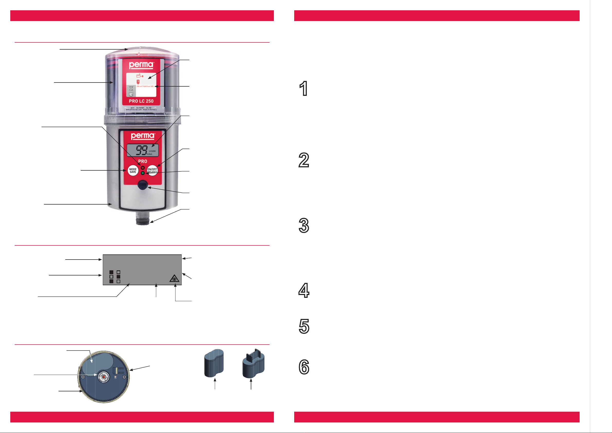
Display
Drive Unit
Protection cover
With bayonet catch for quick
opening/closing.
.
PRO LC-Unit
(Lubrication Canister)
Cartridge, piston, spindle
lled with lubricant.
Red LED
Additional malfunction
indication.
Push Button: MODE/SAVE
Leads to the
Conguration Menu and saves
the selected settings.
Drive Unit
Contains electronics,
motor, and pump system.
Content
Description of the lling date and the
contained lubricant.
Type
Product type and size of PRO LC-unit.
Display
Informs about operating conditions,
malfunctions, settings, and the
lubricant volume left in the
PRO LC-unit.
Push Button: ON/OFF/SELECT
To turn system ON or OFF and to
change settings.
Green LED
Additional indication of the current
operating condition.
Connector for distributor
PRO MP-6
Connection thread
G 3/8 outside and G 1/8 inside for ap-
plication into a lubrication point or for
connecting a grease tube.
Conguration menu
For entering the settings.
Outlets 1 - 6
Shows activated outlets
Number
Shows remaining volume,
discharge period, outlet no.,
PIN, and malfunction codes.
Setting Mode
Displays the current setting in days,
weeks, or months.
Size of PRO LC-unit
Displays volume of LC-unit
(250 or 500 cc)
Ice icon
Indicates either that the temperature
fell below 0 °C/32 °F (icon blinking),
or that the low temperature shutoff
(below - 20 °C/- 4 °F) has turned the
system off (icon permanent).
Battery Compartment
For insertion of battery
set
Catch
For driving the spindle
Interlocking Teeth
To position the
PRO LC-unit.
No function! Setting of
PRO LC-unit size is done
via menu on the display.
Battery-Set
(PRO B)
Battery-Set
(PRO B PLUS)
Quick Reference Guide for the Lubrication System perma PRO
On this page you will nd some important information for quick and easy operation and setting of the perma PRO. Before
the rst installation of the perma PRO, and whenever you need detailed instructions, you should read the complete
Operating Manual which contains information that must be observed. Make sure to follow the instructions given in the
chapter “Safety Notes”.
Lubrication System perma PRO
Remaining volume
of the PRO LC-unit
Shows the lubricant
remaining in the PRO
LC-unit in % volume.


