Disclaimer: Relationshipware LLC and its members are NOT
RESPONSIBLE for any injury or loss of property to any
person suffered while operating this water rocket launcher.
*** If the bottle fails to release from the launcher or it is aimed in an
unsafe direction and you are exceeding 120 PSI, then ABORT your
launch. Carefully pull the safety valve ring to release the air pressure
within the bottle; than one can remove the bottle from the launcher.
StratoLauncher®IV Launch Instructions
Please read operating instructions carefully before launching
any plastic bottles. Designed for ages 10 and over. Operate
launcher with extreme care and only under adult supervision.
WARNING: Do NOT allow anyone to touch the bottle after pumping has
begun. Do NOT aim the bottle at anyone or any other object, either public
or private. Do NOT stand over the bottle. Do NOT impact the bottle under
pressure as it may shatter. Do NOT exceed 120 PSI inside the bottle.
Safe & Secure
Choose a safe area such as a huge field or
park away from people, trees, and resi-
dences to launch plastic bottles (rockets).
Although no pulling action against the
launcher is required to release the rocket,
securing the base with 1 or 2 tent pegs
(not included) may help avoid accidental
tip over during use.
Launcher supports most .5L, 1L, 1.25L and
2 liter plastic (PET*) bottles.
Mount Rocket
Tilt the entire launcher to the side, parallel
with the ground, and slide the bottle over
the 1/4" SS tube. Press the bottle against
the Q-Release hose connector until it locks
with a loud click. Place the launcher on the
ground and secure with tent pegs if de-
sired. Alternate method: hold your finger
over the nozzle and place the bottle above
the 1/4" SS tube, then rapidly remove your
finger and push the bottle over and down
the tube and lock in the hose connector.
Prepare Trigger
Fully stretch out the brake cable on the left
side of the launcher parallel with the tank
valve. Insert the black cable housing into
the manifold cable stop, push Q-Release
hose connector down & place nipple into
clamp-on cable stop. Remove any excess
cable slack with brake lever adjustments.
* Polyethylene terephthalate (aka PET) is a thermo-
plastic polymer resin of the polyester family that is
used in soda pop bottles. Serious bodily injury could
result from using any other type of bottle.
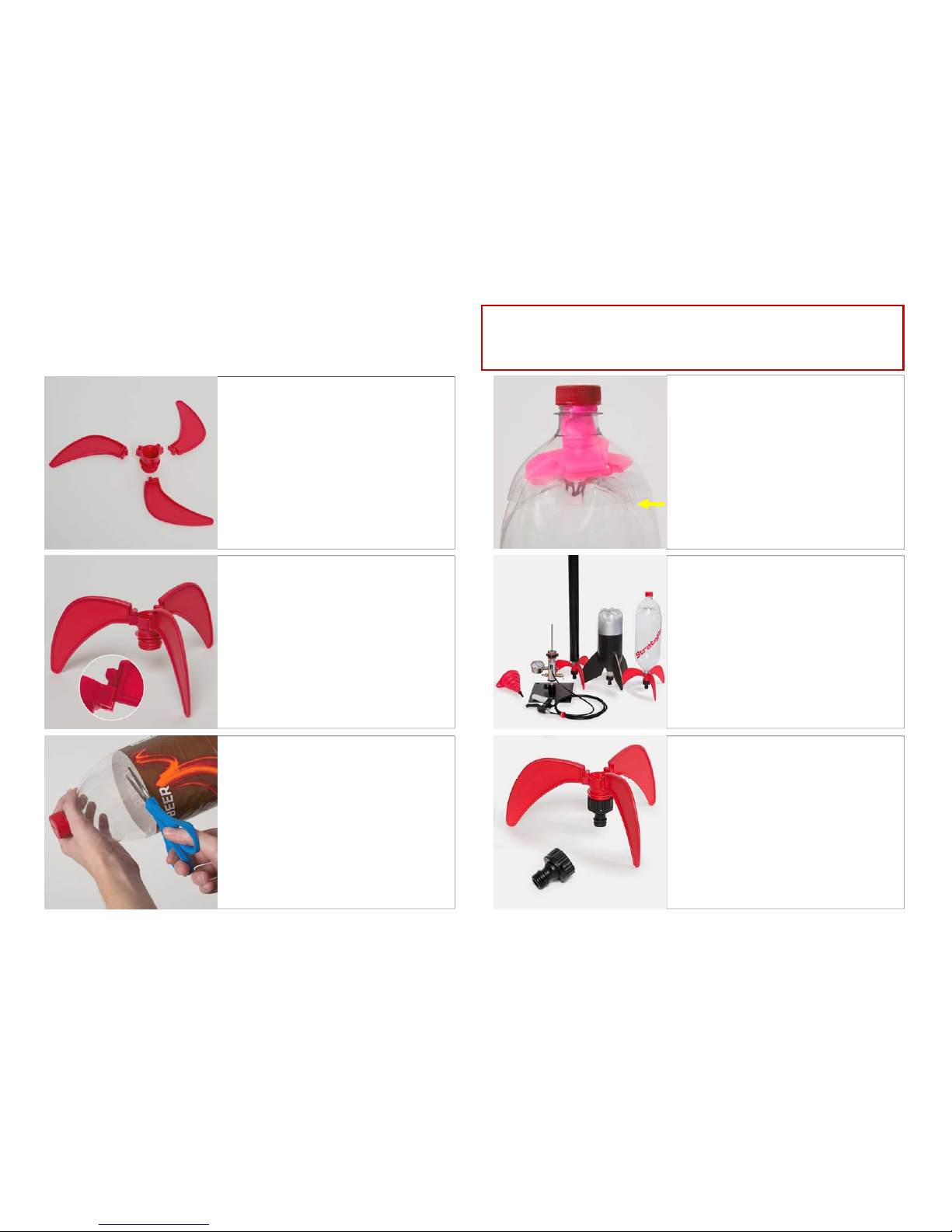
Funnel Fill
Inspect your PET* bottle for any damage
or potential problems. If in doubt discard
the bottle and employ another.
Use only water and/or air for fuel.
Insert the red funnel into the bottle & fill the
funnel to the brim quickly and stop pouring.
This will yield the ideal amount of 1 cup
(notice the water level near the score mark
on the 1/4" SS tube when the bottle is
mounted on the launcher).
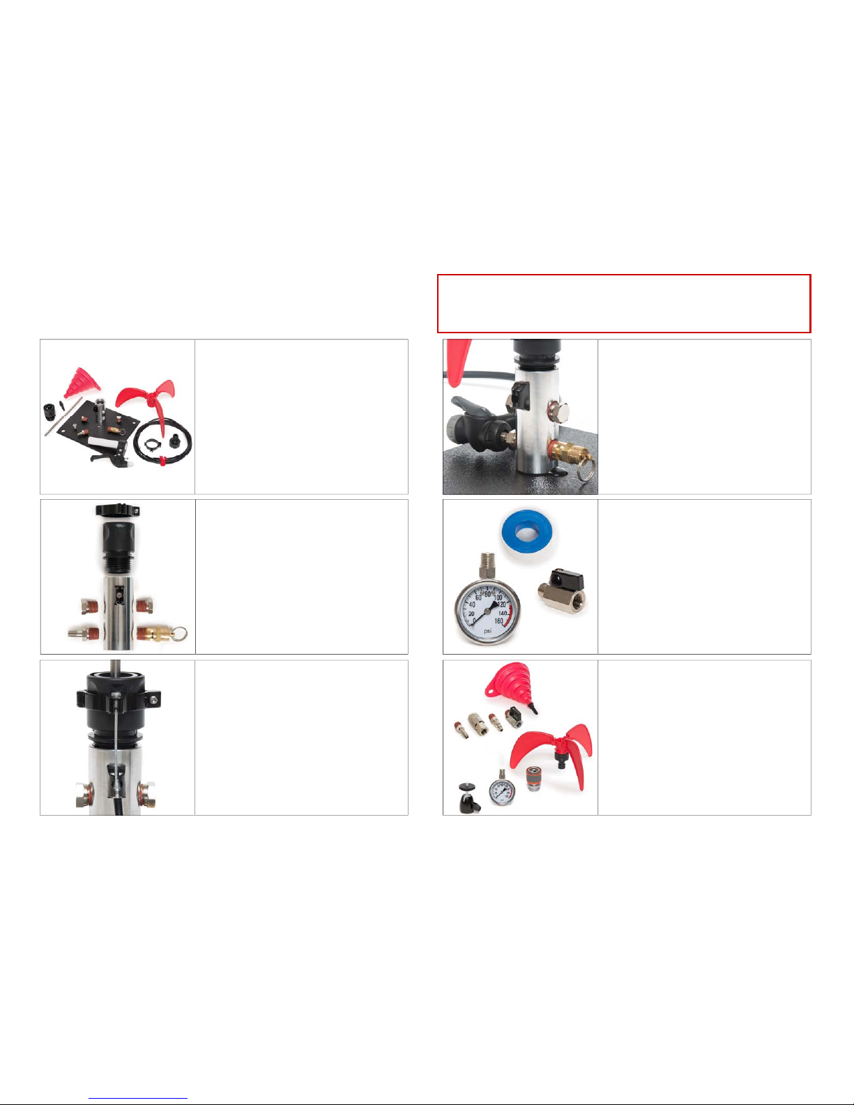
Water Fill Upgrade Kit
StratoLauncher IV Ultimate kit contains an
upgrade kit that can be purchased sepa-
rately, which enables the use of a tank
sprayer (available at local hardware stores)
as your water fill source. A 2 gal. tank will
yield about 30 launches. Pressurize the
tank by pumping 10 or more times. Open
the mini ball valve on the launcher until the
water level touches the score mark on the
1/4" SS tube, and then close for efficient
and spill free fueling.
Pump & Launch
Attach the air source** to the Schrader
valve on the launcher. Be sure all persons
are at least 10 feet away from the
launcher, then begin pumping. Launcher
supports air pressures between 10 PSI up
to 120 PSI***. Stop pumping once you
achieve the PSI that you desire. Place
nose cone on rocket. Squeeze the brake
lever from a safe distance and out of the
splash zone to launch the rocket. Enjoy!
** Sources for compressed air include a bicycle pump,
a foot pump for a car, scuba tank, or air compressor.
1
2
3
4
5
6
Copyright © 2017 by Relationshipware LLC