2www.relax-a-mist.com1-800-Y-U-STEAM (1-800-987-8326)
INSTALLATION INSTRUCTIONS - CR-12 & CR-14, 3PH
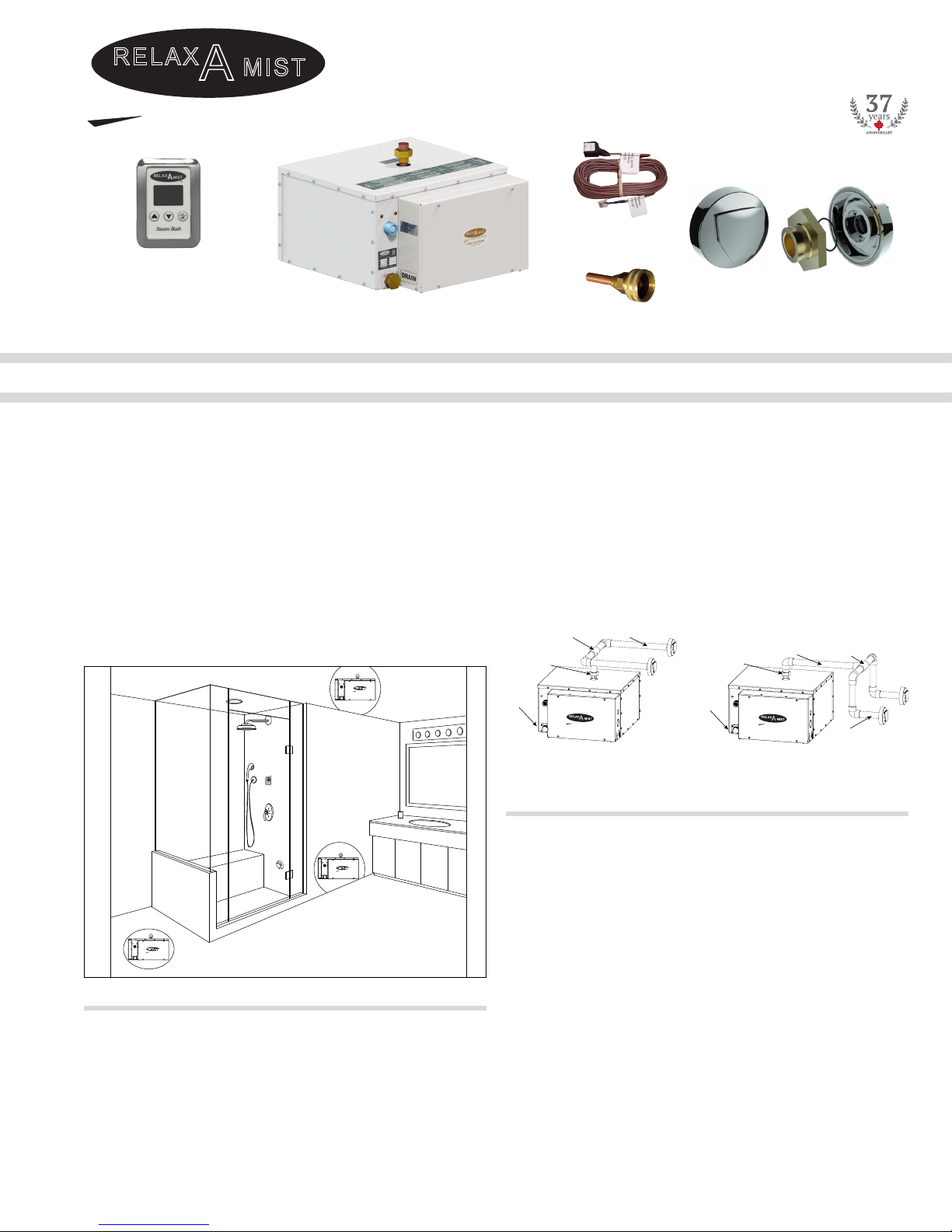
2. ROUGH-IN
WATER SUPPLY (According to Local Plumbing Code)
a water hammer arrester (water bumper) is recommended.
To maintain a proper water level in the generator, the water
corrode the steam generator, install appropriate water treatment.
See CAUTION 4 and Warranty Policy. See diagrams on Page 6.
DRAIN VALVE OPTION (According to Local Plumbing Code)
A 3/4 inch rigid copper pipe must be installed from
ELECTRICAL - WATTS, WIRE AND FUSE SIZES
(According to Local Electrical Code - Use Copper Wire Only -
Must be Installed by a Qualied Electrician)
circuit breaker must be of adequate size to carry the
necessary amperage to operate the steam generator.
away from the area above the steam diusers), to install the
Quick Touch Timer (found in the appliance electrical box), and
wall material and pass the female end of the cord set through
OR, the Time and Temperature
purchased separately).
There is one class 1, 3 conductor copper wire and
ground power cable, and one, factory supplied, class 2
25 foot control wire to be run to the steam generator:
a) Run a copper power supply cable, 3 wire
and ground, of adequate gauge to carry the
necessary amperage from the fuse or circuit
ELECTRICAL SUPPLY & PIPING
See CAUTION 8-10.
SUPPLYCANNOT
Use Copper Supply Wire Only.
The copper power supply cable must run directly from the fuse
or circuit breaker to the steam generator. The factory supplied
cord set must be run directly from the steam generator to
in the steam generator, through the class 2 voltage circuitry.
STEAM PIPING TO BATH OR SHOWER
from the steam generator to where it will enter the steam
WARNING: STEAM DIFFUSERS ARE HOT AND CAN CAUSE
SEVERE BURNS. LIVE STEAM IS 212 °F (100 °C).
The 3/4” end of the steam pipes at the steam room should have
IMPORTANT - Ensure the
elbows are perpendicular to the nished wall on two axis.
Check their orientaon by threading in a nipple that extends
past the studs and out beyond the nished wall. This way
4 turns), so it will protrude through the wall into the steam
nipples will be replaced by brass nipples of the appropriate
length. See Final Installaon Steam Piping and Fig. 3.
STEAM GENERATOR: CR-12 CR-14
208 VOLTS
*
o
Fig. 3
1- Steam diuser
2 - O-ring
3 - 3/4” C x FIP adapter
4 - Sealer (silicone)
5 - Finished wall
6 - 3/4” brass nipple
7 - 3/4” C x C wing-back
elbow
8 - 3/4” copper pipe type “L”
9 - 12” from steam pipe to
steam room oor.
15 3 2
4
678
9
WARNING: STEAM DIFFUSERS ARE HOT AND CAN CAUSE
SEVERE BURNS.