Relcross 9130 User manual

InstallationInstructions
RelcrossLtd
9130/9140
LowEnergySwingDoor
AutomaticOperator

1
CONTENTS
1GENERAL 2
2PRE-INSTALLATION &PRODUCT CHECK 3
3OPERATOR INSTALLATION 4
4WIRING 5
5ARM&COVERINSTALLATION 6
6OPERATOR ADJUSTMENT 7
7FUNCTION TABLES&WIRINGDIAGRAMS 10
8RELEASE FORSERVICE 15

2
1 GENERAL
The Relcross 9130/9140 is anautomaticelectromechanicalswingdooroperator
for useon hinged,centre pivoted,andoffsetpivoted doors.The controller isa
microprocessorbasedsystem,trackingthedoorpositionat anytimeduring
the cycle.When activated theRelcross9130/9140 drives the doortothefull
open
pos
ition creating the potential energyinthespring.Whenclosingthe
electricalpowerisreduced andthe doorclosesbycontrollingthepotential
energy releaseinthespring force.Theactivating circuitopensthedoor
fromanypositionontheclosingswing.DuringpowerfailuretheRelcross
9130/9140acts asamanualdoorcloser(size3).Dooropeningand closing
cycles,including openingspeed,back check speed,holdopentimedelay,
closingspeed, andlatchpositionareadjustable.
CAUTION
Alwaysdisconnectmainpowertothe
operatorprior toservicing orcleaning
Warning
.
CAUTION

3
2 PRE-INSTALLATION&PRODUCTCHECK
2.1Checkthat the product modeliscorrectforthe required application.
2.2Checkthatall partslisted for theinstallation arereceived.
2.3Checkarchitecturaldrawingsand finalapproved shopdrawingsfor position
offrameandstructural openings.
2.4Checkheaderandframedimensionsandrequired clearances(seebelow).
2.5Ensuredoorweightsislessthan 90Kgsfor heavierdoors,consult supplier.
2.6 Check thata240 Volt,singlephase,50 Hz,fused supply(5ampfuse
maximum)isavailableatthesideofthe jambwithinapproximately1
Meteroftheheader.Approved type conduitisrecommended for240V
systems.
2.7Ifanelectriclockistobeconnected tothesystemthe maximumcurrent
drawis2Amps.Theswitching relaycontactisamaximumresistivecurrent
of2Amps.
2.8Thesupplymustbe adedicated circuitfromthe maincircuitbreakerpanel
and mustnotbe connectedintobuildinglightingcircuitwithfluorescent
lights.
2.9WhenPre-Install&ProductCheckiscompletegoto 3OPERATOR
INSTALLATION.
Clearances for PullSystem Clearancesfor PushSystem

4
3 OPERATORINSTALLATION
3.1Removecontrolboxthen motorfromtheir mounting brackets.
3.2Prepareheaderframeforpushor pull system(seebelow).
3.3Install operator-mounting bracket ontotheheader/frame.
3.4Re-install motor then controlbox ontotheir mounting brackets.
3.5Whenoperatorinstallation iscompletegoto 4WIRING.
HeaderFrame&DoorPreparation: Push System
REVEAL
DIMA: ForButt-HungorOffsetPivot DIMA: ForCentrePivot
25mm 559mm 686mm
51mm 533mm 660mm
76mm 508mm 635mm
102mm 483mm 610mm
127mm 457mm 584mm
152mm 457mm 584mm
NOTE:Forpushunits witharevealgreaterthan152mmyouwill needtopurchase an
extendedarmandreferto installationsheetincluded
HeaderFrame&DoorPreparation: PullSystem

5
4 WIRING
CAUTION
Make sureallwiresareproperlydressed andsecured to
prevent interference
Routeall wiring awayfrommovingparts,sharpedges,
and heatsources
Use copper conductorsonly
Do notmodifythe factorywiringor connectintoexisting
electricalcircuitsordevices
4.1Refertothe appropriatewiring diagramforthestandardcontrolbox(Page
22)orthe diagramsupplied forcustomapplications.And connectthe
followingcables:
-Ground cable(groundthe operatorproperlywiththe earthfrommain
supply)
-Halleffectcable(donotwrap the hall effectcablearoundthe motor
cable)
-Motorpowercable(do notwrap the motorcablearoundthehall-effect
cable).
-Controlbox powercable
4.2Connectactivation andsafetydevices +operationalkeyswitchand lock
accessories ifapplicable.Refertotheaccessoryinstruction sforany
accessories used.Do notconnectanyremoteactivating device tothe door
unlessitislocated withinline ofsightofthedoor.
4.3Whenwiringiscompletegoto 5ARM &COVER INSTALLATION.
C
TION

6
5 ARM&COVERINSTALLATION
CAUTION
Keep hands, clothing, wires, tools, etc. awayfromthe
operatormotorwhenthe operatoristurnedon
5.1Make suretheoperatorpowerswitch isturnedOFF.
5.2Install ajumperacrossthe control box MAINACTT28 and COMMONT27.
5.3Turntheoperatorpowerswitch on.The operatormotorwill activateand
drivetothe full openposition.
5.4Attachthe armtotheoperatorspindlelooselywiththe 8-mm sockethead
screw(forpushsystemsensureadjustingbossisinsertedcorrectly).
5.5Attachthearmtothedoor:
5.5.1Forpushsystemsattach thepush armshoe tothe door.
5.5.2Forpullsystems,slidethe pull armrollerintothe track,insertatrack
cap oneachendofthetrack,and attachthe tracktothedoor.
Push Arm Pull Arm
5.6Adjust thearm:
5.6.1Forpull systems,removethe lockingscrewfromthe arm.
5.6.2Forthe pushsystemremovethelocking screw fromthe arm.
5.6.3Keep the doorinthefull open position and adjustthe armlengthas
necessarytoalign thedoorat90degrees fromclosed. When the arm
isadjusted tothe correctlength,tightenupthe8mmsockethead
screwthatsecuresthearmtotheoperatorspindle(ensurethisis
secure)and thentightenthearmlocking screw.
5.7Turnoffthepower operatorswitch - the door closes.
5.8Removethejumperfromthe control boxT27, T28.
5.9Whenarminstallation iscompletegoto 6OPERATOR ADJUSTMENT

7
6 OPERATORADJUSTMENT
CAUTION
Iftheencoderisconnected intheoppositedirection,disconnected
orfaultythedoorwill operateerratically(continuouslyopening
halfway,closing,latching and reopeningetc.).Thiswillcontinue
untilpowerisswitchedoff andproblemrectified.
6.1 SETTINGFUNCTION
6.1.1Fromthe FUNCTIONSELECTOR switch toone ofthe 6standard
programsettingsdependingon the desiredfirealarmposition AND
monitored safetyrequirement(see FUNCTION tableonpage11).If
no safetydevices aretobe usedthenonlythe firealarmposition is
critical.
6.1.2Forfunction 0,3&6(i.e.failsafetoopenposition)FireAlarminput
operates the doorandit remains inthe openpositionforaslongas
thecontactismade.
6.1.3Forfunction 1,4&7(i.e.failsafetoclosedposition)FireAlarminput
disablesall activationallowingthedoortoclose whereitremains for
as long as the contactismade.
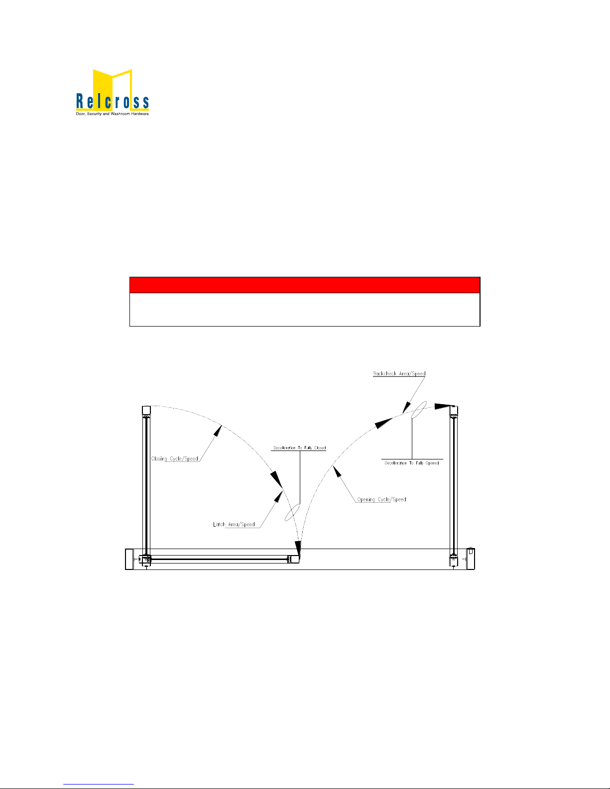
6.2 LEARNINGCYCLE& SETUP(no safetysensors)
6.2.1Fromstart-up,thedoorwillactivatefromeitherT9 &T10(FireAlarm)
orT27&T28 (OneWay).Activatethe operatorusingthe activation
device -the operatorwillperformone learningcycle.Duringthe
learning cycle,the dooropensand closesonetime.
6.2.2Thespeedofthe learning cycleisadjusted automaticallyto
compensateforthedoorweightand isnotsetfromapotentiometer.
6.2.3Thedoordrives tothefullyopen positionwherethecontrolboxsets
theparameterstothefullyopen setting(NB -remembertoinstall
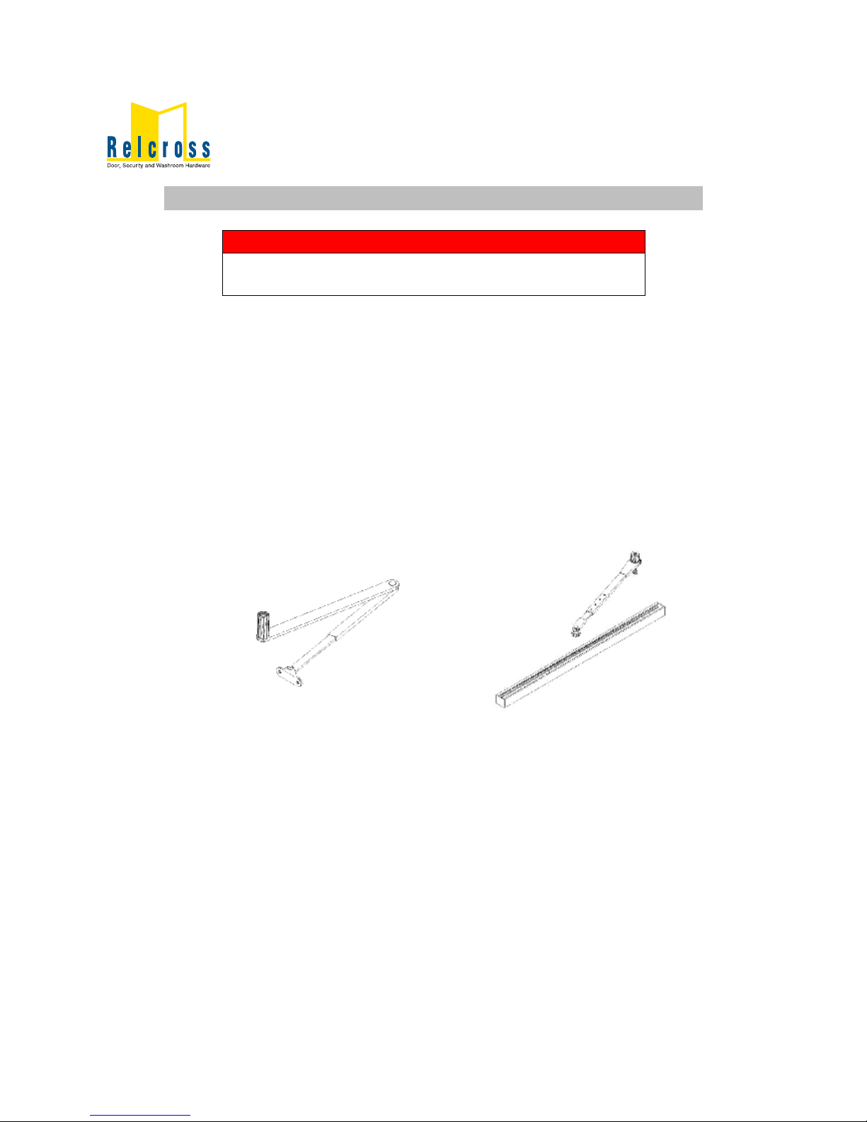
drive armwhendoorisinthe openposition).
6.2.4When the doorreaches the fullyopen position thecontrolbox
automaticallysetsthe powerrequired tokeep thedooropenuntil
activation and/ortimer iscleared
6.2.5Thedoorclosesatthe designatedclosespeed(P6)uptolatch
position(P5)wherethe speedisdecreased automaticallybythe
controlboxallowing thedoortoclosesmoothlyuntil fullyclosed.
6.2.6If thedoordoesnotopen atall duringlearning cycle:
-Checkthedoor forbinding.

8
-Ifan electromechanicallockisbeing used,checkthat thelock
disengagesbeforethe operatoropens the door.
-Checkfuses,circuitbreakersand connections.
-Adjustthe operator andcheckdooroperation.
Opening speed75%
Back checkspeed 75%
Holdopen timedelay Minimum
Latch positionMaximum
Closingspeed 50%
SW1,2,3,4OFF
6.2.7If thedoordoesnotopen fullyduringlearningcycle:
-Checkthedoor forbinding.
-Increasethe back-checkspeedslightlyand check door
operation.Continue increasingback-check speeduntildoor
opens fully.
6.2.8If the doorslamsopendecreasethebackcheck speedslightly(P2)
andcheck dooroperation.Continue decreasing backcheckspeed
until thedooropens withoutslamming.
6.2.9Afterthe learning cycleiscompleteand thedoorisclosed,applya
maintainedactivation signalandcheckthatthe doorremains open
whilethe signalisapplied.
6.3 AUTOREVERSE
6.3.1Thedoorwillautoreversebacktotheopen ifanobstructionis
present
6.3.2P4setstheleveloftorque required totripthedooras itisopeningso
thatit automaticallyrevertstotheclosedposition
6.4 SAFETYSENSORS
6.4.1DoorSafetyOpening:
Firstly,when thedoorisinthe closed position,activatethe safety
device (T1 &T2)then trytoactivatethedoor.Thedoorshouldremain
closed
Secondly,activatethe doorand as it isopening activatethe safety
device.Thedoorshouldstop andthen slowlydrive tothe fully
openingposition
Thepointatwhichthe safetydevice becomesinactivecan be
adjusted viaP8 fromclosed positionuptoback checkposition

9
6.4.2DoorSafetyClosing:
Firstly,activatethe doortothefullopen position thenactivatethe
safetydevice(T5&T6).The doorshouldremainopen.
Secondly,activatethedoorandasitiscloses activatethe safety
device.Thedoorshouldstop and then re-openslowlytothefully
openposition,timeout andclose.
Thepointatwhich thesafetydevice becomes inactivecan be
adjusted viaP7 fromopenposition uptoafewdegrees ofclosed
position
NOTE
Adjustoperatorinaccordance withEN16005 beitforpower assisted
lowenergypower operateddoors

10
7 FUNCTIONTABLES &WIRINGDIAGRAMS
See tableanddiagramsthatfollow foroperatorfeatureselection and
adjustments.Afteradjustment, cyclethe doorseveraltimesand checkforproper
operation.Thengoto 8RELEASE FOR SERVIVE.
N
7.1CONTROLBOX:POTENTIOMETERS& SWITCHES
7.4OTE
ON OFF
POWERBOOST ADJ
CONT 5SECS SW4
POWERBOOST ACT
ON OFF SW3
PUSH&GO
ON OFF SW2
MONITORED SAFETY
ON OFF SW1

11
7.2CONTROLBOX:FUNCTIONS
FUNCT.PROGRAMDESCRIPTION MONITORINGTERMINALOPERATION
0Standard
Standard functionalityand
adjustment-doortofailsafeopen on
fire alarm
Safety:Opening &
Closing
T1, T2DoorSafetyOpening
T5, T6DoorSafetyClosing
T9, T10Fire Alarm
1Fire Alarm
Standard functionalityand
adjustment-doortofailsafeclosed
on fire alarm and remainelectrically
unlocked(iflocking present)
T27, T28One Way
T14DoorOpen
T12KeySwitchOff
2WC BESPOKE SOLUTION-RELCROSS T22, T23TwoWay
3Standard
Standard functionalityand
adjustment-doortofailsafeopen on
fire alarm
Safety:Opening
Only
T1, T2DoorSafetyOpening
T5, T6DoorSafetyClosing
T9, T10Fire Alarm
4Fire Alarm
Standard functionalityand
adjustment-doortofailsafeclosed
on fire alarm and remainelectrically
unlocked(iflocking present)
T27, T28One Way
T14DoorOpen
T12KeySwitchOff
5WC BESPOKE SOLUTION-RELCROSS T22, T23TwoWay
6Standard
Standard functionalityand
adjustment-doortofailsafeopen on
fire alarm
Safety:Closing
Only
T1, T2DoorSafetyOpening
T5, T6DoorSafetyClosing
T9, T10Fire Alarm
7Fire Alarm
Standard functionalityand
adjustment-doortofailsafeclosed
on fire alarm and remainelectrically
unlocked(iflocking present)
T27, T28One Way
T14DoorOpen
T12KeySwitchOff
8WC BESPOKE SOLUTION-RELCROSS T22, T23TwoWay
9, A-F
NOTINUSE
A
B
C
D
E
F

12
7.3CONTROLBOX:SETTINGS
Features ControlDescription Anti-Clockwise Clockwise
Opening
Speed P1Controlsopening speedof door Slower Faster
BackCheck
Speed P2 Controlsspeed ofdoornearfullopen
positionprevent doorslamming Slower Faster
Hold Open
TimeDelay P3 Controlslengthoftimedoorremains
inthefull openposition
Lesstime
(min1sec)
Moretime
(max30sec)
AutoReverse
Setting P4 Setspressurerequired ondoor
opening beforedoorstops
Lesspressure
required
Morepressure
Required
Latch
Position P5
Distanceatwhichthedoorbeginsto
deceleratetofullyclosed position to
preventdoorslamming
LesslatchMorelatch
Closing
Speed P6Controlsclosing speedofdoor Slower Faster
Safety
Opening
Angle
P7 Controlsthe angle duringtheopen
cyclethatsafetyoperates
Closertoclosed
position
Furtherfrom
closedposition
Safety
Closing
Angle
P8 Controlstheangle during theclose
cyclethatsafetyoperates
Closertoopen
position
Furtherfrom
openposition
Monitored
Safety SW1Toallowmonitoring of safetysensors Monitoring
‘ON’
Monitoring
‘OFF’
Push&GoSW2
Pushingthedooropenby 5°causes
theoperatortoopen fortheremainder
ofthe open cycle
Push&Go
‘ON’
Push&Go
‘OFF’
PowerBoost
Activation SW3
Powerboostgivesaforceinthe
closeddirection when thedooris
closed-used forhigh windsituations
PowerBoost
‘ON’
PowerBoost
‘OFF’
PowerBoost
Adjustment SW4
Enablespowerboosttooperate
continuously orfor5secondsonly
afterthe doorcloses
Continuous5Seconds

13
7.4WIRINGDIAGRAMINCLUDINGTERMINALS

14
7.5TERMINALS(CLOSE UP)

15
è ÎÛÔÛßÍÛÚÑÎÍÛÎÊ×ÝÛ
8.1Snap theoptionalendcap insertintotheend cap oppositethe on/off
switch.
8.2Install the coverassemblyontothe operator.
8.3Removeall installation equipment and debrisfromthe vicinityofthedoor.
8.4Installall safety,trafficcontrolandinstruction labelson the dooras
required underEN16005.Failuretodothisleavesthe installerLIABLE for
anyaccidentthat might occur- thismustbedone.
8.5Instructthe owneror person inchargeoftheproperoperation of thedoor.
8.6Instructtheownerorperson inchargetoroutinelyinspectthe doorforthe
following:
-Occasionaldamage
-Developingproblems
-Minorpreventativemaintenance
8.7Instructtheownerorpeopleinchargewhoand wheretocallforservice
and maintenancewhen required.
×ÓÐÑÎÌ
×ÓÐÑÎÌßÒÌ
·²-¬®«½¬·±²¼»½¿´-±²¬¸» ¼±±®¿-®»¯«·®»¼
Other manuals for 9130
1
This manual suits for next models
1
Other Relcross Door Opening System manuals
Popular Door Opening System manuals by other brands

Synergy Hardware
Synergy Hardware S500 Series Fixing instructions

GEZE
GEZE Slimdrive EMD Replacement instructions

Dorma
Dorma 8916 FT manual

Stanley
Stanley Dura-Glide 2000AG Series Installation Instructions, Quick Reference Guide

Dormakaba
Dormakaba ED50 installation instructions

Roger Technology
Roger Technology SMARTY Series INSTRUCTIONS AND RECOMMENDATIONS FOR THE INSTALLER