Nerival NEO-100 User manual


2 www.nerival.fi
Table of contents
Safety instructions .....................................................................................................3
Overview....................................................................................................................4
Technical information ................................................................................................5
Installation example...................................................................................................6
Installation of mounting plate and door operator...................................................6
Outward opening door: Installation with push arm (door operator inside) ............7
Inward opening door: Installation with pull arm (door operator inside) .................8
Kytkentä.....................................................................................................................9
Button functions ......................................................................................................11
Settings ....................................................................................................................12
General settings 1-22............................................................................................12
Advanced settings................................................................................................. 13
Kauko-ohjaimen toiminnot ......................................................................................14
Adding a remote control.......................................................................................14
Deleting remote controls......................................................................................14
Digital display code table .........................................................................................15

3 www.nerival.fi
Safety instructions
This manual is intended for use by electrical professionals. All installation
connections and adjustments must be made in accordance with this instruction
manual.
•Before installation
Check for transport damages, do not install / use a damaged unit.
Make sure that the strength and stability of the wall and door structures are
sufficient.
•Connection
Only professional electricians are allowed to make electrical connections.
Make sure the power supply is turned off before making any connections.
This product must be earthed.
•Before turning on the power
Ensure correct supply voltage 230VAC.
Make sure that the input and output connections are connected correctly,
and the connectors are tight. Improper connection can damage the door
operator.
•Always switch off the power before installation or maintenance
and make sure that power is disconnected.
Read the manual carefully before installing the product.
Improper installation can be fatal.
The manufacturer or distributor is not responsible for the
consequences of incorrect installation or use.

5 www.nerival.fi
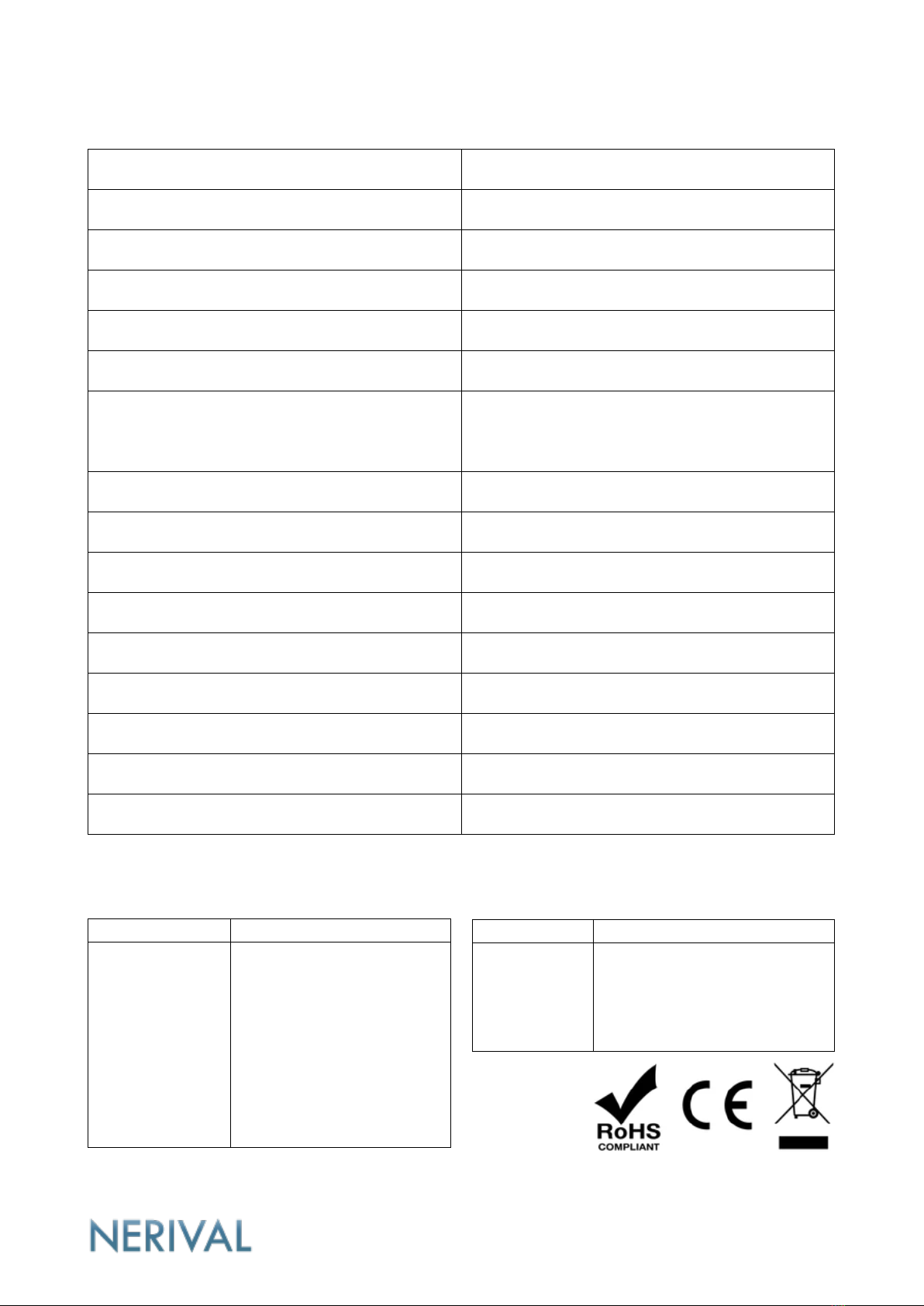
Technical information
Model
NEO-1000
Door max. weight
100kg
Door max. width
1200mm
Weight
6kg
Service life
More than 3.000.000 operations
Installation method
Surface mounting
Voltage output for locking
12VDC
With included relay card
12V AC/DC - 30V AC/DC
Door hold-open time
0-99s, adjustable
Opening angle
45°-180°, adjustable
Supply voltage
230VAC
Max. power
45W
Standby power consumption
< 2W
Remote control distance
Over 30m
Operating temperature
-40℃- 85℃
Protection class
IP41
Dimensions
580mm x 80mm x 90mm
Approvals
EU Directive
Test Standard(s)
2011/65/EU
(RoHs)
EN 62321-1:2013
EN 62321-2:2014
EN 62321-3-1:2014
EN 62321-4:2014+A1:2017
EN 62321-5:2014
EN 62321-6:2015
EN 62321-7-1:2015
EN 62321-7-2:2017
EN 62321-8:2017
EU Directive
Test Standard(s)
2014/30/EU
(EMC)
EN IEC 61000-6-1:2019
EN 61000-6-3:2007/A1:2011
/AC:2012


9 www.nerival.fi
Kytkentä
NO
NO, connected when the door is open
COM
COM
NC
NC, connected when the door is closed
L+
Electric lock output +12VDC*
L-
Electric lock output -12VDC*
GND
Voltage output -12VDC
12V
Voltage output +12VDC, max 500mA
P1+
Voltage signal 12VDC
GND
GND
P1
Door open signal
P2
Door close signal
P3
Closing door safety sensor input
P4
Opening door safety sensor input
GND
GND
P5
Synchronization of two door operators

10 www.nerival.fi
NO/COM/NC: Potential-free changeover switch.
P1 +: Door open signal from access control. The input is a voltage signal of 12VDC.
P1/GND: Door open signal. Sensor signal.
P2/GND: Door close signal. The door does not open when the signal is active.
P3/GND: Safety sensor for closing door. When the sensor detects, the door opens.
P4/GND: Safety sensor for opening door. When the sensor detects, the door stops.
P5/GND: Synchronization of two door operators. Both door operators operate
simultaneously.
* Use the included relay card if voltage used for locking is other than 12VDC.

11 www.nerival.fi
Button functions
•The door operator has a self-learning process when it is turned on or a new
setting is made. The door operator drives the door in its closing direction and
stops it when the door is closed in the correct position.
If the device cannot detect the correct stop position, the error message "E08"
is displayed.
•If the door closes in the wrong direction, see setting no. 9.
•To skip the self-learning process, press the ▲button to enter the setting
mode.
Option+ : Scroll up the settings
Option- : Scroll down the settings
Parameter- : Increase parameter
Parameter+ : Decrease parameter
Save: Save setting / Exit

12 www.nerival.fi
Settings
Press the ▲button to enter the setting mode.
Use the ▲and ▼buttons to select the setting you want to set.
Press the decrease or increase button to set the desired value.
To save the setting and exit the setting mode, press the button.
General settings 1-22
Setting
number
Function
Setting
range
Factory
setting
Additional information
1
Opening speed
0-30
20
The higher the value, the faster the
door opens
2
Closing speed
0-30
20
The higher the value, the faster the
door closes
3
Opening angle
0-99
20
The higher the value, the larger the
opening angle 45-180 degrees
4
Unlock delay
0-99
0
The lock is released first, after which
the door opens after a set delay of 0-
1 seconds
5
Door hold open time
0-99
1
0-99 seconds opening time after the
door has opened
6
Closing door anti-
collision delay
0-30
10
The smaller the delay, the faster the
door opens in a collision
7
Closing force
0-10
5
The higher the value, the greater the
closing force
8
Lock mode selection
0-4
1
1: The door opens by pushing /
pulling
2: -
3: Magnetic lock
4: Electric bolt lock
9
Opening direction
0-1
0
0: left
1: right
10
Adding a remote
control
0-40
0
see Adding a remote control
Additional controller
[80410] RCT-8100
or [33340] RCT-1224
11
Slow closing angle
0-50
0
The higher the value, the greater the
angle at which the door closes slowly
12
Slow opening angle
0-50
0
The higher the value, the greater the
angle at which the door opens slowly
13
Opening door anti-
collision delay
0-30
10
The lower the delay, the faster the
door stops in a collision
15
Closing speed after
reset
0-20
0
Closing speed after reset
16
*P1+ signal mode
0-1
0
Standard voltage signal input
Lock signal ends
17
*P1, P2 Port function
0-2
0
P1 Automatic switch
P2 Forced off

13 www.nerival.fi
1: P1 normally open
P2 close
2: P1 Point move open-close
18
Motor torque
0-20
20
0: minimum
20: maximum
19
Opening delay
0-85
0
Opening delay for synchronization of
two door operators
21
Restore factory
settings
0-10
0
0: empty
1: resets settings 1-22 settings to
factory defaults
22
Delete the remote
controls
0 or 10
0
0: empty
10: Delete all remote controls
Advanced settings
Press the ▼button for five seconds to enter the advanced setting mode.
Use the ▲and ▼buttons to select the setting you want to set.
Press the decrease or increase button to set the desired value.
To save the setting and exit the setting mode, press the button.
Asetuksen
numero
Toiminto
Asetusalue
Lisätiedot
27
Encoder direction
0-1
0: normal
1: reverse
28
Type of electric lock
0-1
0: power on: locked
1: power off: locked
29
Windproof mode
0-1
0: off
1: windproof
31
Protected mode
0-2
0: Lock release
1: Access control
2: Autoreset
14 www.nerival.fi
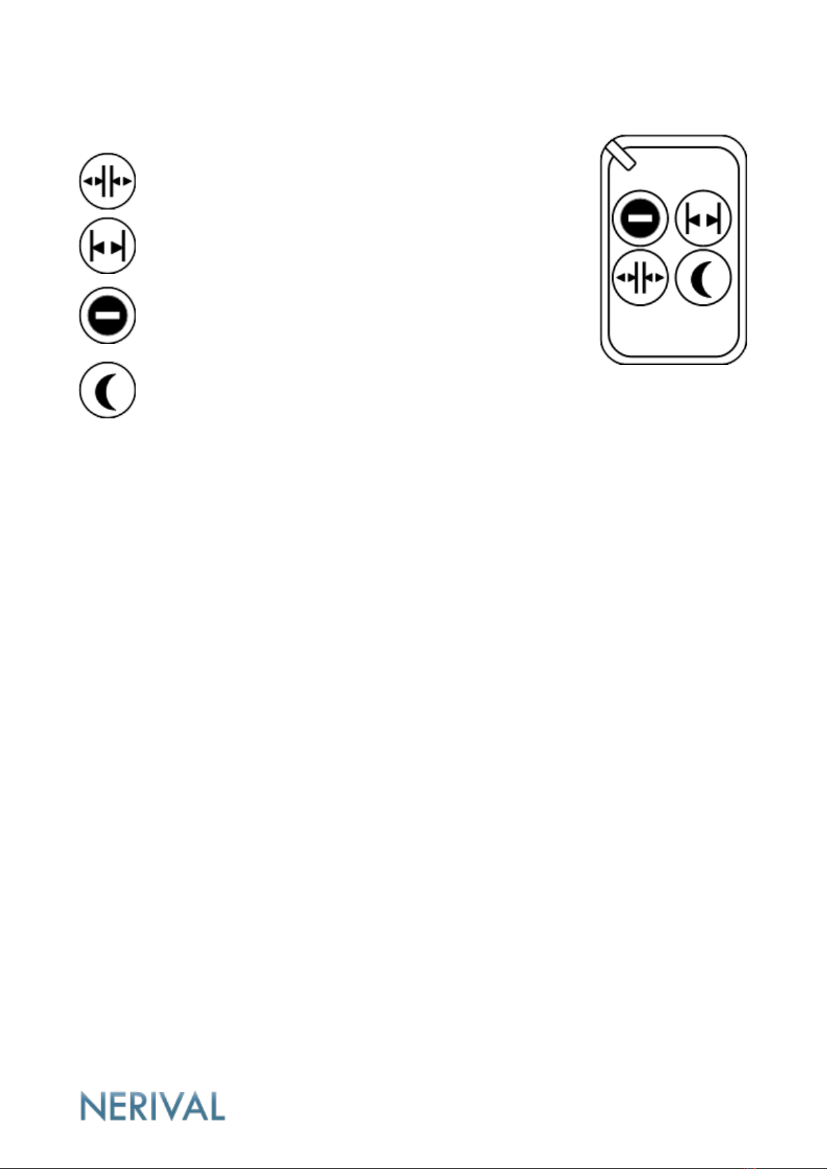
Kauko-ohjaimen toiminnot
Automatic mode. The door opens when the button is
pressed and closes normally.
Hold-open mode. The door opens and stays open.
Not in use.
Sensor and access control signals disabled.
The door can only be controlled with the remote control.
Adding a remote control
1. Go to setting no. 10 and press the parameter increase or decrease button.
2. Press any key on the remote control.
3. The value of the digital display increases by 1.
4. The remote control has been successfully added.
Repeat the above steps to add more remote controls.
Additional controller [80410] Remote control for door operators RCT-8100
or [33340] RCT-1224 Wireless transmitter, 433Mhz (only automatic mode/open
function)
Maximum quantity 40 pcs
Deleting remote controls
1. Got to setting no. 22
2. Set value to 10
3. Press the Save button
4. All the remote controls have been successfully deleted.
15 www.nerival.fi
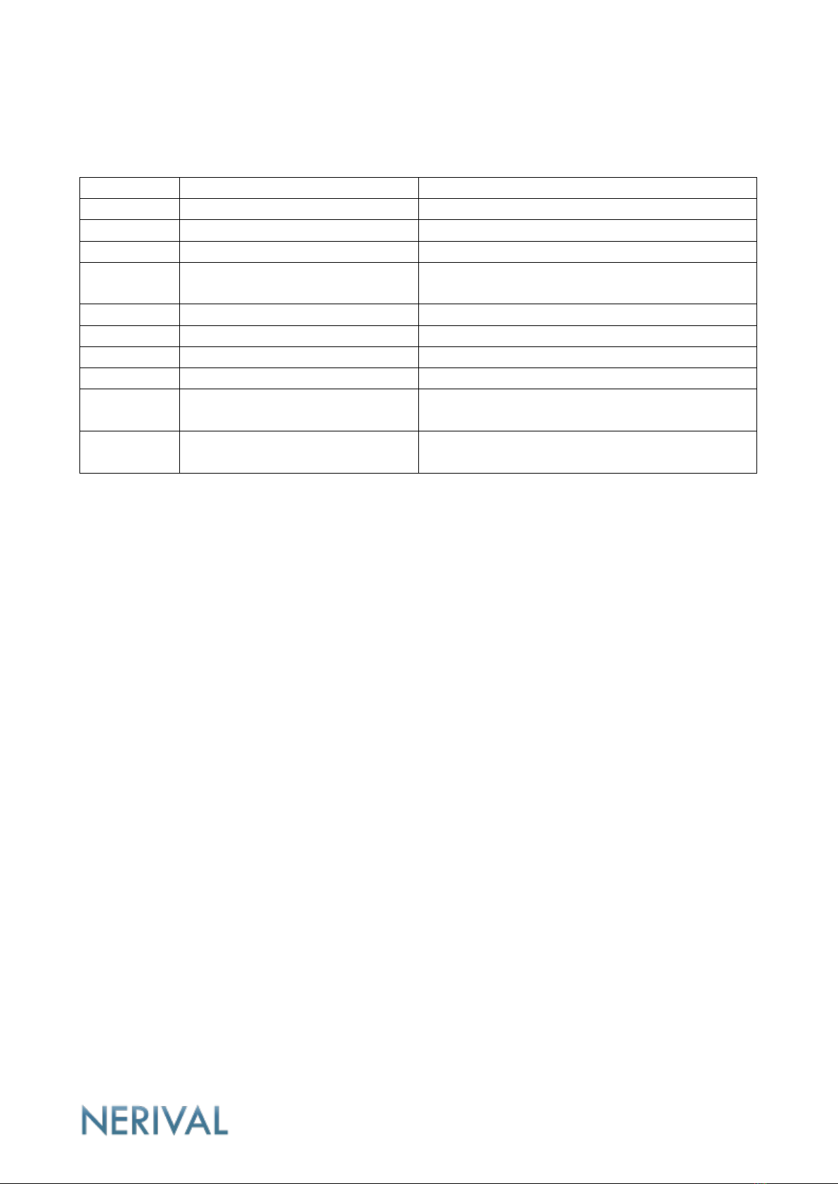
Digital display code table
Error code
Cause
Solution
E0
System error
Replace the controller
E1
The motor is not connected
Check motor connection
E2
Motor line failure
Check motor connection, replace the motor
E3
Electric lock over current
Check that the electric lock is not short-
circuited and the current does not exceed 1A
E4
Too high DC voltage
Check 12V voltage port input and lock
E5
Too low DC voltage
Check 12V voltage port input and lock
E6
Too high AC voltage
Check voltage
E7
Too low AC voltage
Check voltage
E8
No door was detected
Check the attachment of the pull and push
arm
E9
The door does not close
Check the door, remove obstacles in front of
the door
Table of contents
Other Nerival Door Opening System manuals

Popular Door Opening System manuals by other brands

RITE-HITE
RITE-HITE BARRIER GLIDER 7100 manual

Dormakaba
Dormakaba ED900 installation instructions

Yale
Yale 3000 Series installation instructions

Lamp
Lamp AZ-GD231 installation instructions

SUGATSUNE
SUGATSUNE LAMP DC Series installation manual

Assa Abloy
Assa Abloy Norton 1600H Series installation instructions


Assa Abloy
Assa Abloy Sargent Electroguard-59 80 Series Installation and wiring instructions

Smart Standard
Smart Standard SDH-0066-BIGWHEEK-BK manual

Superlift
Superlift RDO-5 Installation instructions and user guide

Falcon
Falcon SC81 installation instructions

gotthard
gotthard smartdoor TURN T100 operating manual

Axema
Axema Vaka B28 manual