10
IMPORIMPOR
IMPORIMPOR
IMPORTT
TT
TANTANT
ANTANT
ANT::
::
: The greatest cause of hydraulic pump failure is dirt.
Prevent the introduction of foreign matter into the unit via hydraulic fluid,
dirty connections or accumulation of sediment.
DAILY MAINTENANCE
The life, reliability, and safety of the tool is dependent on proper maintenance.
Clean all surfaces including head, blade, couplers (if coupled), threads, and handles.
Inspect for wear and damage. Worn or damaged parts may malfunction during operation.
All parts must be replaced with new parts if signs of wear or damage are evident.
Keep Label Set clean and legible. Replace decals when necessary. Part #RL23400
BEFORE USING THIS PRODUCT
READ THE SAFETY WARNINGS
and recommended practices described in
the manual. Failure by the operator to read
and fully understand the warnings will
leave this person unqualified to use and
operate the tool.
Failure to observe all warnings and instructions could result
in property damage, severe personal injury, and/or death.
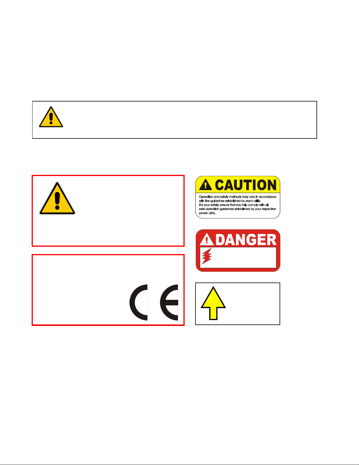
ELECTROCUTION
HAZARD
The user should be properly
trained in the correct procedures
required for work on or around
electrical lines.
REL-SM
WARNING
DD
DD
DANGERANGER
ANGERANGER
ANGER
BLADE
CLOSES
Part # RL20200
NOTE: Keep Label Set clean and legible. Replace decals when necessary.
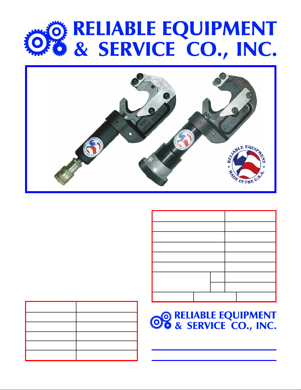
RELIABLE EQUIPMENT & SERVICE CO., INC.
92 Steamwhistle Drive • Ivyland, PA 18974 • USA
Phone: 215-357-3500 • Fax: 215-357-9193
MODEL: PDC-3000
MAX. PRESSURE: 10,000 PSI
SERIAL NO.: ____________
YEAR: ___________
Complete disassembly is not recommended. Return the unit to an authorized dealer
for total disassembly and/or repair.
All maintenance or disassembly should take place on a flat, clean work surface covered
with towels or wipers so as to have a clean space for the disassembled parts.
Inspect each part during disassembly for wear, scratches, and cuts. Discard the worn or
damaged parts and replace with new factory authorized parts.
O-rings are sensitive to sharp edges. Inspect closely for cuts or damage. A small cut will
cause a leak. When assembling or disassembling O-rings, use hydraulic fluid as a
lubricant to help disassembly or installation.