Reliable Equipment 2000 Series Manual

1
DISTRIBUTED BY
OPERATORS’ GUIDE
2000 Series Manual 02-15
WARNING
All information found in this guide
must be read and understood before
use or testing of this tool.
Failure to read and understand these warnings
and safe handling instructions could result in
severe personal injury and or death.
REL-2000SA
SINGLE ACTING HYDRAULIC CUTTING TOOLS
PDC-2000

2
CAUTION
The information in this manual is intended to guide the user
in the use and application of this tool. It is not intended as
a substitute for proper training and experience in safe work
practices for this type of equipment.
Consult your supervisor or safety personnel if you have any
questions regarding the safe operation of this tool.
DISTRIBUTED BY

3
TABLE OF CONTENTS
REGISTRATION
UPON RECEIPT OF THIS TOOL, COMPLETE THE REGISTRATION BELOW.
COMPANY _____________________________________________________________
ADDRESS _____________________________________________________________
________________________________________________________________________
PHONE _______________________ FAX____________________________________
SERIAL NUMBER _______________________________________________________
DATE OF PURCHASE ___________________________________________________
DEALER NAME _________________________________________________________
THIS SYMBOL INDICATES ITEMS OF EXTREME IMPORTANCE.
Safety of user and others may be in jeopardy if these instructions
are not read and understood.
DISTRIBUTOR INFORMATION .................................................. 2
TABLE OF CONTENTS & TOOL REGISTRATION ..................... 3
REL-2000SA - DESCRIPTION & TOOL SPECIFICATIONS ....... 4
PDC-2000 - DESCRIPTION & TOOL SPECIFICATIONS .......... 5
SAFETY INFORMATION AND WARNINGS........................... 6-10
OPERATING INSTRUCTIONS .................................................. 10
DAILY MAINTENANCE & LABELS ........................................... 11
REL-2000SA - PARTS DIAGRAM & PARTS LIST ................ 12-13
PDC-2000 - PARTS DIAGRAM & PARTS LIST.................... 14-15
MAINTENANCE RECORDS & CONTACT INFORMATION ...... 16

4
System Single-Acting
Capacity (Jaw Opening) 2 inch.
Force @ 10,000 psi (690 bar) 28,048 lb.
Max Operating Pressure 10,000 psi (690 bar)
High Pressure Couplers Female Screw Type
Head opens
for cable insertion
along the line.
Weight: 16.5 lb.
Length: 17.5 in.
Width: 6.5 in.
2000 SERIES
MAXIMUM CAPACITY
Soft Copper Jacket 2”
Aluminum Jacket 2”
Communication Cable 2”
ACSR 2”
Wire Rope 1”
Soft Steel Bolts 7/8”
Guy Strand 3/4”
Ground Rod 3/4”
Anchor Bolts 3/4”
Rebar Grade 40 3/4”
REL-2000SA
SINGLE ACTING HYDRAULIC
CUTTING TOOL
301 Ivyland Road • Warminster, PA 18974
Phone: 800-966-3530 • Fax: 215-357-9193
Visit us on the web at www.Reliable-Equip.com
This guillotine style cutter features up to a 2 inch
cutting capacity, 360O rotating head, and a built-
in auxiliary handle.
These cutters can be used for cutting cable,
wire rope, soft steel bolts, guy strand, ground
rods, anchor bolts, and rebar.
The REL-2000SA will make a straight, clean
cut every time.

5
PDC-2000
DOUBLE ACTING HYDRAULIC
CUTTING TOOL
This guillotine style cutter features up to a 2 inch
cutting capacity, 360O rotating head, and a built-
in auxiliary handle.
These cutters can be used for cutting cable, wire
rope, soft steel bolts, guy strand, ground rods,
anchor bolts, and rebar.
The PDC-2000 cuts straight & clean cut every time.
System Double-Acting
Capacity (Jaw Opening) 2 inch.
Force @ 10,000 psi (690 bar) 28,048 lb.
Return @ 5,000 psi (345 bar) 10,445 lb.
Max Operating Pressure 10,000 psi (690 bar)
Max Return Pressure 5,000 psi (345 bar)
Couplers Direct Connect
Head opens
for cable insertion
along the line
Weight: 16.5 lb.
Length: 17.5 in.
Width: 6.5 in.
PDC-2000 SHOWN
PCU-2000 INCLUDES COUPLERS
MAXIMUM CAPACITY
Soft Copper Jacket 2”
Aluminum Jacket 2”
Communication Cable 2”
ACSR 2”
Wire Rope 1”
Soft Steel Bolts 7/8”
Guy Strand 3/4”
Ground Rod 3/4”
Anchor Bolts 3/4”
Rebar Grade 40 3/4”
301 Ivyland Road • Warminster, PA 18974
Phone: 800-966-3530 • Fax: 215-357-9193
Visit us on the web at www.Reliable-Equip.com

6
WARNING
BEFORE USING THIS TOOL, READ THE WARNINGS
and the recommended practices described in this manual.
Failure by the operator to read and fully understand these
warnings will leave this person unqualified to use and
operate this tool. Property damage, severe personal injury,
and/or death could result by not following these warnings.
Eye Protection
These warnings will appear in appropriate locations when they are pertinent to the
particular subject being shown. Read each one carefully and follow them strictly.
WARNING
Always wear eye protection to avoid
injury from flying debris or hydraulic
oil leaks. Failure to do so can result
in serious personal injury.
Hard Hat
WARNING
Always wear a hard hat to avoid injury
from falling debris. Failure to do so
can result in serious personal injury.
Hearing
Protection
WARNING
Always wear hearing protection,
to avoid hearing loss due to long
term exposure to high noise levels.
Foot
Protection
Always wear foot protection.
Failure to do so can result in serious
personal injury.
WARNING
WARNING
Protective
Gloves
Always wear protective gloves
Failure to do so can result in serious
personal injury.
WARNING
Skin
Irritation
Hydraulic oil may cause irritation.
Use care to prevent contact with skin.
In case of accidental contact, wash
affected area immediately

7
WARNING
HYDRAULIC POWER SUPPLY
DO NOT attempt to make any changes to any of the component
parts or accessories when connected to the power source.
DO NOT adjust, inspect, or clean tool while the tool is connected
to the power source. The tool could accidentally start up and
cause serious injury.
DO NOT lock the tool in the On Position. In an emergency,
serious damage or injury could occur during the time required
to stop the tool.
SAFE OPERATION & CARE
USE THIS TOOL FOR ITS INTENDED PURPOSE ONLY
Any other use can result in injury or property damage.
INSPECT TOOL BEFORE USE. Replace any worn, damaged or
missing parts. A damaged or improperly assembled tool may
malfunction, injuring operator and/or nearby personnel.
INSPECT HYDRAULIC HOSES AND COUPLINGS before each
use. Repair or replace if any cracking, leakage, wear or damage
is found. Worn or damaged hoses may fail resulting in personal
injury or property damage.
CLEAR WORK AREA of all bystanders and unnecessary personnel
before operating this tool.
KEEP ALL PARTS OF THE BODY AWAY FROM MOVING PARTS.
Failure to observe this warning could result in serious injury.
WARNING
OIL INJECTION INJURY
Hydraulic oil or fluid under the skin is a serious injury. Oil under
pressure can penetrate the skin and may cause dismemberment
or loss of life. Seek medical assistance immediately if such an
injury should occur.
Always wear safety gloves, eye protection and all required
safety equipment when operating or handling this tool.
DO NOT use fingers or hands to attempt to locate a leak.
DO NOT handle hoses or couplers while system is pressurized.
NEVER open or service the system before depressurizing.
WARNING

8
HOSES AND FITTINGS
There exists the potential for shock in using anything
other than certified nonconductive hoses and hydraulic oil
with dielectric properties, when using system components
near energized electrical lines. Failure to recognize these
conditions could cause electrocution.
Hoses and fittings used with this tool must comply with S.A.E. J1273 which
covers recommended practice for selection, installation, and maintenance of hose and
hose assemblies. The correct hoses and fittings are available from your supplier.
WARNING: Failure to comply with these warnings could result in severe bodily injury.
WARNING
UNIT/HOSE CONNECTIONS
ALWAYS DISCONNECT pump/power source and move toggle
switch to OFF before connecting or disconnecting any components.
ALWAYS DEPRESSURIZE hydraulic system, before slowly
disconnecting this unit or any of the systems components.
ALWAYS TIGHTEN couplings completely. Loose or improperly
tightened couplings will not allow fluid to pass through the
hose creating a blockage in the supply or return line.
ALWAYS INSPECT HOSES & CONNECTORS before connection to
tool. Replace or repair if any leakage is evident. Leakage is a sign
of deterioration in component parts. Worn or leaking parts must be
repaired or replaced, or tool damage or severe injury could result.
WARNING
SERIOUS BURN HAZARD
HOT SURFACES MAY CAUSE SERIOUS BURN OR INJURY
The hydraulic cylinder may be hot during and after operation.
CAUTION: HYDRAULIC FLUID MAY CAUSE SERIOUS BURNS
Never disconnect tool, hoses, or fittings while the hydraulic power
source is running or if the hydraulic fluid is hot.
Failure to observe this warning could result in serious injury.
WARNING
IF YOU HAVE ANY QUESTIONS REGARDING THE SAFE USE
AND/OR OPERATION OF THIS TOOL, CONSULT YOUR AREA SUPERVISOR,
OR CONTACT RELIABLE EQUIPMENT AT 800-966-3530

9
GENERAL SAFETY
USE ALL APPROPRIATE AND APPLICABLE PERSONAL SAFETY EQUIPMENT as required by
the operating company.
ALWAYS INSPECT TOOL for wear or deterioration every day. Replace all parts that show
signs of wear or damage.
KEEP ALL PARTS OF THE BODY AWAY from moving parts of the tool.
KEEP HANDS OUT FROM BETWEEN FIXED AND MOVING BLADES AT TOOL HEAD.
HANDS SHOULD BE OUTSIDE DANGER ZONE PRIOR TO ACTIVATING BLADE.
MAKE SURE there is no person in close proximity to you or the tool who could
be injured by any operation being performed, tool malfunction or flying debris.
DO NOT OVEREXTEND your position by overreaching or unbalancing the footing necessary
to maintain physical control of your body.
ALWAYS MAINTAIN a firm grip on the tool to avoid loss of control during an operation,
causing property damage, serious injury or death.
USE THIS TOOL FOR THE MANUFACTURERS’ INTENDED PURPOSE ONLY.
OBSERVE CLOSELY ALL SAFETY RULES FOR A PARTICULAR JOB CLASS
FAILURE TO HEED THESE WARNINGS COULD RESULT IN
PROPERTY DAMAGE, SERIOUS PERSONAL INJURY OR DEATH.
ELECTRICAL SHOCK HAZARD
Always wear and use the necessary clothing, equipment and
safety practices to protect against electrical shock. Failure to
follow these rules can result in serious personal injury or death.
WARNING
WARNING
Operation/Safety methods may vary in accordance
with the working guidelines established by each utility
or utility contractor.
For your own safety, ensure that you fully comply with
all safe operation guidelines required by your employer.

10
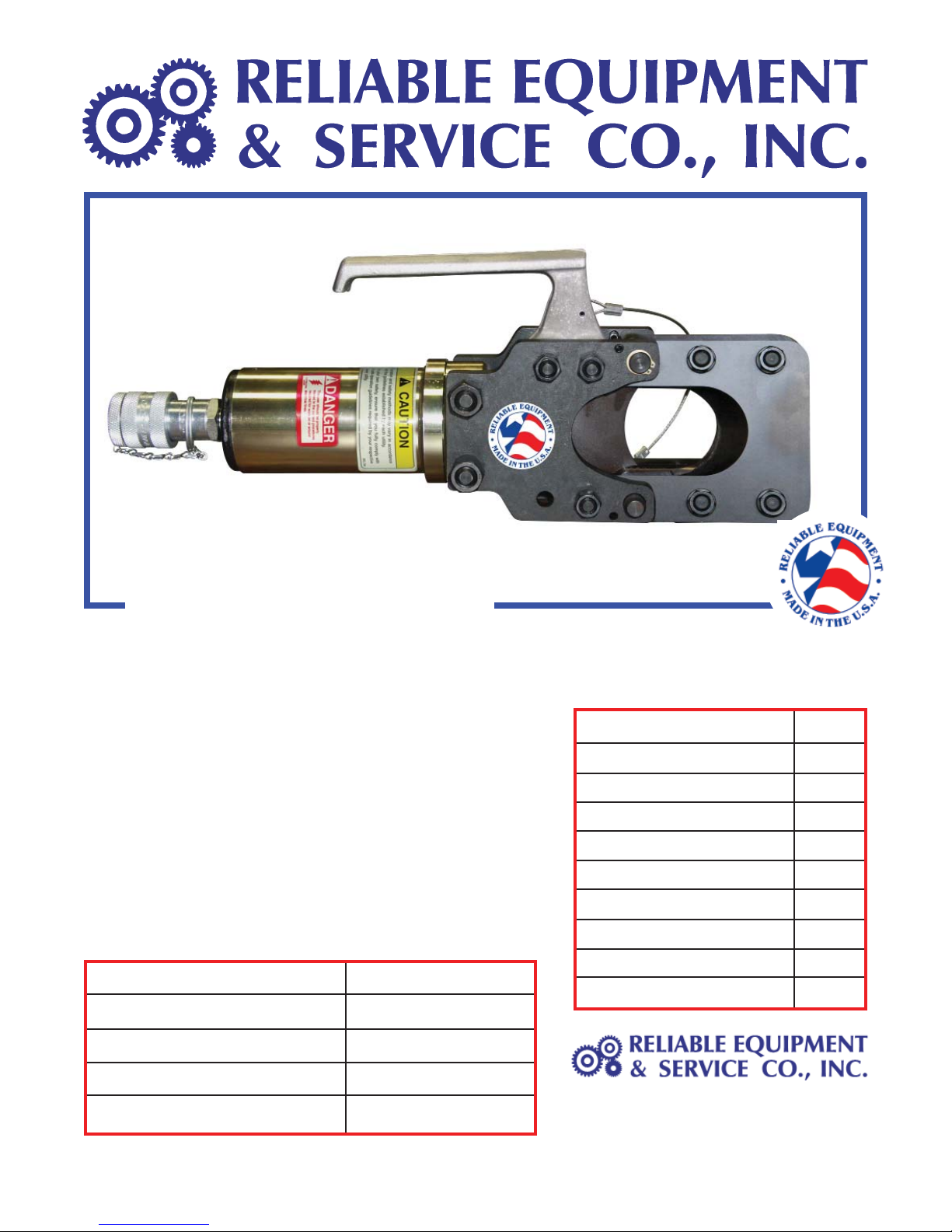
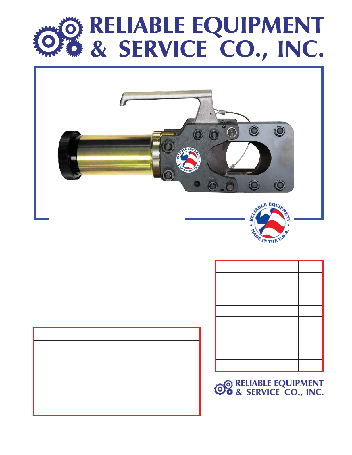
REL-2000 SERIES OPERATION
Read entire manual prior to using this tool.
(Refer to all safety recommendations and warnings)
Observe all safety precautions and procedures required by the operating company.
(Refer to GENERAL SAFETY on page 8)
Before cutting, ensure that material being cut is within the capacity listed for this tool.
Tool must be used in conjunction with a hydraulic system rated at, and adjusted to, 10,000 psi.
Any system not operating at 10,000 psi may cause damage to the tool and result in serious
injury to the operator.
Connect the tool head to the control valve or hose set. (Refer to warnings on page 6 & 7)
Open cutter by removing locking pin.
Insert material between cutter head and blade.
Close and secure cutter head using locking pin.
Important: Failure to secure head may result in severe tool damage and/or personal injury.
The material to be cut MUST be at a 90Oangle to the blade. This will ensure a proper cut
with minimal distortion. Severe blade damage may occur if material is cut at any other angle.
Operate pump or valve to slowly advance blade. If a hold feature is available, check for proper
alignment (90Oangle) of blade and material being cut.
Continue until cut is complete.
SA: Return source to the OFF/RETRACT position and allow movable blade to retract completely.
DA: Use Valve or pump to retract the blade.
Do not cut live conductors.
Hardened metals may fly when severed.
Take necessary precautions. wear safety glasses.
Keep all body parts away from cutting blades and moving parts.
WARNING
Failure to follow these rules can result in serious personal injury or death.
WARNING
CUTTING DANGER
This hydraulic cutting tool can cut, dismember and/or disable.
KEEP ALL PARTS OF THE BODY AWAY FROM MOVING PARTS.
DO NOT lock the tool in the On Position. In an emergency, serious
damage or injury could occur during the time required to stop the tool.
Failure to observe this warning could result in serious injury

11
BEFORE USING THIS PRODUCT
READ THE SAFETY WARNINGS
and recommended practices described
in the manual. Failure by the operator to
read and fully understand the warnings
will leave this person unqualifi ed to use
and operate the tool.
Failure to observe all warnings and instructions could result
in property damage, severe personal injury, and/or death.
REL-SM
WARNING
DANGER
BLADE
CLOSES
NOTE: Keep Label Set clean and legible. Replace decals when necessary.
RELIABLE EQUIPMENT & SERVICE CO., INC.
92 Steamwhistle Drive • Ivyland, PA 18974 • USA
Phone: 215-357-3500 • Fax: 215-357-9193
MODEL: PDC-2000
MAX. PRESSURE: 10,000 PSI
SERIAL NO.: ____________
YEAR: ___________
COMPLETE DISASSEMBLY IS NOT RECOMMENDED
Return the unit to an authorized dealer for total disassembly and/or repair.
All maintenance or disassembly should take place on a flat, clean work surface covered with
towels or wipers so as to have a clean space for the disassembled parts.
Inspect each part during disassembly for wear, scratches, and cuts. Discard the worn or
damaged parts and replace with new factory authorized parts.
O-rings are sensitive to sharp edges. Inspect closely for cuts or damage. A small cut will
cause a leak. When assembling or disassembling O-rings, use hydraulic fluid as a lubricant
to help disassembly or installation.
IMPORTANT: The greatest cause of hydraulic system failure is dirt.
Prevent the introduction of foreign matter into the unit via hydraulic fluid,
dirty connections or accumulation of sediment.
DAILY MAINTENANCE
The life, reliability, and safety of the tool is dependent on proper maintenance.
Clean all surfaces including head, blade, couplers (if coupled), threads, and handles.
Inspect for wear and damage. Worn or damaged parts may malfunction during operation.
All parts must be replaced with new parts if signs of wear or damage are evident.

12
REL-2000SA -CUTTING TOOL
PARTS DRAWING
NOTE: # 21 & 28 have been tightened
to 30-40 Foot Pound of totque, and secured
using Blue LOCTITE on the nuts.

13
ITEM PART NO. QTY DESCRIPTION
1 R23001 1 MOVING BLADE
2 R23040 2 RETAINING PLATE
3 R23003 1 PIVOT PIN
4 R23004A 1 HINGED CUTTER ASSY. (Incl. 21, 28, 29, 30, 31)
5 R23005 3 SMALL STUD
6 R23006 2 LARGE STUD
7 R23007 1 GUIDE ROLL
8 R23008 1 CONNECTING PIN
9 R20510 1 RETURN SPRING ASSY
10 R23010 1 DETENT PIN W/ CABLE
11 R23011 1 BODY
12 R23501 1 S/A PISTON
13 R23502 1 CAP
14 R23014 2 RETAINING RING
15 R23015 1 HANDLE
18 R23018 1 SPRING PIN
19 R23019 2 DOWEL
20 R23020 6 SPLIT LOCK WASHER
21 R23021 10 HEX NUT
22 R23022 4 SPLIT LOCK WASHER
23 R23023 4 HEX NUT
24 R23024 1 * WIPER
25 R23025 3 * BACK UP RING
26 R23026 2 * O-RING
27 R20509 1 SCREW, SPRING ASSY
28 R26024 4 BOLT, HEX 3/8-16X1.67LG
29 R23035 1 CUTTING HEAD (Incl. w/ #4 Cutter Assy.)
30 R23036 2 SPACER, BLADE (Incl. w/ #4 Cutter Assy.)
31 R23037 2 GUIDE, BLADE (Incl. w/ #4 Cutter Assy.)
R23550 1 SEAL KIT * ITEMS IN SEAL KIT
PARTS LIST - REL-2000SA
2” SINGLE ACTING HYDRAULIC CUTTING TOOL
Contact RELIABLE EQUIPMENT at 800-966-3530 if you have any
questions related to the instructional information found in this manual.

14
PDC-2000 -CUTTING TOOL
PARTS DRAWING
NOTE: # 21 & 28 have been tightened
to 30-40 Foot Pounds of torque, and secured
using Blue LOCTITE on the nuts.

15
PDC-2000 PARTS LIST
# PART QTY PART #
1 MOVING BLADE ...............................................................................1 R23001
2 RETAINING PLATE ...........................................................................2 R23002
3 PIVOT PIN ........................................................................................1 R23003
4 HINGED CUTTER ASSY. (Incl. 21, 28, 29, 30, 31) ........................1 R23004A
5 SMALL STUD ....................................................................................3 R23005
6 LARGE STUD ...................................................................................2 R23006
7 GUIDE ROLL ....................................................................................1 R23007
8 CONNECTING PIN ...........................................................................1 R23008
9 INNER PISTON .................................................................................1 R23009
10 DETENT PIN W/ CABLE ...................................................................1 R23010
11 BODY ................................................................................................1 R23011
12 PISTON .............................................................................................1 R23012
13 END BLOCK .....................................................................................1 R23013
14 RETAINING RING .............................................................................1 R23014
15 HANDLE ...........................................................................................1 R23015
16 O-RING .............................................................................................2 *
17 STOP SCREW ..................................................................................1 R15006
18 SPRING PIN .....................................................................................1 R23018
19 HARD DOWEL ..................................................................................2 R23019
20 SPLIT LOCK WASHER .....................................................................6 R23020
21 HEX NUT ..........................................................................................10 R23021
22 SPLIT LOCK WASHER .....................................................................4 R23022
23 HEX NUT ..........................................................................................4 R23023
24 WIPER RING ....................................................................................1 *
25 BACKUP RING .................................................................................3 *
26 O-RING .............................................................................................2 *
27 BACK UP RING ................................................................................1 *
28 O-RING .............................................................................................1 *
29 O-RING .............................................................................................2 *
30 ADJUSTING SCREW .......................................................................2 #
31 SPRING ............................................................................................2 #
32 BALL RETAINER ..............................................................................1 #
33 CHECK BALL ....................................................................................1 #
34 BOLT, HEX 3/8-16X1.67LG ...............................................................4 R26024
35 CUTTING HEAD (Incl. w/ #4 Cutter Assy.) .....................................1 R23035
36 SPACER, BLADE (Incl. w/ #4 Cutter Assy.) ....................................2 R23036
37 GUIDE, BLADE (Incl. w/ #4 Cutter Assy.) .......................................2 R23037
THREAD PROTECTOR ....................................................................1 R1220-19
* SEAL KIT ..........................................................................................1 R23100
# ITEMS ARE INCLUDED AS PART OF THE END CAP ASSEMBLY
PCU-2000 (Also includes couplers below)
HIGH PRESSURE COUPLER - MALE .............................................1 130868
HIGH PRESSURE COUPLER - FEMALE ........................................1 130878

16
301 Ivyland Road • Warminster, PA 18974
Phone: 800-966-3530 • Fax: 215-357-9193
Visit us on the web at www.Reliable-Equip.com
If you have any questions regarding the information
found in this manual please contact RELIABLE EQUIPMENT
at the address, phone or fax numbers shown below.
Date Parts or Service Required
Maintenance Records
This manual suits for next models
2
Table of contents
Other Reliable Equipment Cutter manuals
Popular Cutter manuals by other brands

EASTMAN
EASTMAN BRUTE 627VS INTRUCTION AND PARTS LIST

Kaufmann
Kaufmann SuperLine Series user guide

DeWalt
DeWalt XR DCS438 manual

Professional Picture Frame Equipment
Professional Picture Frame Equipment Onyx 90 owner's manual

Huskie Tools
Huskie Tools REC-634YC Operation manual

Tin Knocker
Tin Knocker TK 816 Instructions & parts diagrams