Reliable Equipment REL-58MC Manual

DISTRIBUTED BY
OPERATORS’ GUIDE
REL-58MC Manual 0
9-17
RELIABLE EQUIPMENT & SERVICE CO., INC.
301 Ivyland Road • Warminster, PA 18974 • USA
Phone: 215-357-3500 • Fax: 215-357-9193
MODEL: _____________________________________
MAX. PRESSURE: ____________________________
SERIAL NO.: _________________________________
YEAR: ______________________________________
NOTICE
Sizes, weights and tool
specifications listed in
this manual are subject
to change without notice.
Please consult factory for
information and updates.
6 TONS OF CUTTING FORCE
REL-58MC
MANUAL HYDRAULIC
CUTTING TOOL
WARNING
All information found in this guide
must be read and understood before
use or testing of this tool.
Failure to read and understand these warnings
and safe handling instructions could result in
severe personal injury and or death.

2

3
REGISTRATION
UPON RECEIPT OF THIS TOOL, COMPLETE THE REGISTRATION BELOW.
COMPANY _____________________________________________________________
ADDRESS _____________________________________________________________
________________________________________________________________________
PHONE _______________________ FAX____________________________________
SERIAL NUMBER _______________________________________________________
DATE OF PURCHASE ___________________________________________________
DEALER NAME _________________________________________________________
CAUTION
The information in this manual is intended to guide the user
in the use and application of this tool. It is not intended as
a substitute for proper training and experience in safe work
practices for this type of equipment.
Consult your supervisor or safety personnel if you have any
questions regarding the safe operation of this tool.
DISTRIBUTED BY

4
TABLE OF CONTENTS
THIS SYMBOL INDICATES ITEMS OF EXTREME IMPORTANCE.
Safety of user and others may be in jeopardy if these instructions
are not read and understood.
DISTRIBUTOR INFORMATION ............................................................. 3
REGISTRATION ..................................................................................... 3
TABLE OF CONTENTS ......................................................................... 4
TOOL SPECIFICATIONS
REL-58MC - MANUAL HYDRAULIC........................................ 5
SAFETY INFORMATION AND WARNINGS........................................ 6-7
OPERATING INSTRUCTIONS ............................................................... 8
MAINTENANCE ..................................................................................... 9
GENERAL MAINTENANCE.................................................................... 9
PARTS DIAGRAM 1 ............................................................................. 10
PARTS DIAGRAM 2 ............................................................................. 11
PARTS DIAGRAM 3 (HEAD ASSEMBLY, EXPLODED VIEW).............. 12
PARTS DIAGRAM 4 (MULTIPLE COMPONENT ASSEMBLIES) ........ 12
PARTS LIST ......................................................................................... 13
MAINTENANCE RECORDS................................................................. 22
CONTACT INFORMATION .................................................................. 13
If you have any questions regarding the information
found in this manual please contact RELIABLE EQUIPMENT
at 800-966-3530 or FAX 215-357-9193.

5
REL-58MC
MANUAL HYDRAULIC CUTTER
Among the smallest hydraulic cutters available.
This powerhouse is designed to cut 1” copper,
aldrey, aluminum, and aluminum-steel cables,
7/8” guy wire and steel ropes, as well as 5/8”
EHS* and ground rod.
The tool features a double speed action.
The blades are manufactured from special high
strength steel, that is heat treated to ensure a
long service life.
The cutter head rotates 180 degrees, to enable
the operator to work in the most comfortable
position, and can easily be opened to allow the
cutting of running cables.
The REL-58MC features an automatic safety
valve to bypass oil when reaching maximum
pressure; a pressure release device can also
be operated at any stage of operation.
301 Ivyland Road • Warminster, PA 18974
Phone: 800-966-3530 • Fax: 215-357-9193
Visit us on the web at www.Reliable-Equip.com
REL-58MC
MANUAL HYDRAULIC
CUTTING TOOL
SPECIFICATIONS
Length 15.75 inches
Weight 7.7 lbs.
Pressure 10,000 psi (manual)
Capacity 1 in. Al., Cu, Steel Rope
7/8” Guy Wire
5/8 in. Ground Rod, EHS*
6 TONS OF CUTTING FORCE
* Capacity may vary with cable stranding and
EHS steel hardness.

6
WARNING
BEFORE USING THIS TOOL, READ THE WARNINGS
and the recommended practices described in this manual.
Failure by the operator to read and fully understand these
warnings will leave this person unqualified to use and
operate this tool. Property damage, severe personal injury,
and/or death could result by not following these warnings.
Eye Protection
Always wear eye
protection to avoid
These warnings will appear in appropriate locations when they are pertinent to the
particular subject being shown. Read each one carefully and follow them strictly.
WARNING
injury from flying debris or hydraulic
oil leaks. Failure to do so can result
in serious personal injury.
Hard Hat
Always wear a hard
WARNING
hat to avoid injury from falling debris.
Failure to do so can result in serious
personal injury.
Hearing
Protection
Always wear hearing
WARNING
protection, to avoid hearing loss due to
long term exposure to high noise levels.
Foot
Protection
WARNING
Always wear foot protection.
Failure to do so can result in serious
personal injury.
Skin
Irritation
WARNING
WARNING
Protective
Gloves
Always wear protective gloves
Failure to do so can result in serious
personal injury.
Hydraulic oil may cause irritation.
Use care to prevent contact with skin.
In case of accidental contact, wash
affected area immediately

7
GENERAL SAFETY
FAILURE TO HEED THESE WARNINGS COULD RESULT IN
PROPERTY DAMAGE, SERIOUS PERSONAL INJURY OR DEATH.
ELECTRICAL SHOCK HAZARD
Always wear and use the necessary clothing, equipment and
safety practices to protect against electrical shock. Failure to
follow these rules can result in serious personal injury or death.
WARNING
WARNING
CUTTING DANGER
This manual hydraulic cutting tool can cut and/or disable.
KEEP ALL PARTS OFCTHE BODY AWAY FROM MOVING PARTS.
Failure to observe this warning could result in serious injury
USE ALL APPROPRIATE AND APPLICABLE PERSONAL SAFETY EQUIPMENT as required
by the operating company.
INSPECT TOOL BEFORE USE. Replace any worn, damaged or missing parts.
A damaged or improperly assembled tool may injure operator and/or nearby personnel.
KEEP ALL PARTS OF THE BODY AWAY from moving parts of the tool.
KEEP HANDS OUT FROM BETWEEN CUTTING BLADES AT TOOL HEAD.
ALL BODY PARTS SHOULD BE OUTSIDE DANGER ZONE PRIOR TO CUTTING.
MAKE SURE there is no person in close proximity to you or the tool who could
be injured by any operation being performed, tool malfunction or flying debris.
DO NOT OVEREXTEND your position by overreaching or unbalancing the footing necessary
to maintain physical control of your body and the tool.
ALWAYS MAINTAIN a firm grip on the tool to avoid loss of control during an operation,
causing property damage, serious injury or death.
USE THIS TOOL FOR THE MANUFACTURERS’ INTENDED PURPOSE ONLY.
OBSERVE CLOSELY ALL OF THE SAFETY RULES FOR A PARTICULAR JOB CLASS
Operation/Safety methods may vary in accordance with the working guidelines established
by each utility or contractor. Ensure that you fully comply with all safe operation guidelines
required by your employer.

8
OPERATION
IF YOU HAVE ANY QUESTIONS REGARDING THE PROPER USE
AND/OR OPERATION OF THIS TOOL, CONSULT YOUR AREA SUPERVISOR,
OR CONTACT RELIABLE EQUIPMENT AT 800-966-3530
Read entire manual prior to using this tool. Refer to all safety cautions and warnings.
Do not cut live conductors.
Hardened metals may fly when severed.
Take necessary precautions. waer safety glasses.
Keep all body parts away from cutting blades and moving parts.
WARNING
6. Pump handle (D) to advance cutting blade up to subject. Check tool alignment.
7. Continue pumping handle until cut is complete.
8. Retract blade completely by pressing hydraulic release lever (A).
1. Before cutting, ensure that subject is within the capacity listed for the tool. (see page 4)
2. Retract blade completely by pressing hydraulic release lever (A).
3. Release latch (B), and open tool head for simple tool positioning around subject to be cut.
NOTE: Tool head rotates 180O to aid in proper alignment.
4. Place subject in tool head (C) and close latch securely.
NOTE: Failure to secure latch may result in severe tool damage and/or personal injury.
5. Position subject at a 90O angle to the tool head and cutting blade.
NOTE: Failure to cut subect at the proper 90O angle may result in severe tool
damage and/or personal injury.
Failure to follow these rules can result in serious personal injury or death.
Observe all safety precautions
and procedures required by
the operating company.
B LATCH
CHEAD
A RELEASE LEVER
STATIONARY HANDLE
PUMP
HANDLE
D

9
Complete disassembly is not recommended. Return the unit to an authorized dealer for
total disassembly and/or repair.
All maintenance or disassembly should take place on a flat, clean work surface
covered with towels or wipers so as to have a clean space for the disassembled parts.
Inspect each part during disassembly for wear, scratches, and cuts. Discard the worn or damaged
parts and replace with new factory authorized parts. See parts drawings on pg16-20.
O-rings are sensitive to sharp edges. Inspect closely for cuts or damage. A small cut will cause
a leak. When assembling or disassembling O-rings, use hydraulic fluid as a lubricant to help
disassembly or installation.
When disposing of hydraulic parts or components observe all federal, state, and local guidelines.
IF YOU HAVE QUESTIONS REGARDING THE REPAIR AND MAINTENANCE
OF THIS TOOL CONTACT RELIABLE EQUIPMENT AT 800-966-3530
GENERAL MAINTENANCE
DAILY MAINTENANCE
The life, reliability, and safety of the tool is dependent on proper maintenance.
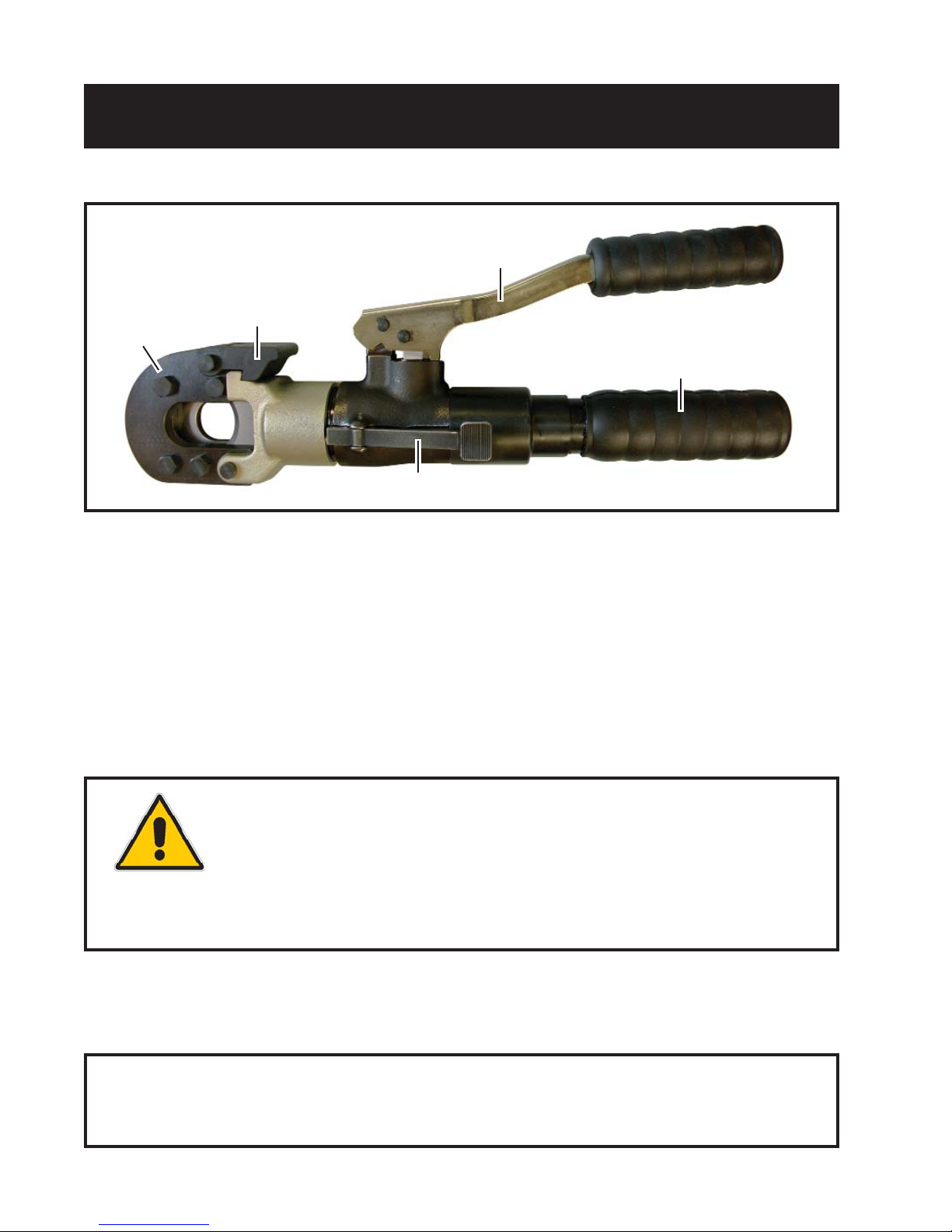
Clean and inspect all surfaces including head, latch mechanism, blade, ram, body and handles.
WARNING blade, head and handles may cut or pinch. Please use extreme caution.
Worn or damaged parts (i.e. chipped or cracked blade) may malfunction during operation,
causing more extensive damge to the tool and/or severe injury to the operator or bystander..
All parts must be replaced with new parts if signs of wear or damage are evident.
Keep Label Set clean and legible. Replace decals when necessary.
BEFORE USING THIS PRODUCT
READ THE SAFETY WARNINGS
and recommended practices described
in the manual. Failure by the operator to
read and fully understand the warnings
will leave this person unqualifi ed to use
and operate the tool.
Failure to observe all warnings and instructions could result
in property damage, severe personal injury, and/or death.
R
WARNING
Hardened metals may fly when severed
Take necessary precautions. Wear
safety glasses do not cut live
conductors. Keep fingers away from
cutting blades and moving parts.
Secure latch before operating tool
Failure to secure latch can result in tool
damage and personal injury.
NOTE:
Warning, Caution, & Danger Labels
are now on a single label # TMP4x1
Hardened Metals Label is # 20-CSL

10
REL-58MC
PARTS DRAWING
DIAGRAM 1
Reference
Dia. 4F
Reference
Dia. 4C
FOR PARTS LIST AND
MULTIPLE COMPONENT
ASSEMBLIES DIAGRAM 4A-F
SEE PAGES 11 &12
66

11
REL-58MC
PARTS DRAWING
DIAGRAM 2
Reference
Dia. 4E
Reference
Dia. 4A Reference
Dia. 4D
Reference
Dia. 4B
66

12
REL-58MC
EXPLODED HEAD
DIAGRAM 3
A B C D E F
REL-58MC
MULTIPLE COMPONENT
ASSEMBLIES DIA. 4
Udate 04/14 begin with SN# 3003
58
33
32
59
40
60
34 50
47
48
66
41
46
57
55
56
33
66
32
41
43
43
14
13 2
62
12
3
4
5
17
16
15
49

13
ITEM PART QTY DESCRIPTION
1 R36001 1 .......................................... BODY
2 R36002 1 .......................................... HEAD SUPPORT
3 R36003 1 .......................................... CUTTER HEAD
4 R36004-1 1 .......................................... SPACER, CUTTER HEAD
5 R36005 1 .......................................... SUPPORT, CUTTER HEAD
6 R36006 1 .......................................... CUTTER BLADE
7 R36007 1 .......................................... SCREW, BLADE HOLDER
8 R36008 1 .......................................... RAM
9 R36009 1 .......................................... SPRING, RAM
10 R36010 1 .......................................... GUIDE RING
11 R36011-1 1 .......................................... LATCH
12 R36012 1 .......................................... SPRING (LATCH)
13 R36013 2 .......................................... PIVOT PIN (HEAD ASSEMBLY)
14 R36014 4 .......................................... BOLT
15 R36015 4 .......................................... NUT
16 R36016 4 .......................................... WASHER
17 R36017 2 .......................................... C-CLIP (HEAD PIVOT PINS)
18 R36018 1 .......................................... INJECTOR
19 R36019 2 .......................................... PIN (MOVEABLE HANDLE)
20 R36020 4 .......................................... C-CLIP (MOVEABLE HANDLE)
21 R36021 1 .......................................... HANDLE, MOVEABLE
22 R36022 1 .......................................... LARGE GRIP
23 R36023 1 .......................................... SMALL GRIP
24 R36024 1 .......................................... OIL RESERVOIR
25 R36025 1 * .......................................... O-RING (RESERVOIR)
26 R18026 1 .......................................... PLUG W/ MAGNET
27 R36027 1 .......................................... HANDLE
30 R36030 1 .......................................... LEVER
31 R36031 1 .......................................... COILED ROLL PIN (FOR LEVER)
32 R36032 2 .......................................... 5/32 HARD BALL
33 R36033 2 .......................................... SPRING (FOR 5/32 HARD BALL)
34 R36034 1 .......................................... POP OFF VALVE
40 R18208 1 * .......................................... O-RING, SEAT (POP-OFF VALVE)
41 R36036 2 .......................................... SPRING (FOR 1/4 DIA. BALL)
42 R36037 1 * .......................................... WIPER (FOR PLUNGER)
43 R36038 2 .......................................... SCREW POSITIONING (FOR 1/4 DIA. BALL)
44 R36039 1 .......................................... PRESSURE RELEASE PIN
45 R18013 1 * .......................................... O-RING (PRESSURE RELEASE PIN)
46 R36041 1 .......................................... 7/32 DIA HARD BALL
47 R36042 1 .......................................... BALL SUPPORT (PRESSURE RELEASE ASSY)
48 R36043 1 .......................................... SPRING (GOES ON BALL SUPPORT)
49 R36044 1 .......................................... BOLT (PRESSURE RELEASE ASSY)
50 R36045 1 * .......................................... O-RING (ASSEMBLE ON PRESSURE RELEASE BOLT)
51 R36046 1 .......................................... PIN LEVER SUPPORT
52 R36047 1 .......................................... SPRING (GOES WITH PIN LEVER SUPPORT)
53 R36049 1 * .......................................... BACK-UP RING
54 R36048 1 * .......................................... O-RING (GOES ON RAM)
55 R36050 1 .......................................... SCREW, FAST ADVANCE
56 R36051 1 .......................................... PINTLE, FAST ADVANCE
57 R36052 1 .......................................... SPRING, FAST ADVANCE
58 R36053 1 * .......................................... COPPER WASHER
59 R36054 1 .......................................... INLET CHECK VALVE
60 R36055 1 .......................................... VENT
62 R36057 1 .......................................... SLIDE PIN (FOR LATCH)
63 R36058 1 .......................................... SET SCREW
64 R36059 1 * .......................................... O-RING, SMALL (FOR PLUNGER)
65 R36060 1 * .......................................... O-RING, LARGE (FOR PLUNGER)
66 13167 2 .......................................... 7/32 DIA HARD BALL (Udated 9/17 begin SN# 3971)
R36100 .......................................... PRESSURE TEST PLUG
R36200 .......................................... SEAL KIT (* ITEMS)

14
Date Parts or Service Required
MAINTENANCE RECORDS
301 Ivyland Road, Warminster, PA 18974
Phone: 800-966-3530 Fax: 215-357-9193
Visit us on the web at www.Reliable-Equip.com
If you have any questions regarding the information
found in this manual please contact RELIABLE EQUIPMENT at the address,
phone or fax numbers shown below.
Table of contents
Other Reliable Equipment Cutter manuals
Popular Cutter manuals by other brands

Cembre
Cembre TC 120 Operation and maintenance manual

Vivo
Vivo CUTR-F003 instruction manual

Tar River
Tar River ERC Series Operator's manual

XPOtool
XPOtool 62059 operating instructions

Logan Graphic Products
Logan Graphic Products 545 instruction manual

Craftwell
Craftwell Teresa Collins Cut'N'Boss user manual