Reliance Radiance RAPID RTIU702 Series User manual

Installation and Maintenance Instructions
Radiance®Thermal Interface Units (TIU)
RAPID - RTIU702XXX
Twin plate exchanger unit to generate instantaneous DHW
with indirect heating connections.
Designed and
manufactured
in the UK
Conforms to Building Regulations Part L (2010)

Contents
Reliance Worldwide Corporation (UK) Ltd 3
Dos and Don’ts 4
Safety 5
Abbreviations 6
General Information 6
Working Parameters and Specifications 7
Dimensions 8
Internal System Components
Schematic 9
Diagram 10
Operation 11
Domestic Hot Water Demand 11
Space Heating Demand 11
Installation 12
Unpacking the unit 12
Installation - No First Fix Rail and No Stand
Off Frame
13
Fitting Location 13
Fitting Template 13
Wall Mounting 13
Connecting the Ball Valves 13
Fitting Template (Example) 14
Installation - with First Fix Rail and no Stand
Off Frame
15
Mechanical Fixing 15
Installing the First Fix Rail 16
Fitting Template 17
Wall Mounting 17
Connecting the Ball Valves 17
Installation - Stand Off Frame with (Optional)
First Fix Rail
18
Mechanical Fixing 18
Installing the First Fix Rail for Stand
Off
19
Stand Off Frame Assembly 19
Fixing the Stand Off Frame to the
FFR for Stand Off Frame
20
Fixing the Stand Off Frame Directly
onto the wall
20
Mounting the TIU to the Stand Off
Frame
20
Connecting the Ball Valves 21
Replacing the Cover 22
Hydraulic Connections 23
SharkBite®Metal Push-Fit Connectors 24
Electrical Installation 25
Junction Box 26
Circuit Diagram 26
Commissioning 27
Flushing the Network 27
Filling the TIU 27
Filling the Primary Circuit 27
FIlling the Mains Water Circuit 27
FIlling the Secondry Circuit 27
Differential Pressure Control Valve 28
Diverter Valve 29
Disassembly 29
Assembly 30
Thermostatic By-pass Valve &
Thermostatic Heating Control Valve
31
Zone Valve 31
Thermostatic Mixing Valve 32
Servicing the TMV 32
Pump 33
Heat Meter 33
Error Codes 33
Screen Functions 34
Maintenance 35
Strainers 35
Troubleshooting 36
Fault Finding Flowchart 37
Symptoms and Actions 38
Spares and Accessories 39
Commissioning Check Sheet 40
Servicing and Service Records 41

Reliance Worldwide Corporation (UK) Ltd
Reliance Worldwide Corporation (UK) Ltd®is part of the Australian based group of companies
collectively known as Reliance Worldwide Corporation with two brands represented in the UK:
Reliance Water Controls®and SharkBite®.
Reliance Worldwide Corporation have offices and manufacturing plants throughout the world
providing a wealth of knowledge and expertise which is delivered throughout our entire product
range. Reliance Worldwide Corporation (UK) Ltd have a long history in supplying the sanitary
plumbing market and hot water system manufacturers and are at the forefront of developing
thermostatic technology in the UK. As specialists in the design, manufacturing and technical
support for pressure, temperature and flow control, we also played a key role in the development
of unvented hot water systems in the UK. Our Reliance Water Controls range offers a
comprehensive selection of thermostatic mixing valves, taps, showers, pressure reducing valves,
backflow prevention products, timeflow controls and other plumbing and heating system products.
Our reputation is built upon over of 30 years experience both as a direct supplier and as an OEM
manufacturer to many of the UK plumbing and heating industry’s leading brands for safety valves
in G3 unvented systems and Underfloor Heating (UFH) Controls.
We are certified manufacturers to BS EN 9001 and 14001 and also have an in house UKAS
accredited test laboratory.
We are also members of multiple industry and trade associations, which allows us to remain at
the forefront of new regulations and changes within the industry, which we reflect in our ongoing
product development and innovations.
3

Dos and Don’ts
Do Not:
• Over tighten the union connections as this can split the bre washer.
• Remove the clips at the top of the unit holding the rail connectors in place.
• Get any solder, ux or dirt inside the unit or into the ball valves or connections.
• Flush and/or pressure test the network while the unit is connected to it.
• Flush the primary or secondary side through the unit.
• Use ux or chemicals which could harm parts made of stainless steel, brass, copper or
bre washers
Do:
• Always use two tools to block the adjacent part when tightening a union nut connection
so that other connections are not affected and accidentally loosened.
•
Ensure all connections are leak free after installation
4

Safety
Please read this instruction and maintenance guide carefully before begining the
installation. Reliance Worldwide Corporation (UK) Ltd (RWC UK) accepts no liability for
any damage or injury caused by not observing the instructions in this guide. Failure to
comply with these instructions will result in the warranty becoming null and void. Keep
this manual in a safe place for future reference.
If you are in any doubt, please contact the RWC UK technical department on 01386 712400
backplate of the TIU.
The Radiance®TIU comes with a standard warranty of 2 years for material and manufacturing
defects from date of delivery.
Hot Water
Temperatures in the Radiance TIU can reach up to 95°C and can cause severe burns.
Hot Surfaces
The Radiance TIU can get very hot when operating. Take care when working around the
Radiance TIU. Whilst it is operating please avoid touching the pipework and all metal parts,
which could be hot and could result in burns.
Electricity
Before conducting work on the Radiance TIU make sure that it is electrically isolated, either by
unplugging it from the mains supply or turning off the isolation switch. Failure to do so could
result in electric shock. Electrical installation and servicing must be carried out by a qualified
electrician and to the current applicable standards.
Lifting a Radiance TIU
The Radiance TIU weighs up to 45 Kg, always use 2 people to lift the unit. Before lifting make
sure that any obstructions are removed. When lifting ensure a stable position is adopted to
maintain balance and grip. At the start of the lift, slight bending of the back, hips and knees is
preferable to fully flexing the back (stooping) or fully flexing the hips and knees (squatting).
Servicing
The Radiance TIU should be serviced at least annualy by a qualified technician. The servicing
record sheet and the recommended maintenance for the Radiance TIU can be on page 41 of this
Installation & Maintenance (I&M) guide.
Potable Water
All the TIU compounds, joints and seals that are in contact with potable water are WRAS
approved.
Disposal
Please recycle the cardboard packaging. The Radiance TIU itself cannot be disposed of with
household waste. The Radiance TIU needs to be disassembled and the individual components
disposed of according to local regulations.
5

Abbreviations
Below are a list of abbreviations that are used in this booklet:
BCW Boosted Cold Water PHE Plate Heat Exchanger
DHW Domestic Hot Water TBPV Thermostatic Bypass Valve
DPCV Differential Pressure Control Valve THCV Thermostatic Heating Control Valve
FBP Flushing Bypass TIU Thermal Interface Unit
FFR First Fix Rail TRV Thermostatic Radiator Valve
MCB Miniature Circuit Breaker UFH Under Floor Heating
General Information
Radiance®Thermal Interface Units are part of a heating network which is supplied from a central
boiler room. They are designed to provide space heating and domestic hot water to an residence.
The TIU is generally located within the apartment and connects to a heat network and boosted
cold water on the primary (supply) side and to the space heating and DHW outlets on the
secondary side.
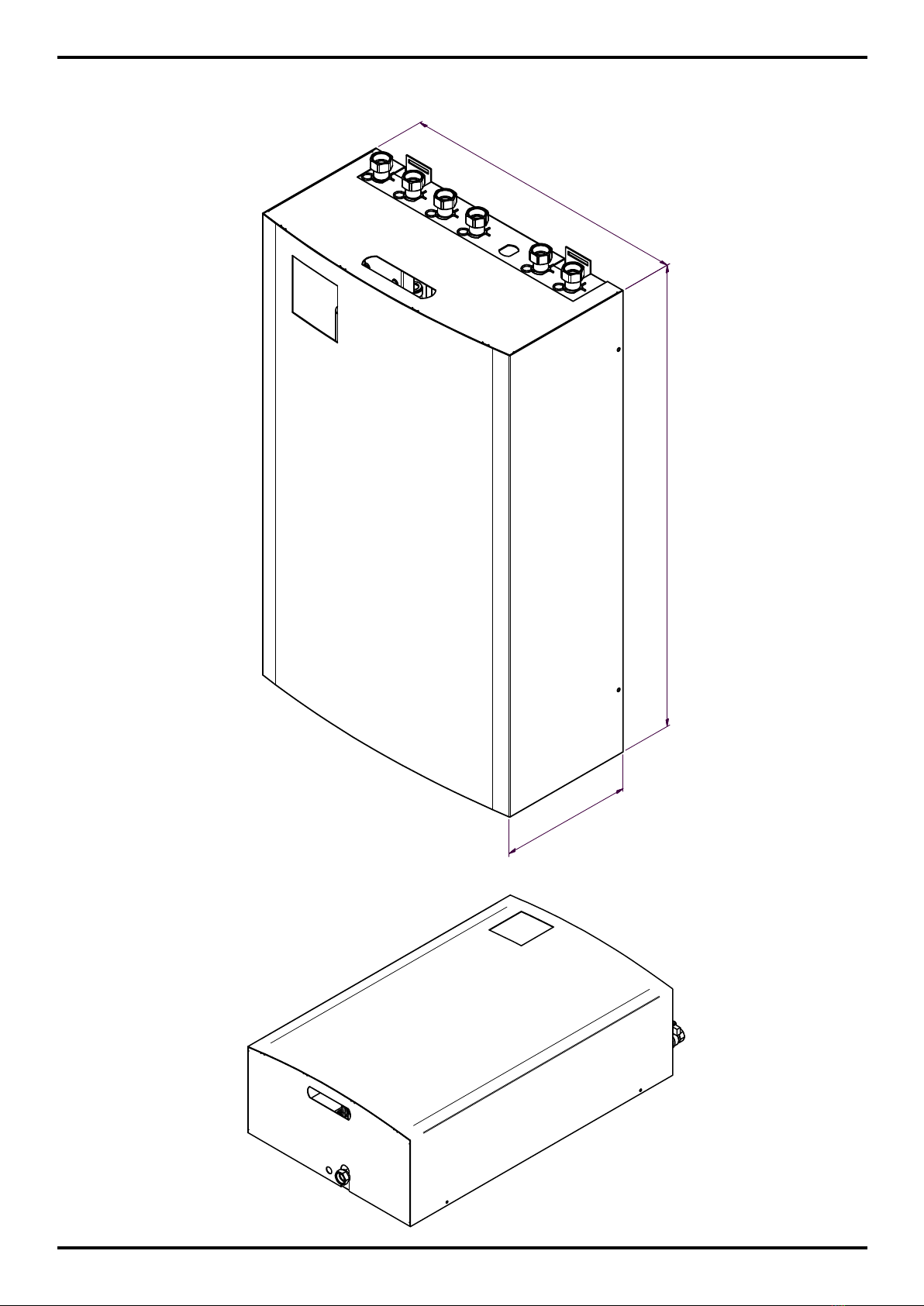
Product Description - Rapid (RTIU702XXX)
The Rapid family of Radiance TIUs are designed to supply indirect heating (hydraulically
separated between the primary and secondary circuit by a plate heat exchanger) and
instantaneous DHW. The hot water is heated at the time of use in a plate heat exchanger and not
stored in a cylinder.
Intended Usage
Radiance TIUs must be installed by a competent person to ensure they perform as designed.
All pipe connections and electrical connections must to be completed by trained professionals
according to and conform to IEE regulations.
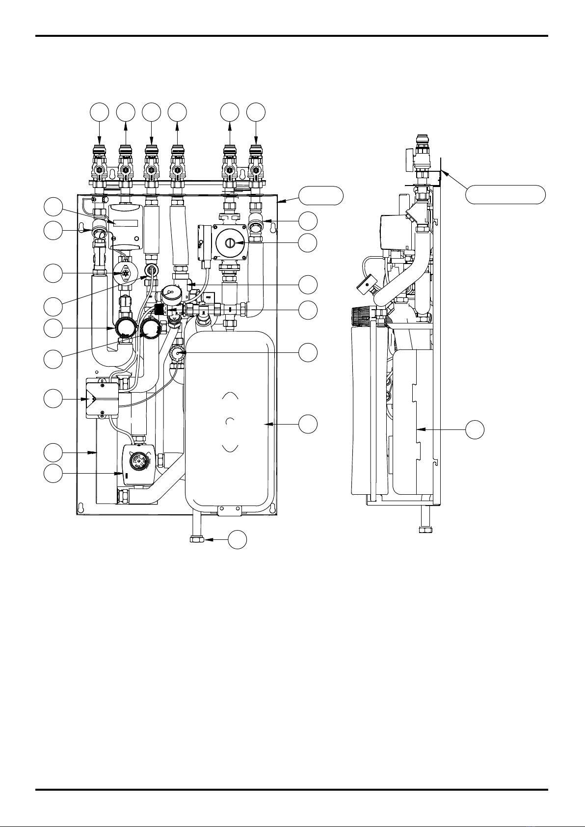
Technical Description
The Rapid family of TIUs are twin-plate (2 PHE) units designed to provide space heating and
DHW. The unit connects the primary heat network, the secondary space heating (radiators or
UFH) and to the BCW supply to produce DHW.
Heating Controls
There is no hydraulic by-pass included on the secondary side of the Rapid TIU. This means that
the external controls need to switch off the “call for heat” when all valves of the heating system
are closed and there is no demand. This will prevent the circulation pump running against a
closed system and consequently overheating.
This issue is normally overcome by fitting the heating controls in the coldest room (for example
the hall) where the radiator should not fitted with a TRV and all valves at the radiator are
fully open. The room thermostat should not be installed in direct sunlight. The hall will now
be temperature controlled by the room stat/timer and the radiator in the hall also performs a
hydraulic bypass to the unit. All other radiators in the system should be fitted with TRVs.
6

Working Parameters and Specications
Rapid Specication:
Indirect heating and instantaneous domestic hot water unit.
Weight 45 (approx.) Kg
Pressure Rating Primary (max.)
Secondary (max.)
Cold water mains (min.)
Cold water mains (max.)
10
3
2
4
bar
bar
bar
bar
Temperature Primary (min.)
Primary (max.)
Domestic hot water
65
95
30-60
°C
°C
°C
Differential Pressure Primary (max.)
Primary (min.)
2.5
0.5
bar
bar
Differential Pressure
Control Valve
Factory set 0.3 bar
Heat Transfer Capacity
*Higher kW available
Heating circuit
DHW circuit
15
42 (Std.)*
kW
kW
DHW Flow Rate Temp. rise from 10°- 50° 15 l/min.
Circulation Pump Branded A rated UK
Standard body 130mm(L)
with 1½" connections
Pump head 6m
External Connections Primary ow
Primary return
Secondary ow
Secondary return
Boosted cold water
Domestic hot water
22mm
SharkBite®
push-t connections
22mm
SharkBite
push-t connections
22mm
SharkBite
push-t connections
22mm
SharkBite
push-t connections
22mm
SharkBite
push-t connections
22mm
SharkBite
push-t connections
or
or
or
or
or
or
¾” FBSP
¾” FBSP
¾” FBSP
¾” FBSP
¾” FBSP
¾” FBSP
Thermostatic Bypass Adjustable 40-70 °C
7

Dimensions
5
0
4
813
2
5
0
All dimensions in mm unless otherwise stated
8

Rapid Internal System Components (Schematic)
Key
1. Ball valve connections
1A - Primary flow (PF)
1B - Primary return (PR)
1C - Secondary flow (SF)
1D - Secondary return (SR)
1E - Domestic hot water (DHW)
1F - Boosted cold water (BCW)
2. Strainers
3. Diverter valve for DHW
4. Plate heat exchanger - heating
5. Circulation pump heating system
6. Heat meter (optional)
7. Differential pressure control valve
8. Thermostatic by-pass valve (optional)
9. Primary zone valve
10.Patented spring loaded, maintenance free expansion vessel
11. Overpressure relief valve with pressure gauge
12.Plate heat exchanger - DHW
13.Thermostatic mixing valve DHW (optional)
14.Flow sensor DHW
15.Thermostatic heating control valve (optional)
9

Rapid Internal System Components (Diagram)
Key
Ball valve connections
1A - Primary flow (PF)
1B - Primary return (PR)
1C - Secondary flow (SF)
1D - Secondary return (SR)
1E - Domestic hot water (DHW)
1F - Boosted cold water (BCW)
Bottom connections
1G - Overpressure relief connection
2. Strainers
3. Diverter valve for DHW
4. Plate heat exchanger - heating
5. Circulation pump heating system
1A 1B 1 C1 D1E 1F
2
6
7
8
12
3
10
2
14
15 9
13
11
4
Backplate First Fix Rail (FFR)
5
G1
16
6. Heat meter (optional)
7. Differential pressure control valve
8. Thermostatic by-pass valve (optional)
9. Primary zone valve
10.Patented spring loaded, maintenance free
expansion vessel
11. Overpressure relief valve with pressure
gauge
12.Plate heat exchanger - DHW
13.Thermostatic mixing valve DHW (optional)
14.Flow sensor DHW
15.Thermostatic heating control valve (optional)
16. Wiring center
10

Operation
The Rapid TIU can either supply heating or domestic hot water but not both simultaneously. The
DHW has an inbuilt priority, the heating will be switched off when DHW is drawn, but as DHW
demands are very short, no impact on the heating performance will be experienced.
DHW Demand
When a hot tap is opened potable cold
water will flow into the unit at (1F) and
through the flow switch (14). The flow
switch activates the diverter valve (3)
which will divert the primary flow into
the PHE for the DHW (12). The potable
cold water will be heated in the PHE
and exitthe PHE as DHW. The optional
TMV (13) will blend the DHW to a pre-set
temperature.
Space Heating Demand
The space heating is controlled by external controls
(timer, programmable room thermostat). When a demand
for heat is generated, the “call for heat” wired into the
TIU will activate the primary zone valve (9). This allows
the primary hot water to flow through the heat exchanger
and simultaneously, start the circulation pump (5) which
will pump the secondary circuit through the radiators.
The secondary water will be heated in the PHE by the
primary hot water flow. The flow rate on the primary side
is controlled by the DPCV (7), the primary zone valve (9)
and if specified the optional thermostatic heating control
valve.
Please see the ‘Electrical Connections’ chapter for the
wiring diagram.
TMV (13)
Plate Heat Exchanger (12)
Diverter Valve (3)
Flow Switch (14)
1F
Circulation Pump (5)
Zone Valve (9)
DPCV (7)
THCV(15)
11

Unpacking
Place the box on a strong, level
surface and open the top cover with
a box cutter.
On top of the TIU is a cardboard
template to protect the cover of the
unit, which is also a fitting template.
Remove the fitting template from the box and keep it safe for the
installation, as it contains all relevant information to mount the unit
to the wall.
Remove the white steel cover of the TIU by lifting it out of the box.
The cover has hand slots in the centre of both ends where it can
be lifted (fig. 1).
When lifting the TIU out of the box make sure that you lift from the
corners, holding the backplate or the expansion vessel. Place the
TIU on a strong, level surface.
Do not lift the TIU with the pipework or connected valves,
as shown below, as this can loosen or damage the pipework
and connections.
PRIMARY
FLOW
PRIMARY
RETURN
COLDWATER
MAINS
DOMESTICHOT
WATER
COLDWATER
OUT
SECONDARY
FLOW
SECONDARY
RETURN
65mm
(CENTRETOCENTRE)
TOPOF
BACK
PLATE
FIXINGPOINT
FIXINGPOINT FIXINGPOINT
FIXINGPOINT
TOPOF
BACK
PLATE
T
hermal Interface Unit
(TIU)
700mm
700mm
479mm
479mm
65mm
(CENTRETOCENTRE)
65mm
(CENTRETOCENTRE)
65mm
(CENTRETOCENTRE)
65mm
(CENTRETOCENTRE)
65mm
(CENTRETOCENTRE)
1) Remove this fitting template from the box and keep it
for the installation.
2) Remove the white steel cover of the TIU by holding the
cover by the openingsin the centre of either end.
3) Lift the TIU out of the box. When lifting the TIU make
sure that you hold it fromthe corners, holding the
backplate or the expansionvessel.
Do not hold the TIU fromthe pipework or components as
this can loosen or damagethe pipework and connections.
1) Select a suitable location which will securely support
the weight of the unit(45kg).
2) The fitting template can simply be hung on the
First Fix Rail (FFR)if this option has been fitted.
3) Otherwise, the fitting template needs to be temporarily
held vertically tothe wall.
4) Drill through the 4 holes which are marked
“Fixing Points” oruse the dimensions printed on the
template.
5) Remove the template and fit suitable wall fixings
before securing theTIU to the wall.
6) The pipe connections at the top are marked with their
location, flow directionsand type of connection.
A
12
Installation
Radiance®TIUs weigh up to 45kg. Always use 2 people to lift the unit. The boxes are clearly
marked with arrows indicating the top of the box. They also have 2 hand slots at both ends to aid
handling.
Fig. 1
Hand slot

TIU Installation - No First Fix Rail and No Stand Off Frame
Fitting Location
Select a location (usually the utility cupboard) where the unit can be
fitted securely to the wall. The unit is heavy and needs a sturdy wall
and appropriate fixings to support its weight. All pipe connections, with
exception of the over pressure relief pipe, are connected at the top. All
top connections at the top are terminated in 22mm SharkBite metal push
fit ball valves or ¾” FBSP connections.
Fitting Template
Hold the cardboard fitting template level at the intended location of the
TIU (fig. 1).
The fitting template should be used to mark where the pilot holes are to
be drilled through the 4 points marked “Fixing Point” (fig. 2). The wall is
now ready to have the TIU mounted to it.
If the fitting template is not available use the dimensions given on page
14 to mark the location of the fixing points
Wall Mounting
1. Insert rawl plugs into the drilled holes.
2. Partially insert the 4 screws with metal washers into the rawl plugs.
3. Hook the TIU over the 4 screws (fig. 3) and slide down so that the
screw head is at the top of the slot (fig. 4).
Note:
Radiance®TIUs
are heavy and weigh up to 45kg. Always use 2 people to lift the units.
4. Tighten the screws with a screwdriver.
The TIU is now wall mounted and ready to have the ball valves connected.
g. 4
g. 3
g. 1
PRIMARY
FLOW
PRIMARY
RETURN
COLD WA
TER
MAINS
DOMESTIC HOT
WATER
COLD WATER
OUT
SECONDARY
FLOW
SECONDARY
RETURN
65mm
(CENTRE TO CENTRE)
TOP OF
BACK
PLATE
FIXING POINT
FIXING POINT FIXING POINT
FIXING POINT
TOP OF
BACK
PLATE
www.rwc.co.uk/radiance
For technical support call 01386 712400
Reliance Worldwide Corporation (UK) Ltd, Worcester Road, Evesham, WR11 4RA
Ther
mal Interface Unit (TIU)
700mm
700mm
479mm
479mm
65mm
(CENTRE TO CENTRE)
65mm
(CENTRE TO CENTRE) 65mm
(CENTRE TO CENTRE)
65mm
(CENTRE TO CENTRE) 65mm
(CENTRE TO CENTRE)
1) Remove this fitting template from the box and keep it
for the installation.
2) Remove the white steel cover of the TIU by holding the
cover by the openings in the centre of either end.
3) Lift the TIU out of the box. When lifting the TIU make
sure that you hold it from the corners, holding the
backplate or the expansion vessel.
Do not hold the TIU from the pipework or components as
this can loosen or damage the pipework and connections.
1) Select a suitable location which will securely support
the weight of the unit (45kg).
2) The fitting template can simply be hung on the
First Fix Rail (FFR) if this option has been fitted.
3) Otherwise, the fitting template needs to be temporarily
held vertically to the wall.
4) Drill through the 4 holes which are marked
“Fixing Points” or use the dimensions printed on the
template.
5) Remove the template and fit suitable wall fixings
before securing the TIU to the wall.
6) The pipe connections at the top are marked with their
location, flow directions and type of connection.
Unpacking the TIU
Fitting the TIU
g. 2
13
Connecting the Ball Valves to the TIU
The ball valves are supplied loose in a separate box and will have
either SharkBite®or ¾”FBSP connections. They connect to the TIU via
a flat face fibre washer sealed union nut connection. To connect the ball
valves to the TIU:
1. Remove the plastic cap from the ball valves, taking care as the cap
contains a loose bre washer inside.
2. Place a bre washer in each ¾” FBSP connection.
3. Screw the nuts at the top of the TIU onto the ball valves, using the
washer to form a seal. Tighten with a spanner.
4. Do not remove the rail clips. These keep the rail connectors in place
and prevents the loosening of internal components.
The TIU is now ready for the pipework connections.
Rail clip

14
PRIMARY
FLOW
PRIMARY
RETURN
COLD WATER
MAINS
DOMESTIC HOT
WATER
COLD WATER
OUT
SECONDARY
FLOW
SECONDARY
RETURN
65mm
(CENTRE TO CENTRE)
TOP OF
BACK
PLATE
FIXING POINT
FIXING POINT FIXING POINT
FIXING POINT
TOP OF
BACK
PLATE
www.rwc.co.uk/radiance
For technical support call 01386 712400
Reliance Worldwide Corporation (UK) Ltd, Worcester Road, Evesham, WR11 4RA
Thermal Interface Unit (TIU)
700mm
700mm
479mm
479mm
65mm
(CENTRE TO CENTRE)
65mm
(CENTRE TO CENTRE) 65mm
(CENTRE TO CENTRE)
65mm
(CENTRE TO CENTRE) 65mm
(CENTRE TO CENTRE)
1) Remove this fitting template from the box and keep it
for the installation.
2) Remove the white steel cover of the TIU by holding the
cover by the openings in the centre of either end.
3) Lift the TIU out of the box. When lifting the TIU make
sure that you hold it from the corners, holding the
backplate or the expansion vessel.
Do not hold the TIU from the pipework or components as
this can loosen or damage the pipework and connections.
1) Select a suitable location which will securely support
the weight of the unit (45kg).
2) The fitting template can simply be hung on the
First Fix Rail (FFR) if this option has been fitted.
3) Otherwise, the fitting template needs to be temporarily
held vertically to the wall.
4) Drill through the 4 holes which are marked
“Fixing Points” or use the dimensions printed on the
template.
5) Remove the template and fit suitable wall fixings
before securing the TIU to the wall.
6) The pipe connections at the top are marked with their
location, flow directions and type of connection.
Unpacking the TIU
Fitting the TIU
This drawing is representative of the tting template and is not to scale

TIU Installation - with First Fix Rail and no Stand Off Frame
The FFR is intended to be used as a first fix support. It is supplied with six SharkBite®22mm
metal push fit connection ball valves as standard or ¾” FBSP connections are also available, as
an alternative. This FFR permits the pipework to be pre-installed independent of the main TIU.
The pipework can be flushed and pressure tested, before the TIU is installed and connected to
the system.
It is critical that the FFR is installed prior to the TIU.
Mechanical Fixing
The drawing below shows the back plate of a TIU mounted onto the optional FFR at the top. The
FFR has 2 fixing points with a dimension of 326mm across centres. The back plate has 4 fixing
points with a dimension of 479mm across the centre.
Heavy duty screws and rawl plugs should be used, which are suitable for the wall type. The TIU
is heavy and weighs up to 45 Kg. If unsuitable screws are used damage could be done to both
the wall and the TIU.
All fixing points are large enough to be used with screws up to 8mm in diameter.
15
Diagram shows backplate and
rst x rail only for ease of
understanding
All dimensions in mm unless
otherwise stated
MADE BYAMDT DETAILS DATE CHECKED DATE CHECKED
ZTIU600004
and
ZTIU600005
ZTIU600004 and ZTIU600005
L Perry
THIS DRAWING AND THE INFORMATION CONTAINED HEREIN IS THE SOLE PROPERTY OF RELIANCE WORLDWIDE, A DIVISION OF GSA INDUSTRIES (AUST.) PTY.LTD. ABN. 71 004 784 301, IS STRICTLY CONFIDENTIAL AND MAY NOT BE USED, COPIED IN WHOLE OR IN PART OR DISCLOSED WITHOUT THE PRIOR SPECIFIC WRITTEN PERMISSION OF RELIANCE WORLDWIDE
19/02/2015
©
-
µm Ra
Reliance
WORLDW IDE
700
479
326
137
77

65mm
(CENTRE TO CENTRE) 65mm
(CENTRE TO CENTRE)
65mm
(CENTRE TO CENTRE)
65mm
(CENTRE TO CENTRE)
65mm
(CENTRE TO CENTRE) 65mm
(CENTRE TO CENTRE)
PRIMARY
FLOW
PRIMARY
RETURN
COLD WATER
MAINS
DOMESTIC HOT
WATER
COLD WATER
OUT
SECONDARY
FLOW
SECONDARY
RETURN
TOP
www.rwc.co.uk/radiance
For technical support call 01386 712400
Reliance Worldwide Corporation (UK) Ltd,Worcester Road, Evesham, Worcestershire,WR11 4RA, UK.
326mm
16
Installing the FFR
Choose a suitable location (usually the utility cupboard) ensuring there is sufficient space to fix
the TIU below where the TIU can be fitted securely to the wall. The TIU is heavy and needs a
sturdy wall and appropriate fixings to support the weight. All pipe connections, apart from the
overpressure relief pipe, are connected at the top.
The box that the FFR is supplied in contains a template which assists the installation. To use the
template:
1. Hold the cardboard fitting template level at the intended location of the TIU.
2. The fitting template can be used to drill pilot holes directly through the red crosshairs or used
to mark the required location of the holes.
3. Insert rawl plugs into the drilled holes.
4. Partially insert the 2 screws with metal washers into the rawl
plugs and hook the FFR over them.
5. Tighten the screws with a screwdriver.

17
TIU Fitting Template
The TIU fitting template is shown on page 14
(not to scale) and is supplied with the TIU. The
cardboard template should be hung directly
onto the FFR. The two rectangular openings at
the top of the template allow the template to be
hung from the FFR (fig. 1).
Once hung, the fitting template can be used
to drill pilot holes directly through the 4 points
marked “Fixing Point”. Remove the fitting
template. The wall is now ready to have the TIU
mounted to it.
PRIMARY
FLOW
PRIMARY
RETURN
COLDWATER
MAINS
DOMESTIC HOT
WATER
COLDWATER
OUT
SECONDARY
FLOW
SECONDARY
RETURN
65mm
(CENTRETOCENTRE)
TOP OF
BACK
PLATE
FIXING POINT
FIXING POINT FIXING POINT
FIXING POINT
TOP OF
BACK
PLATE
www.rwc.co.uk/radiance
For technical support call 01386 712400
Reliance Worldwide Corporation (UK) Ltd, Worcester Road, Evesham, WR11 4RA
Thermal Interface Unit (TIU)
700mm
700mm
479mm
479mm
65mm
(CENTRETOCENTRE)
65mm
(CENTRETOCENTRE) 65mm
(CENTRETOCENTRE)
65mm
(CENTRETOCENTRE) 65mm
(CENTRETOCENTRE)
1) Remove this fitting template from the box and keep it
for the installation.
2) Remove the white steel cover of the TIU by holding the
cover by the openings in the centre of either end.
3) Lift the TIU out of the box. When lifting the TIU make
sure that you hold it from the corners, holding the
backplate or the expansion vessel.
Do not hold the TIU from the pipework or components as
this can loosen or damage the pipework and connections.
1) Select a suitable location which will securely support
the weight of the unit (45kg).
2) The fitting template can simply be hung on the
First Fix Rail (FFR) if this option has been fitted.
3) Otherwise, the fitting template needs to be temporarily
held vertically to the wall.
4) Drill through the 4 holes which are marked
“Fixing Points” or use the dimensions printed on the
template.
5) Remove the template and fit suitable wall fixings
before securing the TIU to the wall.
6) The pipe connections at the top are marked with their
location, flow directions and type of connection.
Unpacking the TIU
Fitting the TIU 65mm
(CENTRE TO CENTRE)
TOP OF
BACK
PLATE
PRIMARY
FLOW
PRIMARY
RETURN
g. 1
g. 2 g. 3
Wall Mounting
1. Insert rawl plugs into the drilled holes.
2. Partially insert the 4 screws with washers into the rawl plugs.
3. Hook the TIU over the 4 screws (fig. 2) and slide down so that the
screw head is at the top of the slot (fig. 3).
Note:
Radiance®TIUs are
heavy and weigh up to 45kg. Always use 2 people to lift the units.
4. Tighten the screws with a screwdriver.
The TIU is now wall mounted and ready to have the ball valves connected.
Connecting the Ball Valves to the TIU
The ball valves are supplied loose in a separate box and will have
either SharkBite®or ¾”FBSP connections. They connect to the TIU via
a flat face fibre washer sealed union nut connection. To connect the ball
valves to the TIU:
1. Remove the plastic cap from the ball valves, taking care as the cap
contains a loose bre washer inside.
2. Place a bre washer in each ¾” FBSP connection.
3. Screw the nuts at the top of the TIU onto the ball valves, using the
washer to form a seal. Tighten with a spanner.
4. Do not remove the rail clips. These keep the rail connectors in
place and prevents the loosening of internal components.
The TIU is now ready for the pipework connections.
Rail clip

TIU Installation - Stand Off Frame with First Fix Rail
The stand off frame enables the pipework to be routed from below the TIU and run behind the
TIU by locating the TIU away from the wall by 40mm. If the stand off frame is to be used in
conjunction with a FFR it must be used with the FFR for stand off frame only. It will not work
with the normal FFR and the pipework will not align.
The FFR for the stand off frame must be wall mounted rst, as the stand off frame hooks onto,
it to provide location.
Mechanical Fixing
The drawing below shows the back plate of a TIU, mounted to the stand off frame, and with the
optional FFR. The FFR has 2 fixing points with a dimension of 454mm across the centre. The
back plate has 4 fixing points with a dimension of 479mm and 700mm across the centres.
Heavy duty screws and rawl plugs should be used, which are suitable for the wall type. The TIU
is heavy and weighs up to 45 Kg. If unsuitable screws are used damage could be done to both
the wall and the TIU.
All fixing points are large enough to be used with screws up to 8mm in diameter.
18
454
12
141
700
479
Diagram shows backplate and
rst x rail only for ease of
understanding
All dimensions in mm unless
otherwise stated

19
Installing the FFR
Choose a suitable location (usually the utility cupboard) ensuring there is sufficient space to fit
the TIU below where the TIU can be fitted securely to the wall. The TIU is heavy and needs a
sturdy wall and appropriate fixings to support the weight. All pipe connections, apart from the
overpressure relief pipe, are connected at the top.
The box that the FFR for the stand off frame is supplied in contains a template which assists the
installation. To use the template:
1. Hold the cardboard fitting template level at the intended location of the TIU.
2. The fitting template can be used to drill pilot holes directly through the red crosshairs or used
to mark the required location of the holes.
3. After drilling the holes in the correct location, insert appropriate fittings into the wall.
4. Using suitable screws and washers, insert them into the rawl plugs and screw the FFR for the
stand off frame to the wall.
The FFR for stand off frame is now ready to have the stand off frame attached.
Stand Off Frame Assembly
To assemble the stand off frame please follow the steps below:
1. Take the 2 cross brace pieces and open to
form a cross. (g. 1)
454mm
65mm
(CENTRE TO CENTRE)
PRIMARY
FLOW
PRIMARY
RETURN
COLD WATER
MAINS
DOMESTIC HOT
WATER
COLD WATER
OUT
SECONDARY
FLOW
SECONDARY
RETURN
65mm
(CENTRE TO CENTRE)
65mm
(CENTRE TO CENTRE)
65mm
(CENTRE TO CENTRE)
65mm
(CENTRE TO CENTRE)
65mm
(CENTRE TO CENTRE)
g. 1 g. 2
2. Push the cross brace onto the push
fasteners on the left and right brackets.
(g. 2)
Bracket
Cross Brace
Push Fastener

Fixing the Stand Off Frame onto the FFR for Stand Off Frame
The stand off frame can be hooked onto the pins on the FFR.
With the stand off frame hanging on the FFR holes can be drilled into the wall, using the holes
in the stand off frame as guides. Insert rawl plugs into the drilled holes. Insert and tighten
screws and washers to secure the stand off frame to the wall.
The stand off frame is now ready to have the TIU mounted to it.
Fixing the Stand Off Frame Directly onto the Wall
If you are utilising the stand off frame without the FFR please conduct the following steps:
1. Use the cardboard tting template, supplied with the TIU, level at the intended location of
the TIU. The tting template can be used to mark where the pilot holes are required at the
points marked ‘Fixing Point’. There are 4 xing points, drill the holes.
2. Insert rawl plugs into the drilled holes.
3. Partially screw the 4 screws with metal washers into the rawl plugs.
4. Hook the stand off frame over the 4 screws and slide down so that the screw heads are at
the top of the slot.
4. Tighten the screws with a screwdriver.
The stand off frame is now ready to have the TIU mounted to it.
Mounting the TIU to the Stand Off Frame
To mount the TIU to the stand off frame, conduct the following steps:
1.Unscrew the 4 bolts and washers from the brackets. These are to be
retained to secure the TIU to the stand off frame.
2.Remove the cover from the TIU. Using 2 people to lift, offer up the
TIU to the stand-off frame on the wall.
3.Fasten the TIU to the stand-off frame using the bolts and washers
provided.
The TIU and stand off frame are now wall mounted and the TIU is ready
to have the ball valves connected.
20
Table of contents