RP6500 User’s Manual
Page 4 of 31
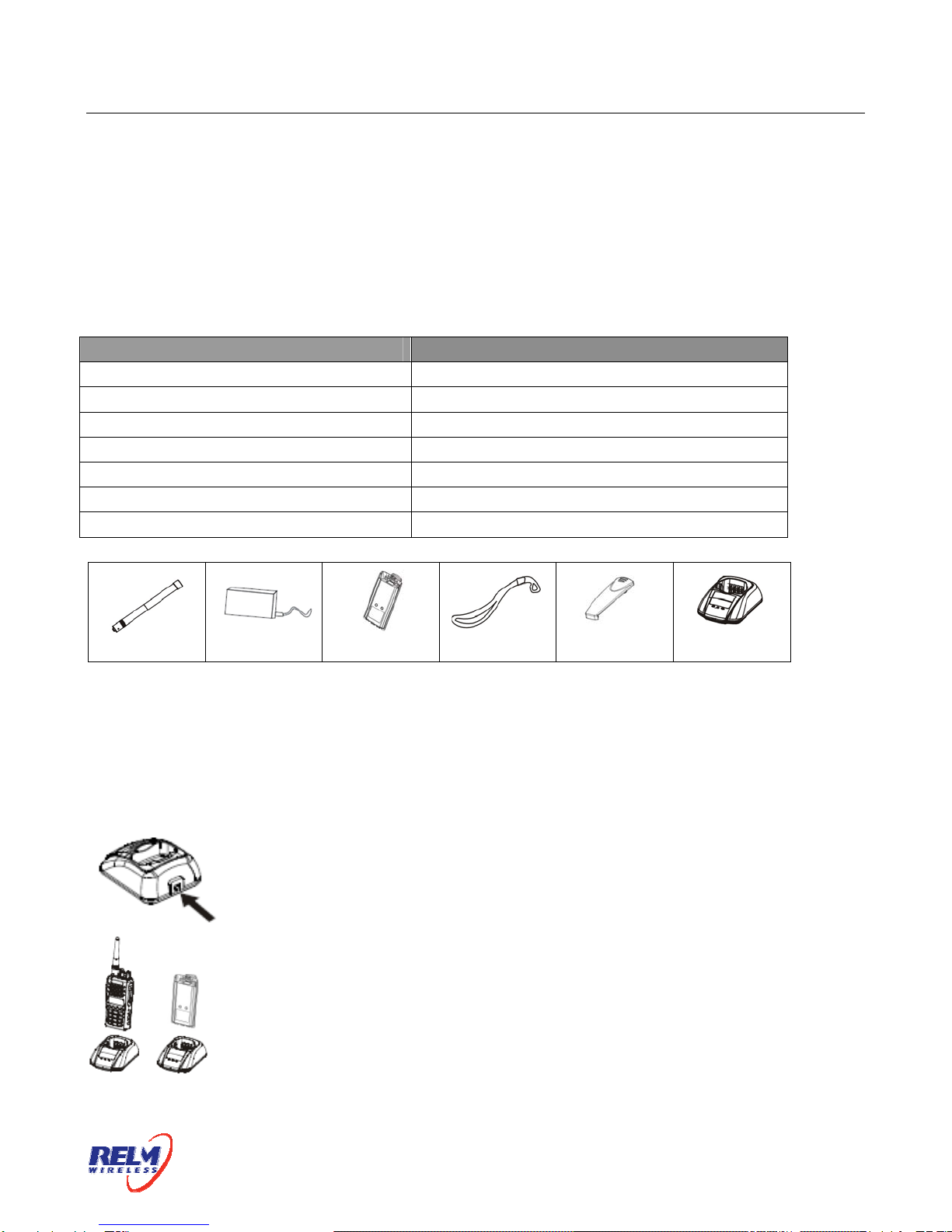
The performance will be at the best condition if you remove the battery when the green
indicator is on. Then remove the power adaptor from the wall outlet.
The charger will enter the protection mode when the yellow indicator flashes, which means the
temperature or the circuit is abnormal. Do not charge the battery at this moment, just remove
the battery and turn off the power of the charger.
Notes:
* The battery is not fully charged in the factory. Before the initial use, please charge the new
battery.
* When you charge the battery the first time or after long time storage (2 months), several
times of charging is needed. Make sure the battery is charged at least once every three
months.
* Do not charge the battery again if it is charged fully or not in the low-pressure warning mode,
otherwise, it will have bad effects on its life and performance. Remove the battery from the
charger after charging.
* There is a protection circuit in KB-36C battery, so the power will be cut off at too low power.
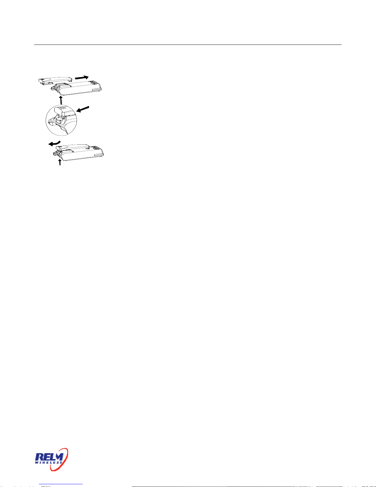
Installing/Removing the battery pack
To install the battery pack:
Match the 3 bulges of the battery pack with the corresponding slots at
the rear bottom of the transceiver.
To install the battery pack:
Then firmly press the battery pack downwards to lock it in place
until a click is heard.