REMKO MXD 204 User manual

Operating and
installation instructions
Read the instructions prior to performing any task!
REMKO MXD series
MXD 204, MXD 264, MXD 354, MXD 524
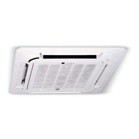
Ceiling cassettes for cooling and heating
0219-2019-04 Edition 1, en_GB

R32
Refrigerant
Translation of the original
Read these operating instructions carefully before commis-
sioning / using this device!
These instructions are an integral part of the system and must
always be kept near or on the device.
Subject to modifications; No liability accepted for errors or mis-
prints!

Table of contents
1 Safety and usage instructions............................................................................................................. 4
1.1 General safety notes....................................................................................................................... 4
1.2 Identification of notes...................................................................................................................... 4
1.3 Personnel qualifications.................................................................................................................. 4
1.4 Dangers of failure to observe the safety notes................................................................................ 5
1.5 Safety-conscious working............................................................................................................... 5
1.6 Safety instructions for the operator................................................................................................. 5
1.7 Safety notes for installation, maintenance and inspection ............................................................. 5
1.8 Unauthorised modification and changes......................................................................................... 6
1.9 Intended use................................................................................................................................... 6
1.10 Warranty........................................................................................................................................ 6
1.11 Transport and packaging............................................................................................................... 6
1.12 Environmental protection and recycling........................................................................................ 7
2 Technical data........................................................................................................................................ 8
2.1 Unit data.......................................................................................................................................... 8
2.2 Unit dimensions .............................................................................................................................. 9
3 Design and function............................................................................................................................ 10
3.1 Unit description............................................................................................................................. 10
4 Operation............................................................................................................................................. 11
4.1 General notes................................................................................................................................ 11
4.2 Display on indoor unit.................................................................................................................... 11
4.3 Keys on the remote control........................................................................................................... 12
5 Installation instructions for qualified personnel.............................................................................. 18
6 Installation........................................................................................................................................... 19
7 Condensate drainage connection and safe drainage...................................................................... 22
8 Electrical wiring................................................................................................................................... 23
8.1 General information....................................................................................................................... 23
8.2 Unit connection............................................................................................................................. 23
8.3 Electrical wiring diagram............................................................................................................... 24
8.4 Electrical drawings........................................................................................................................ 25
8.5 Connection of a superordinate controller provided by the customer............................................. 26
9 Commissioning................................................................................................................................... 27
10 Shut-down............................................................................................................................................ 28
11 Troubleshooting and customer service ........................................................................................... 29
12 Care and maintenance........................................................................................................................ 32
13 Exploded view of the unit and spare parts list................................................................................. 34
13.1 Exploded view of the unit ........................................................................................................... 34
13.2 Spare parts list............................................................................................................................ 35
14 Index..................................................................................................................................................... 36
3

1 Safety and
usage instructions
1.1 General safety notes
Carefully read the operating manual before com-
missioning the units or their components for the
first time. It provides useful tips and notes such as
hazard warnings to prevent injury and material
damage. Failure to follow the directions in this
manual can endanger persons, the environment
and the equipment itself or its components and will
void any claims for liability.
Store this manual and the information required for
the operation of this system (e.g. refrigerant data-
sheet) in the vicinity of the unit.
The refrigerant used in the system is flammable. If
applicable, observe the local safety conditions.
Warning of inflammable substances!
1.2 Identification of notes
This section provides an overview of all important
safety aspects for proper protection of people and
safe and fault-free operation.The instructions and
safety notes contained within this manual must be
observed in order to prevent accidents, personal
injury and material damage.
Notes attached directly to the units must be
observed in their entirety and be kept in a fully
legible condition.
Safety notes in this manual are indicated by sym-
bols. Safety notes are introduced with signal words
which help to highlight the magnitude of the danger
in question.
DANGER!
Contact with live parts poses an immediate
danger of death due to electric shock. Damage
to the insulation or individual components may
pose a danger of death.
DANGER!
This combination of symbol and signal word
warns of a situation in which there is immediate
danger, which if not avoided may be fatal or
cause serious injury.
WARNING!
This combination of symbol and signal word
warns of a potentially hazardous situation,
which if not avoided may be fatal or cause
serious injury.
CAUTION!
This combination of symbol and signal word
warns of a potentially hazardous situation,
which if not avoided may cause injury or mate-
rial and environmental damage.
NOTICE!
This combination of symbol and signal word
warns of a potentially hazardous situation,
which if not avoided may cause material and
environmental damage.
This symbol highlights useful tips and recom-
mendations as well as information for efficient
and fault-free operation.
1.3 Personnel qualifications
Personnel responsible for commissioning, opera-
tion, maintenance, inspection and installation must
be able to demonstrate that they hold a qualifica-
tion which proves their ability to undertake the
work.
REMKO MXD series
4

1.4 Dangers of failure to observe
the safety notes
Failure to observe the safety notes may pose a risk
to people, the environment and the units. Failure to
observe the safety notes may void any claims for
damages.
In particular, failure to observe the safety notes
may pose the following risks:
nThe failure of important unit functions.
nThe failure of prescribed methods of mainte-
nance and repair.
nDanger to people on account of electrical and
mechanical effects.
1.5 Safety-conscious working
The safety notes contained in this manual, the
existing national regulations concerning accident
prevention as well as any internal company
working, operating and safety regulations must be
observed.
1.6 Safety instructions
for the operator
The operational safety of the units and compo-
nents is only assured providing they are used as
intended and in a fully assembled state.
nThe units and components may only be set up,
installed and maintained by qualified per-
sonnel.
nProtective covers (grills) over moving parts
must not be removed from units that are in
operation.
nDo not operate units or components with
obvious defects or signs of damage.
nContact with equipment parts or components
can lead to burns or injury.
nThe units and components must not be
exposed to any mechanical load, extreme
levels of humidity or extreme temperatures.
nRooms in which refrigerant may escape shall
be adequately aerated and ventilated. Other-
wise, a risk of suffocation or fire exists.
nDo not leave children unsupervised when close
to the system.
nCommissioning must be performed by author-
ised specialists exclusively. Deficient commis-
sioning may lead to water leaks, electric
shocks or fire. Commissioning must take place
as described in the user manual.
nOnly instruct authorised specialist personnel to
perform maintenance or servicing.
nThe system is filled with a flammable refrig-
erant. Never thaw any frozen unit components
independently!
nDo not operate any further devices that pro-
duce high heat or naked flames in the same
room.
nAll housing parts and unit openings, e.g. air
inlets and outlets, must be kept clear.
nThe units must be inspected by a service tech-
nician to ensure that they are safe to use and
fully functional at least once yearly. Visual
inspections and cleaning may be performed by
the operator when the units are disconnected
from the mains.
1.7 Safety notes for installation,
maintenance and inspection
nThe refrigerant R32 used in the system is flam-
mable. If applicable, observe the local safety
conditions.
nKeep the cooling circuit clear of other gases
and foreign substances. Only fill the cooling cir-
cuit with the refrigerant R32.
nOnly use the accessories, components and
appropriately marked parts provided. The use
of non-standardised components may result in
water leaks, electric shocks and fire.
nOnly install and store the units in rooms larger
than 4 m2. With a failure to comply, leaks may
result in the room filling with a flammable mix-
ture!
The minimum room size of 4 m2 required for
installation and storage pertains to the basic fill
quantity of the unit. This varies according to the
installation type and total fill quantity of the
system. The calculation must take place in
accordance with valid DIN standards. Make
sure that the installation site is suitable for safe
unit operation.
nOnly mount the unit components on structurally
suitable brickwork.
nThe units must not be installed in rooms in
which further devices that produce heat are
operated (heaters, open hearths).
nMake sure the installation room is sufficiently
ventilated.
nInterventions in the cooling circuit are only pos-
sible after completely draining the refrigerant.
Never solder or grind unit components!
nNote that refrigerant may be odourless.
nNever operate the air conditioning unit in a
humid room, such as a bathroom or laundry
room. If the humidity is too high, this can cause
short circuits on electrical parts.
nThe product must be correctly earthed at all
times, otherwise it may induce electric shocks.
nAttach the condensate drain as described in
the operating manual. The inadequate
drainage of condensate can lead to water
damage in your apartment.
5
nAll persons who intervene in the cooling circuit
must hold a valid certificate from the chamber
of industry and commerce, which confirms their
ability to work with refrigerant.
nAppropriate hazard prevention measures must
be taken to prevent risks to people when per-
forming installation, repair, maintenance or
cleaning work on the units.
nThe setup, connection and operation of the
units and its components must be undertaken
in accordance with the usage and operating
conditions stipulated in this manual and comply
with all applicable regional regulations.
nRegional regulations and laws as well as the
Water Ecology Act must be observed.
nThe power supply should be adapted to the
requirements of the units.
nUnits may only be mounted at the points pro-
vided for this purpose at the factory. The units
may only be secured or mounted on stable
structures, walls or floors.
nThe units and components should not be oper-
ated in areas where there is a heightened risk
of damage. Observe the minimum clearances.
nThe units and components must be kept at an
adequate distance from flammable, explosive,
combustible, abrasive and dirty areas or
atmospheres.
nSafety devices may not be modified or
bypassed.
nThe connection of the indoor unit must be
established as a permanent connection; a
detachable, reusable connection is not permis-
sible.
1.8 Unauthorised modification
and changes
Modifications or changes to units and components
are not permitted and may cause malfunctions.
Safety devices may not be modified or bypassed.
Original replacement parts and accessories
authorised by the manufactured ensure safety. The
use of other parts may invalidate liability for
resulting consequences.
1.9 Intended use
Depending on the model, the units and the addi-
tional fittings with which they are equipped are only
intended to be used as an air-conditioner for the
purpose of cooling or heating the air in an
enclosed space.
Any different or additional use is a non-intended
use. The manufacturer/supplier assumes no lia-
bility for damages arising from a non-intended use.
The user bears the sole risk in such cases.
Intended use also includes working in accordance
with the operating and installation instructions and
complying with the maintenance requirements.
The threshold values specified in the technical
data must not be exceeded.
1.10 Warranty
For warranty claims to be considered, it is essential
that the ordering party or its representative com-
plete and return the "certificate of warranty" to
REMKO GmbH & Co. KG at the time when the
units are purchased and commissioned.
The warranty conditions are detailed in the "Gen-
eral business and delivery conditions". Further-
more, only the parties to a contract can conclude
special agreements beyond these conditions. In
this case, contact your contractual partner in the
first instance.
1.11 Transport and packaging
The devices are supplied in a sturdy shipping con-
tainer. Please check the equipment immediately
upon delivery and note any damage or missing
parts on the delivery and inform the shipper and
your contractual partner. For later complaints can
not be guaranteed.
WARNING!
Plastic films and bags etc. are dangerous
toys for children!
Why:
- Leave packaging material are not around.
- Packaging material may not be accessible to
children!
REMKO MXD series
6

1.12 Environmental protection
and recycling
Disposal of packaging
All products are packed for transport in environ-
mentally friendly materials. Make a valuable contri-
bution to reducing waste and sustaining raw mate-
rials. Only dispose of packaging at approved
collection points.
Disposal of equipment and components
Only recyclable materials are used in the manufac-
ture of the devices and components. Help protect
the environment by ensuring that the devices or
components (for example batteries) are not dis-
posed in household waste, but only in accordance
with local regulations and in an environmentally
safe manner, e.g. using certified firms and recy-
cling specialists or at collection points.
7

2 Technical data
2.1 Unit data
Series MXD 204 MXD 264 MXD 354 MXD 524
Operating mode Ceiling cassette for inverter multisplit outdoor units
for cooling and heating
Nominal cooling output 1) kW 2.05 2.64 3.51 5.27
Nominal heat capacity 2) kW 2.34 3.22 3.81 6.00
Application area (room volume),
approx. m360 80 110 160
Adjustment range, room temperature °C +17 to +30
Operating range °C +17 to +32
Refrigerant R32
Operating pressure max. / per
cooling cycle kPa 4200/1500
Air flow volume per stage m3/h 450/500/580 450/530/650 500/650/800
Sound pressure level per stage 3) dB (A) 35/38/42 33/36/39 34/37/41 36/42/48
Sound power (turbo mode) dB (A) 53 58 59
Power supply V/Ph/Hz 230/1~/50
Enclosure class IP X 0
Electrical rated power consumption,
cooling 1) W 40 102
Electrical rated power consumption,
heating 2) W 40 102
Electrical rated current consumption,
cooling 1) A 0.18 0.44
Electrical rated current consumption,
heating 2) A 0.18 0.44
Refrigerant injection pipe connection Inches
(mm) 1/4 (6.35) 1/4 (6.35) 1/4 (6.35) 1/4 (6.35)
Refrigerant suction pipe connection Inches
(mm) 3/8 (9.52) 3/8 (9.52) 3/8 (9.52) 1/2 (12.70)
Condensate drainage connection mm 25 25 25 25
Condensate pump, flow rate, max. mm WS 500
REMKO MXD series
8

Series MXD 204 MXD 264 MXD 354 MXD 524
Cassette dimensions
Length mm 570 570 570 570
Width mm 570 570 570 570
Depth mm 260 260 260 260
Cover dimensions
Length mm 647 647 647 647
Width mm 647 647 647 647
Depth mm 50 50 50 50
Weight kg 15.0 16.0 18.0
Cover weight kg 2.5 2.5 2.5 2.5
Serial number 1324... 1325... 1326... 1327...
EDP no. 1623390 1623392 1623394 1623396
1) Air intake temperature TK 27 °C / FK 19 °C, outside temperature TK 35 °C, FK 24 °C, max. air flow
volume, 5 m pipe length
2) Air intake temperature TK 20 °C, outside temperature TK 7 °C, FK 6 °C, max. air flow volume,
5 m pipe length
3) Distance 1 m free field
For information on energy efficiency, see the operating instructions for the relevant outdoor unit
2.2 Unit dimensions
175
570
215
260
28030
65
415
570
40
50
140
545
647
523
647
13
24
Fig. 1: Dimensions MXD 204-524 (all measurements in mm)
1: Fresh air connection
2: Implementing the electrical control line
3: Condensate drainage connection
4: Refrigerant piping connection
9

3 Design and function
3.1 Unit description
The indoor unit is used to extract heat from the
indoor room being cooled. The outdoor unit then
expels this heat to the outside.
If combined heating/cooling units are operated as
heaters, the heat absorbed by the outdoor unit can
be discharged by the indoor unit into the room
being heated.
The unit series has the "Heating" priority, i.e. the
units that are in heating or automatic mode can
switch off other units in the system that are running
in cooling mode.
The unit is designed to be mounted high up on
indoor area.
It is operated by an infrared remote control.
The indoor unit consists of a fin evaporator, evapo-
rator fan, controller and condensate tray. The
indoor unit can be combined with REMKO outdoor
units from the MVT 603 DC, 903 DC, 1053 DC and
1403 DC range that provide sufficient combination
options. The outdoor unit is controlled by the con-
troller in the indoor unit.
A cabled remote control and a condensate pump
are available as accessories.
B
A
4
3
5
6
1a 1b
2
7b
3 3
7a
8b8a
9b9a
Fig. 2: System layout (in the example: MVT 903
DC with 2 MXD 354)
A: Outdoor area
B: Indoor area
1 a,b: Indoor units
2: Outdoor unit
3: Condensate drainage line
4: Condenser fan
5: Power supply
6: Shut-off valve
7 a,b: Suction pipes
8 a,b: Injection pipes
9 a,b: Control lines
Refrigerant piping is used to connect the indoor
unit to the outdoor unit.
2
1
4
3
Fig. 3: Cooling cycle schematic
1: Evaporator
2: Evaporator fan
3: Suction pipe connection
4: Injection pipe connection
REMKO MXD series
10

4 Operation
4.1 General notes
The indoor unit is easily operated using the
standard infrared remote control. The indoor unit
beeps to acknowledge the correct transmission of
data. If it is not possible to program the indoor unit
with the remote control, then it can also be man-
ually operated. The indoor unit can also be oper-
ated via an optional cabled remote control.
Manual mode
The indoor units can be put into operation man-
ually. Press the "MANUAL" key on the cover's
receiver unit to first activate automatic mode and
then cooling mode. Pressing the button a third time
switches the unit off. Pressing the button again
switches back to automatic mode. The unit that
has cooling mode activated manually becomes the
leading unit within the entire system. In manual
mode, the following settings apply:
Cooling mode: 24 °C, fan speed: AUTO
Heating mode: 26 °C, fan speed: AUTO
Press a key on the infrared remote control to inter-
rupt manual mode.
Infrared remote control
The infrared remote control sends the programmed
settings a distance of up to 6 m to the receiver of
the indoor unit. Data will only be received correctly
if the remote control is pointed at the receiver and
no objects are obstructing the transmission path.
First insert the supplied batteries (2 each, type
AAA) into the remote control. To do so, pull off the
flap of the battery compartment and insert the bat-
teries correctly by polarisation (see marks).
max. 6 m
<block y.linktarget="true" y.validity.allowed="true" y.keep.together.within.page="false" ip="none" y.id="ID_79026f118af378b2c0a80aa000dde74d" y.validity.mode="positive" y.io.validity.mode="positive"><title y.commentable="true" y.id="ID_2df61a8af378b2c0a80aa0007c9fdc" y.linktarget="true" y.validity.allowed="true" y.validity.mode="positive" y.io.validity.mode="positive"><?xm-replace_text {Block title}?></title><p y.validity.allowed="true" y.commentable="true" y.id="ID_8ad17fa18af378b2c0a80aa001e35c28" y.validity.mode="positive">Das Innengerät wird komfortabel mit der serienmäßigen Infrarot-Fernbedienung bedient. Die ordnungsgemäße Datenübermittlung wird vom Innengerät mit einem Signalton quittiert. Sollte eine Programmierung über die
Infrarot-Fernbedienung nicht möglich sein, kann das Innengerät auch manuell bedient werden. Optional kann das Innengerät auch mit einer Kabelfernbedienung bedient werden.</p></block><block y.linktarget="true" y.validity.allowed="true" y.keep.together.within.page="true" ip="none" y.id="ID_adea262699646b1ac0a80aa00124eb02" y.validity.mode="positive" y.io.validity.mode="positive"><title y.commentable="true" y.id="ID_822fed5d99646b1ac0a80aa000c0eb90" y.linktarget="true" y.validity.allowed="true" y.validity.mode="positive" y.io.validity.mode="positive">Manuelle Bedienung</title><xe y.id="ID_72092e01cc69eeb1c0a80aa0001072e8"><primary y.commentable="true" y.id="ID_f2b45117cc69eeb1c0a80aa001e812b8">Manuelle Bedienung</primary></xe><p y.validity.allowed="true" y.commentable="true" y.id="ID_59dea67f99646b1ac0a80aa001a94073" y.validity.mode="positive">Die Innengeräte können manuell in Betrieb genommen werden.
Durch Betätigen der Taste "MANUAL" am Empfangsteil der Abdeckung
wird erst der Automatikmodus, dann der Kühlmodus aktiviert. Das dritte Betätigen schaltet das Gerät aus. Ein erneutes Betätigen wechselt zurück zum Automatikmodus.
Innerhalb der gesamten Anlage wird das Gerät, welches den manuell eingestellten Kühlmodus besitzt zum Führungsgerät.
Im manuellen Betrieb gelten die folgenden Einstellungen:</p><p y.validity.allowed="true" y.commentable="true" y.id="ID_3a9a283d99646b1ac0a80aa000c67f7f" y.validity.mode="positive">
Kühlbetrieb: 24 °C,
Ventilatorgeschwindigkeit: AUTO
</p><p y.validity.allowed="true" y.commentable="true" y.id="ID_3d36471699646b1ac0a80aa001dc8c12" y.validity.mode="positive">Heizbetrieb: 26 °C,
Ventilatorgeschwindigkeit: AUTO
</p><p y.validity.allowed="true" y.commentable="true" y.id="ID_bc86e04299646b1ac0a80aa000700630" y.validity.mode="positive">Durch Betätigen einer Taste der Infrarot-Fernbedienung wird der
manuelle Betrieb unterbrochen.</p><p y.validity.allowed="true" y.commentable="true" y.id="ID_960d3e6fe104f4f1c0a80aa0017e7896" y.validity.mode="positive"><b>Infrarot-Fernbedienung</b></p><xe y.id="ID_533d60fbcc69eeb1c0a80aa00124f630"><primary y.commentable="true" y.id="ID_8b358666cc69eeb1c0a80aa0019ef0e1">Infrarot-Fernbedienung</primary></xe><p y.validity.allowed="true" y.commentable="true" y.id="ID_01dbfb2899646b1ac0a80aa001c22414" y.validity.mode="positive">
Die Infrarot-Fernbedienung sendet die programmierten Einstellungen in einem Abstand von bis zu 6 m zum Empfangsteil des Innengerätes. Ein ungestörter Empfang der Daten ist nur möglich, wenn die Fernbedienung auf das Empfangsteil gerichtet und keine Gegenstände die Übertragung behindern.
</p><p y.validity.allowed="true" y.commentable="true" y.id="ID_f84708fc99646b1ac0a80aa000cea521" y.validity.mode="positive">Vorbereitend sind die im Lieferumfang bendlichen Batterien
(2 Stück, Typ AAA) in die Fernbedienung einzusetzen. Ziehen Sie dazu die Klappe des Batteriefachs ab und setzen die Batterien polungsrichtig ein (siehe Markierung).</p></block><block y.linktarget="true" y.validity.allowed="true" ip="none" y.id="ID_9cb8e18699646b1ac0a80aa000a63989" y.keep.together.within.page="false" y.validity.mode="positive" y.io.validity.mode="positive"><gure size="margin" y.linktarget="true" y.validity.allowed="true" y.commentable="true" ip="none" y.id="ID_b1c62b99ea33cfc0a80aa00177114f" y.validity.mode="positive"><img y.io.id="a7ef1e92cc0463e3c0a80aa00099319e" y.io.version="1" y.io.language="--" y.io.variant="--" y.io.name="COS-FB-Maximaler-Abstand" y.io.format="PNG72" y.reftype="bild" y.ref.io.types="me-imggif, me-imgjpeg, me-imgpng, me-imgsvg, me-imgti, me-imgpdf, me-imgeps, me-imgdes" y.io.validity.mode="positive" y.validity.mode="positive" yhref="https://xml24.kothes.de:443/cmsweb/view/a7ef1e92cc0463e3c0a80aa00099319e/1/--/--/PNG72/previewtrue/745" y.io.owner="pschimczik" y.io.status="Approved"/><subtitle y.commentable="true" y.id="ID_45b64fd899ea33cfc0a80aa000118fa1">Maximaler Abstand</subtitle></gure></block><block y.linktarget="true" y.validity.allowed="true" y.keep.together.within.page="false" ip="none" y.id="ID_9303000c99ea33cfc0a80aa000ec972a" y.validity.mode="positive" y.io.validity.mode="positive"><note-ref y.io.id="c3fcca3999e7c4d7c0a80aa00075e61d" y.io.version="1" y.io.language="de" y.io.variant="DE" y.io.name="Störungen werden codiert angezeigt" y.reftype="text" y.validity.allowed="true" y.id="ID_cc37889a99ea33cfc0a80aa000b86398" y.ref.io.types="me-note" y.validity.mode="positive"><note y.validity.allowed="true" y.id="ID_6aafc54d99e7c4d7c0a80aa001a18c" y.io.id="c3fcca3999e7c4d7c0a80aa00075e61d" y.io.version="1" y.io.language="de" y.io.variant="DE" y.io.format="" y.commentable="true" y.validity.mode="positive" y.io.validity.mode="positive" y.io.owner="pschimczik" y.io.status="Approved"><title y.commentable="true" y.id="ID_cab1857499e7c4d7c0a80aa001c6fcb0" y.linktarget="true" y.validity.allowed="true" y.validity.mode="positive" y.io.validity.mode="positive"><?xm-replace_text {Note title}?></title><p y.validity.allowed="true" y.commentable="true" y.id="ID_5f147d5399e7c4d7c0a80aa000f79d44" y.validity.mode="positive">Störungen werden codiert
angezeigt
(siehe Kapitel Störungsbeseitigung und Kundendienst).
</p></note></note-ref></block><block y.linktarget="true" y.validity.allowed="true" y.keep.together.within.page="false" ip="none" y.id="ID_4889bf3299ea33cfc0a80aa00192ab32" y.validity.mode="positive" y.io.validity.mode="positive"><notice-ref y.io.id="6ef454f799e959f5c0a80aa0017cf664" y.io.version="1" y.io.language="de" y.io.variant="DE" y.io.name="Entladene Batterien ersetzen" y.reftype="text" y.validity.allowed="true" y.id="ID_c3b85e1999ea33cfc0a80aa000257b18" y.ref.io.types="me-notice" y.validity.mode="positive"><notice y.validity.allowed="true" y.id="ID_12c4b32999e959f5c0a80aa001b1843f" y.io.id="6ef454f799e959f5c0a80aa0017cf664" y.io.version="1" y.io.language="de" y.io.variant="DE" y.io.format="" y.commentable="true" y.validity.mode="positive" y.io.validity.mode="positive" y.io.owner="pschimczik" y.io.status="Approved"><title y.commentable="true" y.id="ID_0a56f35d99e959f5c0a80aa0016164c4" y.linktarget="true" y.validity.allowed="true" y.validity.mode="positive" y.io.validity.mode="positive"><?xm-replace_text {Notice title}?></title><p y.validity.allowed="true" y.commentable="true" y.id="ID_5d6f9c5699e959f5c0a80aa0011e84" y.validity.mode="positive">Ersetzen Sie entladene Batterien sofort durch einen neuen Satz, da sonst die Gefahr des Auslaufens besteht. Bei längeren Außerbetriebnahmen empehlt es sich die Batterien zu entfernen.</p></notice></notice-ref></block><block y.linktarget="true" y.validity.allowed="true" y.keep.together.within.page="false" ip="none" y.id="ID_3fa8dc8f7c8aeaedc0a80aa001a42c28" y.validity.mode="positive" y.io.validity.mode="positive"><note-ref y.io.id="bd677a507c893df9c0a80aa0006b7af7" y.io.version="1" y.io.language="de" y.io.variant="DE" y.io.name="Energie sparen mittels Stand-by-Modus" y.reftype="text" y.validity.allowed="true" y.id="ID_30ae5ea47c8aeaedc0a80aa0014f3168" y.ref.io.types="me-note" y.validity.mode="positive"><note y.validity.allowed="true" y.commentable="true" y.id="ID_cb6774c17c893df9c0a80aa000def2a8" y.io.id="bd677a507c893df9c0a80aa0006b7af7" y.io.version="1" y.io.language="de" y.io.variant="DE" y.io.format="" y.validity.mode="positive" y.io.validity.mode="positive" y.io.owner="pschimczik" y.io.status="Approved"><title y.commentable="true" y.id="ID_8afa74477c893df9c0a80aa0010d2f89" y.linktarget="true" y.validity.allowed="true" y.validity.mode="positive" y.io.validity.mode="positive"><?xm-replace_text {Note title}?></title><p y.validity.allowed="true" y.commentable="true" y.id="ID_4473aa437c893df9c0a80aa000abf90b" y.validity.mode="positive">Helfen Sie mit, Energieverbräuche im Stand-By-Betrieb einzusparen! Wird das Gerät, die Anlage oder die Komponente nicht verwendet, empfehlen wir eine Unterbrechung der Spannungsversorgung.
Der Sicherheit dienende Komponenten unterliegen nicht unserer Empfehlung!</p></note></note-ref></block>
Fig. 4: Maximum distance
Alarms are indicated by a code (see chapter
Troubleshooting and customer service).
NOTICE!
Immediately replace flat batteries with a new
set, otherwise there is a risk of leakage. It is
recommended that the batteries are removed if
the equipment is shut down for longer periods.
Help save on energy consumption in stand-by
mode! If the device, system or component is not
in use, we recommend disconnecting the power
supply. Components with a safety function is
excluded from our recommendation!
4.2 Display on indoor unit
Display on indoor unit
The LED indicators illuminate to indicate the set-
tings:
OPERATION LED green = unit switched on
TIMER LED yellow = timer programmed
DEF/FAN LED red = defrosting active/recirculation
mode
ALARM LED red = alarm present
2
1
4
6
3
5
Fig. 5: Display on the unit
1: Unit for receiving signals from the remote con-
trol
2: Operation display
3: Timer indicator
4: Manual operation key
5: Defrosting fan
6: Malfunction indication
11

4.3 Keys on the remote control
6
8
11
147
9
10
12
13
2
1
4
3
5
Fig. 6: Keys on the remote control
1
"ON/OFF" key
Press this key to switch the air conditioning unit on
and off.
2
"MODE" key
Operating mode selection. This key is used to set
the desired operating mode. The automatic,
cooling, dehumidification, heating and recirculation
modes are available.
3
"FAN" key
Fan speed Use this key to select the desired fan
speed. The automatic, low, medium and high func-
tions are available. Note: In the dehumidification
operating mode, the fan speed cannot be set man-
ually.
4
"SLEEP" key
Activates/deactivates the "SLEEP" function.
Pressing this key will automatically increase or
decrease the target temperature by 1 °C within an
hour in cooling and heating mode respectively.
Press this key to maintain the most convenient
temperature and save energy. This function is only
available in "Cooling", "Heating" and "Auto" modes.
If the unit is working in "SLEEP" mode, this activity
is interrupted by pressing the "MODE", "FAN",
"Speed" or "ON/OFF" keys.
5
"FRESH" key (without function)
6
"TURBO" key (without function)
7
"SELF CLEAN" key (without function)
8
"UP ARROW" and "DOWN ARROW" keys
Press this key to increase the setpoint in steps of
1 °C up to a maximum of 30°C.
Press this key to decrease the setpoint in steps of
1°C to a minimum of 17°C.
9
„SILENCE/FP“ key
Activates/deactivates the silent mode. Pressing the
key for longer than 2 seconds activates the unit's
frost protection function.
In silent unit mode, the compressor runs at a lower
frequency, and the indoor unit fan rotates at a
slower speed. This obtains particularly silent unit
operation.
The frost protection function can only be activated
in heating mode. The unit operates with a fixed
setpoint of 8°C. The indoor unit displays "FP".
Pressing the ON/OFF, SLEEP, FP, Mode, FAN or
up or down arrow key, the frost protection function
is deactivated. Press the this key to activate the
unit start delay time.
Note please!
Both functions are not available when con-
necting to the MVT unit series!
REMKO MXD series
12

10
"TIMER ON" key
This key initiates the automatic switch-on time for
the unit. Each press of this key increases the delay
time by 30 minutes. When the set time on the dis-
play exceeds 10.0, each press of the button
increases the set time by 60 minutes. To deacti-
vate the delay time, set the time to 0.0.
11
"TIMER OFF" key
This key can be used to program the delayed
switch-off time. Each press of this key increases
the switch-off time by 30 minutes. When the set
time on the display exceeds 10.0, each press of
the button increases the set time by 60 minutes. To
deactivate the switch-off time, set the time to 0.0
12
3-D swing mode
Press this key to start or stop the swing mode.
With the 2-point key, you can adjust the horizontal
fin on the left side. Press this key once to change
the angle by 6 degrees. Pressing the key for 2 sec-
onds stops the swing function. When the swing
function is stopped, LC appears on the display for
three seconds.
13
"FOLLOW ME" key
This key can be used to activate/deactivate the
FOLLOW ME function. In this mode, the room tem-
perature is measured on the remote control. This
sends a signal to the indoor unit every 3 minutes. If
the remote control does not send a signal to the
indoor unit for 7 minutes, this mode is automati-
cally deactivated.
14
"LED" key
This activates/deactivates the display on the indoor
unit.
Indicators on the LCD
2
1
4
36
9
8
10
5
7
11
13 12
Fig. 7: Indicators on the LCD
1: Mode display - shows the current operating
modes including Auto ( ), Cooling( ), Dehu-
midifying ( ), Heating ( ), Fan ( ) and back
to Auto ( ) mode.
2: Signal transmission symbol. This symbol
appears when signals are being transmitted
from the remote control to the indoor unit.
3: ON/OFF symbol. This symbol appears when
the "ON/OFF" key is pressed. Pressing this
key again causes the indicator to go out.
4: TIMER ON symbol. This symbol appears
when TIMER ON is switched on.
5: ECO function (not available)
6: TIMER OFF symbol. This symbol appears
when TIMER OFF is switched on.
7: Battery status (weak)
8: Sleep symbol. This symbol appears when the
"Sleep" function is activated. Pressing this key
again causes the indicator to go out.
9: Temperature/Timer symbol. Shows the tem-
perature setting (-17°C~30°C). If "FAN" mode
is selected, the temperature setting is not dis-
played. In Timer mode, the ON and OFF set-
tings appear for the TIMER.
10: FOLLOW ME symbol. This symbol appears
when the "Follow me" function is activated.
11: Ion generator display active (optional)
12: Fan speed symbol. This is where the selected
fan speeds are displayed: AUTO (no indicator)
and the three fan speed settings: (slow),
(medium) and
(fast). The fan speed is set to "Automatic"
when either "Auto" or "Dehumidification" mode
is activated.
13: Silent mode active (optional)
13

The illustration of the LCD with all of the sym-
bols present is only intended to provide a
clearer overview. During operation, only those
symbols relevant to the respective functions
appear on the display.
Key functions
A symbol is shown on the display to indicate that
the settings are being transferred.
"Auto" mode
Make sure that the indoor unit is connected to the
power supply, and is switched on.
The operating mode indicator on the display of the
indoor unit begins to flash.
1. Press the "MODE"key to select "Auto" mode.
2. Press the "UP/DOWN"key to set the desired
temperature. The temperature can be set
between 17 and 30°C, in increments of 1°C.
3. Press the "ON/OFF"key to switch the air
conditioning unit on.
1
3
2
Fig. 8: "Auto" mode
In "automatic" mode, the cooling unit automati-
cally selects among cooling, recirculation and
heating operation and tries to reach the setpoint
set on the remote control
"Cooling", "Heating" and "Recirculation" mode
Make sure that the indoor unit is connected to the
power supply, and is switched on.
1. Press the "MODE"key to select from oper-
ating modes "Cooling", "Heating" or "Recircu-
lation".
2. Press the "UP/DOWN"key to set the desired
temperature. The temperature can be set
between 17 and 30°C, in increments of 1°C.
3. Press the "FAN"key to select from the four
fan speeds (Auto, slow, medium and fast).
4. Press the "ON/OFF"key to switch the air
conditioning unit on.
1
4
2
3
Fig. 9: "Cooling", "Heating" and "Recirculation"
mode
REMKO MXD series
14

"Dehumidification" mode
Make sure that the indoor unit is connected to the
power supply, and is switched on.
The operating mode indicator on the display of the
indoor unit begins to flash.
1. Press the "MODE"key to select "Dehumidi-
fying" mode.
2. The temperature setting on the remote con-
trol has no effect on unit operation.
3. Press the "ON/OFF"key to switch the air
conditioning unit on.
1
3
2
Fig. 10: "Dehumidification" mode
In "Dehumidification" mode, it is not possible to
set the fan speed. This is already controlled
automatically.
"Timer" mode
Press the "TIMER ON" key to set the "Auto on"
time and the "TIMER OFF" key to set the "Auto off"
time for the unit.
Setting the "Auto on" time
1. Press the "TIMER ON" key. The remote con-
trol shows "TIMER ON", the last "Auto on"
time setting and the symbol "H" appears on
the display. The unit is now ready to reset the
"Auto on" time and to start "TIMER ON"
mode.
2. Press the "TIMER ON" key again to set the
desired "Auto on" time. Each time the key is
pressed, the time is increased by half an
hour between 0 and 10 hours, and by an
hour between 10 and 24 hours.
3. Once these settings have been made, there
is a one second delay before the remote con-
trol transmits the signal to the indoor unit.
Then, after approx. two seconds, the "H"
symbol disappears from the LCD display, and
the set temperature appears again on the
display.
2
1
Fig. 11: "Timer" mode
15

Setting the "Auto off" time
1. Press the "TIMER OFF" key. The remote
control shows "TIMER OFF", the last "Auto
off" time setting and the symbol "H" appears
on the display. The unit is now ready to reset
the "Auto off" time and to stop "TIMER OFF"
mode.
2. Press the "TIMER OFF" key again to set the
desired "Auto off" time. Each time the key is
pressed, the time is increased by half an
hour between 0 and 10 hours, and by an
hour between 10 and 24 hours.
3. Once these settings have been made, there
is a one second delay before the remote con-
trol transmits the signal to the indoor unit.
Then, after approx. two seconds, the "H"
symbol disappears from the LCD display, and
the set temperature appears again on the
display.
–When Timer mode is selected, the remote
control automatically transfers the timer
signal to the indoor unit for the specified
period of time. Therefore, you should hold
the remote control in a location where it can
transfer the signal to the indoor unit without
interference.
–The effective operation for the time settings
by the remote control for the timer function
is restricted to the following settings:
0.5, 1.0, 1.5, 2.0, 2.5, 3.0, 3.5, 4.0, 4.5, 5.0,
5.5, 6.0, 6.5, 7.0, 7.5, 8.0, 8.5, 9.0, 9.5, 10,
11, 12, 13, 14, 15, 16, 17, 18, 19, 20, 21,
22, 23 and 24.
Example TIMER function settings
"TIMER ON" (Auto on mode)
Example:
You want the air conditioning unit to switch on six
hours from the time it was programmed.
1. Press the "TIMER ON" key. The last oper-
ating time setting for the timer, and the "H"
symbols, appear on the display.
2. Press the "TIMER ON" key until the desired
start time is shown in the "TIMER ON" area
on the remote control.
3. Wait for 3 seconds and the temperature
appears again in this area of the digital dis-
play. The "TIMER ON" indicator stays lit, and
this function is activated.
Start
Off
2 hours laterSet time
Fig. 12: "TIMER ON" example
"TIMER OFF" (Auto off mode)
Example:
You want the air conditioning unit to switch off 4
hours from the time it was programmed.
1. Press the "TIMER OFF" key. The last oper-
ating time setting for the timer, and the "H"
symbols, appear on the display.
2. Press the "TIMER OFF" key until "10H" is
shown in the "TIMER OFF" area on the
remote control.
3. Wait for 3 seconds and the temperature
appears again in this area of the digital dis-
play. The "TIMER OFF" indicator stays lit,
and this function is activated.
Stop
On
4 hours laterSet time
Fig. 13: "TIMER OFF" example
REMKO MXD series
16

Combined TIMER (setting "TIMER ON" and
"TIMER OFF" at the same time)
"TIMER OFF ð "TIMER ON"
(On ð Stop ð Start)
Example:
You want the air conditioning unit to switch off in
two hours from the time it was programmed, and
switch back on ten hours later.
1. Press the "TIMER OFF" key.
2. Press the "TIMER OFF" key again until the
desired stop time is shown in the "TIMER
OFF" area on the remote control.
3. Press the "TIMER ON" key.
4. Press the "TIMER ON" key again until "10H"
is shown in the "TIMER ON" area on the
remote control.
5. Wait for 3 seconds and the temperature
appears again in this area of the digital dis-
play. The "TIMER ON" and "TIMER OFF"
indicators stay lit, and this function is acti-
vated.
On
Set time
Stop
Start
2 hours later
after setting 10 hours later
after setting
Fig. 14: "TIMER OFF" / "TIMER ON" example
"TIMER ON ð "TIMER OFF"
(Off ð Start ð Stop)
Example:
You want the air conditioning unit to switch on in
two hours from the time it was programmed, and
switch back off five hours later.
1. Press the "TIMER ON" key.
2. Press the "TIMER ON" key again until "2.0H"
is shown in the "TIMER ON" area on the
remote control.
3. Press the "TIMER OFF" key.
4. Press the "TIMER OFF" key again until
"5.0H" is shown in the "TIMER OFF" area on
the remote control.
5. Wait for 3 seconds and the temperature
appears again in this area of the digital dis-
play. The "TIMER ON" and "TIMER OFF"
indicators stay lit, and this function is acti-
vated.
Off
Set time
Stop
Start
2 hours later
after setting 5 hours later
after setting
Fig. 15: "TIMER ON" / "TIMER OFF" example
17

SLEEP function
The sleep function saves energy while you sleep.
This function is activated by pressing the key on
the remote control. Press the key before going to
sleep. In cooling mode, the unit automatically
increases the set room temperature by 1 °C after 1
hour. After one more hour, the room temperature is
increased by an additional 1 °C. In heating mode,
the room temperature is decreased within the first
two hours of operation by 2°C. After 7 hours of unit
operation, the unit switches automatically off in
cooling and heating mode.
This function is not available in the recirculation
and dehumidification operating modes!
1
Fig. 16: "Sleep" function
Setpoint After 7 hours
unit OFF
1 hr 1 hr
Fig. 17: Sleep function
5 Installation instructions
for qualified personnel
Important notes prior to installation
Observe the operating manuals for the indoor unit
and the outdoor unit when installing the entire
system.
nTransport the unit in its original packaging as
close as possible to the installation location.
You avoid transport damage by doing so.
nCheck the contents of the packaging for com-
pleteness and check the unit for visible trans-
port damage. Report any damage immediately
to your contractual partner and the shipping
company.
nLift the unit on the corners and not on the
refrigerant or condensate drainage connec-
tions.
nThe refrigerant piping (injection and suction
pipe), valves and connections must be insu-
lated against vapour density. If necessary also
insulate the condensate drainage line.
nSelect an installation location which allows air
to freely flow through the air inlet and outlet
(see section "Minimum clearances").
nDo not install the unit in the immediate vicinity
of devices which generate intensive thermal
radiation. Installation in the vicinity of thermal
radiation reduces the unit output.
nInstall the refrigerant piping from the indoor unit
to the outdoor unit.
nSeal off open refrigerant piping with suitable
caps or adhesive strips to prevent the infiltra-
tion of moisture and never kink or compress
the refrigerant piping.
nOnly use the union nuts supplied with the
refrigerant piping. These should only be
removed shortly before connecting the refrig-
erant piping.
nCarry out all electrical wiring in accordance
with applicable DIN and VDE standards.
nEnsure the electrical cables are properly con-
nected to the terminals. Otherwise there is a
risk of fire.
nService openings should be provided in the
suspended ceiling to allow for maintenance
access.
Installation materials
The indoor unit is attached to the wall by a wall
bracket and 4 screws (to be provided by the cus-
tomer). Use the installation material provided to
complete the installation. Wall plugs, trapezoidal
sheet metal supports, steel profiles, fixing clamps
for refrigerant and condensate drainage lines (as
well as laying ducts) and connection fittings for
condensation pipes must be provided by the cus-
tomer.
REMKO MXD series
18

Selection of installation location
The indoor unit is specifically designed for hori-
zontal mounting in suspended ceilings with Euro-
raster dimensions. However, it can also be
installed in suspended ceilings with different
dimensions. Take into account the installation
height of the equipment.
Minimum clearances
Observe the minimum clearances to allow access
for maintenance and repair work and facilitate
optimum air distribution.
300 300
300
300 300
Fig. 18: Minimum clearances MXD 204-524 (all
measurements in mm)
6 Installation
NOTICE!
Installation should only be performed by author-
ised specialists.
Unit installation
The unit is mounted with the cover face down on
four threaded rods. Take into account the ceiling
grid and any other installations.
1. Use the dimensions of the ceiling cassette to
mark the fixing points for the threaded rods
on structural parts approved to support the
static load above the suspended ceiling
(Fig. 19).
2. Fit the indoor unit onto the threaded rods and
use the lower nuts to level the unit (Fig. 20).
3. Adhere to a ceiling clearance of at least 35
mm. Connect the refrigerant piping, electrical
cables and condensate drainage line to the
indoor unit as described below.
4. Check again that the unit is level.
5. The final task is to tighten the counter nuts
and attach the cover.
522
522
Fig. 19: Hooking in the unit (MXD 204-524)
19

1
1
A
B
Fig. 20: Hooking in the unit (MXD 204-524)
1: Structural component
A: Min. 35 mm
B: 265 mm
A
Fig. 21: Fastening the unit
A: Distance A
MXD 204-524
Distance A 70 mm
Suspended unit 545 mm x 525 mm
Connection of refrigerant piping
The refrigerant piping connection provided by the customer takes place on one corner of the unit, inside the
suspended ceiling. It may be necessary to fit a reducing or extending adapter to the outdoor unit. These fit-
tings are included with the outdoor unit as an accessory kit. Once installed, the connections should be insu-
lated to make them vapour diffusion proof.
Power Outdoor unit
Refrig-
erant
piping
Indoor unit MXD 204-524
Indoor unit Connec-
tion Reducer / flared adapter
Refrig-
erant
piping
Reducer / flared adapter Connec-
tion
IP SP SP IP SP SP IP SP
2.0 kW 1/4" 3/8" - 1/4" 3/8" - 1/4" 3/8"
2.6 kW 1/4" 3/8" - 1/4" 3/8" - 1/4" 3/8"
3.5 kW 1/4" 3/8" - 1/4" 3/8" - 1/4" 3/8"
5.2 kW 1/4" 3/8" FA 3/8" OU -> 1/2" IU 1/4" 1/2" - 1/4" 1/2"
Note: SP = suction pipe (large pipe), IP = injection pipe (small pipe)
NOTICE!
A detachable connection may only be established outside the room. To connect the indoor units, use only
the supplied, non-detachable union nuts or provide a firm connection.
REMKO MXD series
20
This manual suits for next models
4
Table of contents
Other REMKO Air Conditioner manuals

REMKO
REMKO SKT 521 User manual

REMKO
REMKO RKL 470 User manual

REMKO
REMKO KWK Series User manual

REMKO
REMKO RXW 350 User manual

REMKO
REMKO RXD 260 User manual

REMKO
REMKO JBW 260 DC IT User manual

REMKO
REMKO RVT 261DC User manual

REMKO
REMKO MKT 251 User manual

REMKO
REMKO MXD202 User manual

REMKO
REMKO RKV 13 C User manual

REMKO
REMKO RKL 220 User manual

REMKO
REMKO RKV 13 T User manual

REMKO
REMKO ML 351 User manual

REMKO
REMKO RXS H Series User manual

REMKO
REMKO RKL 460 Instruction Manual

REMKO
REMKO RVD 351DC User manual

REMKO
REMKO RVD Series User manual

REMKO
REMKO ML Series User manual

REMKO
REMKO ATY 261 DC User manual

REMKO
REMKO KWL 130 User manual