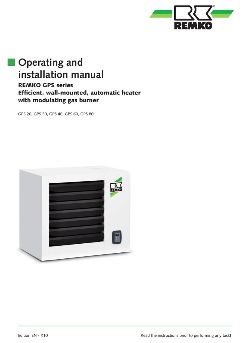
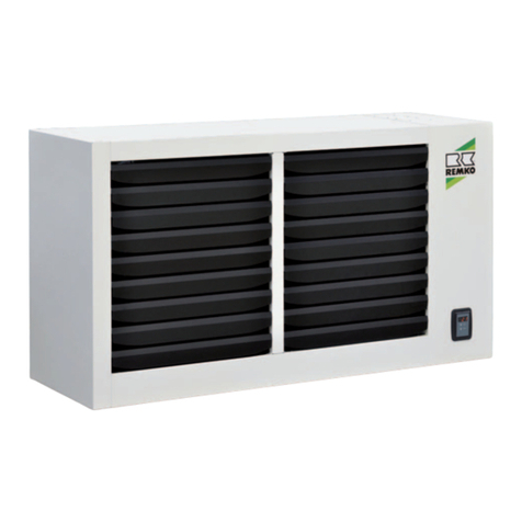
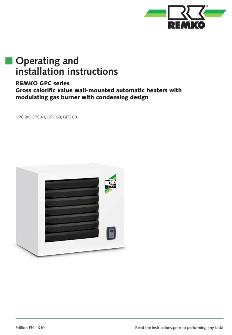
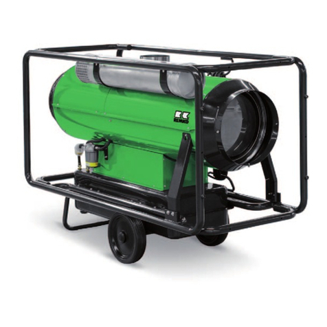
REMKO GPM Series User manual

Edition GB - W02
REMKO GPM
Gas wall heaters
Operation · Technology · Spare parts


3
Contents
Made by REMKO
Carefully read these operating instructions before commissioning/
using the units!
These instructions are part of the unit and must always kept near to
the site of installation or at the unit.
This operating manual is a translation of the German original, Version W-02
We reserve the right to make changes; no liability for errors and misprints!
Safety information 4
Installation of the unit 5
Description of the unit 6-11
Intended use 12
Customer service and warranty 12
Environmental protection and recycling 12
Control board parameter table 13
Temperature control ATR-6 14-19
Installation 20-22
Chimney connection 22-25
Electrical connection 26
Electrical wiring diagram 27
Gas connection 28
Commissioning 29-30
Maintenance 31-32
Replacing the control board 33
Chimney sweep button 33
Replacing the gas valve 34
Converting to LPG 35
Troubleshooting 36-37
Unit dimensions 38
Exploded drawing 39-40
Spare parts list 41
Table of countries and types of gas 42
Technical data 43

4
REMKO GPM
Safety information
The units were subjected to
extensive material, function and
quality inspections and tests prior
to delivery. However, the units
may constitute a hazard if used by
untrained personnel, improperly or
not for the intended purpose.
The following information must be
observed:
■
The units must only be
operated by persons who have
been instructed in the operation
of the units
■
In the event of faults that affect
safe operation of the units, they
must be switched off
■
The units must be installed and
operated so that the discharging
hot air has no damaging
effects on the environment or
equipment
■
Do not expose the units to the
effects of weather (rain, sun,
etc.)
■
Do not touch the units with
moist or wet parts of the body,
e.g. hands
■
Protect the units from splashing
water or other liquids
■
Do not use gas pipes for
grounding electrical equipment
■
Do not touch hot parts of the
units such as the chimney pipe
■
Do not moving parts of the units
The units must always be operated in compliance with the applicable
local building and fire protection regulations and regulations of the
employers‘ liability insurance associations.
■
Never insert foreign objects in
the units
■
The units must only be mounted
on constructions or ceilings
of flame retardant materials
designed to take the weight
■
The units must only be fastened
at the points provided at the
factory
■
The units must not be installed
and operated in locations
exposed to fire hazards
and potentially explosive
atmospheres
■
The units must be installed
outside traffic zones, e.g. of
cranes. A protective zone of 1 m
distance must be maintained
■
The air inlets including grilles
must be kept free of dirt and
loose objects at all times
■
The units must not be exposed
to a direct jet of water
■
The units must be tested at least
once a year by a specialist
■
Safety devices must not be
overridden or blocked!
■
Before carrying out
maintenance or repairs, the gas
supply must be shut-off and the
unit disconnected in all poles
from the mains supply.
(Unscrew fuse or switch off
local main/emergency switch)
Precautions if there is a smell
of gas
1. Immediately switch off the unit.
2. Close the gas shut-off valve(s).
3. Warn all persons potentially at
risk.
4. Open windows and doors.
5. Do not operate electrical
devices such as light switches or
electrical plug contacts.
6. If the room in which there is a
smell of gas cannot be entered,
immediately call the fire brigade,
police and if necessary the
responsible gas supply company.
The units are intended
exclusively for industrial and
commercial use. They are not
intended for domestic heating
or similar.
.
NOTE
ATTENTION
Installation, adjustments and
maintenance must only be
carried out by authorised
specialists.
The safety devices must not be
overridden or blocked during
operation.
ATTENTION

5
Installation of the unit
Area of application
REMKO GPM series gas wall
heaters are used for heating small
areas such as workshops up to
large areas such as industrial halls,
sports facilities, etc.
For economical heating, correct
calculation of the heat demand for
the required heat output for the
room is essential.
General preconditions
For installation of the units,
the local and country-specifi c
regulations and directives in the
latest version must generally be
observed.
The following work such as:
■
gas and electrical installation
■
change of gas type
■
commissioning
■
adjustment or maintenance
must only be carried out by
qualifi ed specialists.
In addition to perfect electrical gas
installation, this ensures that all
necessary measurements and tests
are also carried out.
■
The units must be tested at
least once a year by authorised
specialists.
The units can constitute a hazard
if not installed and operated
correctly. Prior to planning and
installation of the units, the
following must be observed
■
The units must be installed and
operated so that there is no risk
to persons due to exhaust fumes
and radiated heat and fi res
cannot occur
■
For installation of the units,
it must be ensured that the
discharging hot air has no
damaging effects on the
environment
■
Fire hazards must be prevented
depending on the materials of
the installation and mounting
surfaces. See TRGI, Section
5.1.3.3
■
Wall or ceilings intended for
mounting purposes must consist
of fl ame retardant materials.
Their load-bearing capacity must
be verifi ed, reinforcements must
be provided if necessary
■
Brackets must be securely
anchored to walls or ceilings and
the units fastened to the same
at the points provided at the
factory
■
Adequate maintenance options
for the heat exchanger, burner,
fan and chimney duct must be
provided
■
Operating devices for the unit
and fuel supply must be able to
be operated from ground level.
Maintenance and repair options
must be provided by the
operator
It is recommended to conclude
a maintenance agreement with
the specialised company for this
purpose
■
For planning and installation of
the chimney duct, the structural
possibilities and pertinent local
and country-specifi c regulations
must always be observed
■
In environments subject to
heavy fouling, cleaning and
maintenance must be carried
out depending on the respective
conditions.
In these cases, the combustion
air must always be supplied
from the outside
Selecting the site of
installation
For selecting the site of installation,
account must be taken of the
requirements with respect to:
■
Fire protection and operational
risk
■
Function:
Room heating, low pressure
and excess pressure in the
installation room, etc
■
Operating requirements,
heat demand, nominal air
volume fl ow, circulation air
requirements, humidity, room
temperature, air distribution,
space requirement
■
Mounting, repair and
maintenance options.
The units must be mounted so
that they are easily accessible
at all times for repairs and
maintenance
The units must not be installed
in rooms with an explosive or
corrosive atmosphere!
ATTENTION

6
REMKO GPM
Unit description
Unit definitions
According to EU directives, the
units are defined as:
“Gas hot air heaters without
draught diverters with a fan
upstream of the heat exchanger”.
The units are fully automatic,
direct-fired hot air heaters for wall
and ceiling mounting.
They can be fired with natural gas
or LPG.
The units are used for constant or
temporary heating of closed and
open rooms, e.g. in:
Halls, workshops, greenhouses,
storage rooms, etc.
Unit classification
The units are classified by the
European standards EN 437 and
EN 1020 according to:
Gas category:
Classification of the types of
gases with which the units can be
operated.
For Germany DE II2ELL3B/P
Type of gas:
The burner can be operated with
gases of the second family (natural
gas groups H and L) and with
gases of the third family (butane
and propane).
Type of gas appliance:
Classification according to options
for discharge of combustion
products and supply of combustion
air. (Room sealed/non-roomsealed)
For further information, see
chapter “Installation of chimney
duct and combustion air supply
pipe”.
Unit design
The outside housing of the units
is made of coated sheet steel for a
long useful life.
The outlet air grille(s) is/are
located at the front.
To ensure optimal hot air
distribution in the installation
room, the horizontal fins of the
air outlet grille can be adjusted
manually.
The circulation air fan(s) with
outlet grille, exhaust fume
discharge and combustion
air supply connections, gas
connections, electric cable lead-
throughs and plug connector for
mains connection are located at
the rear of the unit. Located on the
right side behind the inspection
door are the components
necessary for control and safety
such as
- the electrical circuit with wiring
- the control electronics
- the gas valve
- the modulating gas burner
The combustion chamber with
heat exchanger is located inside
the unit, directly in the circulation
air flow.
The combustion chamber is made
completely of Inox stainless steel
AISI 430.
Inox stainless steel AISI 441 is used
for the heat exchanger for higher
resistance to corrosion due to
moist vapours.
The special shape and large surface
of the combustion chamber and
heat exchanger ensure high
efficiency and a long service life.
The gas burner is also made
completely of specially machined
stainless steel.
Function of the units
GPM series modulating gas
wall heaters were developed for
heating rooms in industrial and
commercial premises.
The electronic control of the units
continuously regulates the heat
output between minimum and
maximum depending on the actual
heat demand.
Efficiencies of up to 94% can be
achieved with the premixing and
modulating technology.
The nominal heat output of the
REMKO GPM series is between
11.8 and 71.5 kW.
They essentially consist of the
combustion chamber with heat
exchanger and circulation air
fan(s).
The ambient air is sucked in by
the fan(s) and flows efficiently
via the burner chamber with heat
exchanger.
The combustion chamber is heated
by the gas burner and heats the
passing flow of air.
The air heated in this way is blown
out the front of the unit via an
adjustable air outlet grille.
Correct operation of the unit is
only possible with a connected
temperature control, e.g. ATR-6
(accessory).
The units are not suitable for
domestic heating or similar.
NOTE

7
■
Operation of the safety
thermostat and associated
interlock of the safety
thermostat (STB).
The unit cannot be restarted
without manual reset
■
Damage to electric cables
Safety thermostat(s)
Each fan in the units has a safety
thermostat (STB) for manual reset.
Operation of the safety thermostat
triggers a safety shutdown.
The thermostat is arranged in
the area of the heat exchanger in
order to monitor the temperature
at its outlet.
Blocking of the unit caused by
operation of the safety thermostat
is indicated as fault F2 at the
temperature control.
Air/gas premixture
The units are provided with a
burner with complete air/gas
premixture.
Mixture takes place in the burner
motor fan.
The air sucked in by the fan fl ows
through the Venturi tube, where a
vacuum is produced, which draws
the gas.
This produces a constant air/gas
mixture. The ratio of air and gas
pressure is 1:1.
This value can be changed with
the offset regulating screw located
on the gas valve.
The gas volume is already adjusted
on delivery of the units and the
screw is sealed.
Fine adjustment can be made
with the adjusting screw on the
Venturi tube. This screw regulates
the maximum gas fl ow rate and
accordingly determines the carbon
dioxide (CO2) content of the
exhaust gases.
The screw is not sealed so as to
allow the hot air heater to be
changed to a different type of gas
if necessary.
NOTE:
For offset and CO2 adjustment.
The control board of the units
controls the burner motor speed
with DC current depending on the
room heat demand.
The air and accordingly the gas
fl ow rate changes with changing
speed.
The minimum and maximum fan
speeds are two values that cannot
be changed.
Fans
The circulation air fans are
switched on by the control board
time-controlled, whereby time
control starts when the main
burner is switched on.
The delayed switch on prevents
cold air from being blown into the
room.
Switching off the unit
If there is no more heat demand
(room temperature above the set
value), the control board switches
off the burner.
The burner fan continues to run
for a preset time in order to cool
the combustion chamber.
The circulation air fan (possibly
also more than one) also continues
to run time-controlled until the
heat exchanger has cooled down.
If there is a renewed heat demand
during the after-running phase,
the control board will wait for the
fans to switch off and only then
perform a reset and begin with a
new cycle.
IMPORTANT INFORMATION!
Interrupting the power supply
during burner operation or the
residual heat removal phase must
be avoided as a lack of cooling of
the heat exchanger can lead to
considerable damage.
■
Overheating of the unit with
invalidation of the warranty
■
Damage to the burner fan and
its components
ATTENTION
Before resetting a safety
device, the cause of its
operation must be located and
eliminated.
NOTE
Safety devices must not be
overridden or blocked during
operation of the unit.

8
REMKO GPM
The units offer the benefit of a
modulating mode of operation,
i.e. the produced heat output and
accordingly the gas flow rate (fuel
consumption) vary depending on
the heat demand.
With a reduced room heat
demand, the hot air heater
consumes less fuel, whereby its
efficiency is increased up to 94%.
Intrinsic safety
An increase in efficiency at
minimum output is achieved by
the use of a modern air/gas mixing
technology and simultaneous
regulation of the combustion air
and gas flow rate.
This technology increases the
safety of the unit as the gas valve
supplies the fuel depending on
the air flow rate according to its
factory setting.
In contrast to an atmospheric
burner, the CO2 content remains
the same over the entire control
range of the units and allows
an increase in efficiency with a
reduced heat output.
If there is no combustion air, the
valve does not release any gas.
With a reduction of combustion
air, the gas valve automatically
reduces the gas volume and keeps
the combustion parameters at an
optimal level.
Minimal pollutant emissions
The premixing burner allows in
conjunction with the air/gas valve
“clean” combustion with very low
pollutant emissions.
EfficiencyOperating cycle
Burner operation
The heat demand for starting the
burner takes place via the set value
of the room temperature sensor in
the temperature control ATR-6.
For units both with and without
temperature control, the burner is
only started when the contact 7+9
on the terminal strip M1 is closed.
On receiving a heat demand,
the control board first starts the
burner fan so that the combustion
chamber is pre-aerated for a
certain time.
After pre-aeration, the control
board activates the flame
monitoring device ACF for igniting
the burner by energising the gas
solenoid valve EV1 and EVP, which
supplies the ignition gas burner.
In this way, the gas burner is
started.
The ignition monitoring electrode
monitors correct ignition of the
ignition gas burner.
When this operating condition is
detected, the control device of
the main gas valve EV2 opens to
supply the actual main gas burner.
After a certain time, while both
burners (ignition and main gas
burners) are operating at the
same time, the control board de-
energises the solenoid valve EVP,
whereupon the ignition burner
extinguishes.
Flame monitoring for supervision
of the main gas burner is
continued by the monitoring
electrode.
The start program switches on the
main gas burner with an average
heat throughput of about 70%.
After about 30 seconds, the
burner starts to modulate the gas
flow rate and finally reaches the
adjusted gas flow rate.
During operation, the control
board regulates the gas flow rate
of the burner proportional to the
circulation air temperature, which
is measured by the NTC1 sensor at
the rear of the unit.
Luft
Abgase
Gas
EV1EV2
EVP
HW080909
Exhaust gases
Air
Gas

9
Modulation
The gas wall heaters are units
with gas burner modulation which
makes operation with diverse
outputs between minimum and
maximum possible. The maximum
output serves to quickly raise the
room temperature when the units
are switched on.
With the modulation feature
by contrast, the required room
temperature can be maintained
at a constant level with constant
variation of the heat output
appropriate to actual demand.
With this automatic adjustment
of the heat output to the
room conditions, the physical
phenomena of layer formation (the
tendency of heat to rise) can be
restricted due to the reduction of
the air supply temperature.
The temperature differences per
metre are below 0.5°C.
When the units operate with a low
heat output, effi ciency above 94%
is achieved.
These results can only be achieved
by precise monitoring of the
climatic room conditions and
optimal control of the units.
For dimensioning heating centres
with hot air heaters, it is important
to observe the number of hourly
air exchanges.
In this respect, the following
should be noted:
Wall gas heaters should generally
be dimensioned so that the air
fl ow rate ensures a minimum of
two air exchanges per hour, even
if this is unnecessary for the heat
output.
The units have a room temperature
sensor NTC1 located at the rear
of the unit as standard so that
the temperature of the air sucked
in by the circulation air fans is
monitored.
Modulation takes place depending
on the value measured by this
sensor in a ratio to the value preset
on the microprocessor on the
control board.
Optimisation of the modulation
temperature value must take place
during operation of the system and
depends on the distance of the hot
air heater from the ground and
required temperature conditions.
The wall gas heater is normally
installed at a distance of 2.5 to 4 m
from the ground.
This ensures that the required
comfort temperature is reached
and maintained, whereby it is
important that the units are
operated at the lowest possible
modulation temperature which
is necessary to maintain these
conditions.
The modulation temperature (REG
SAN value) is factory set at 21°C.
This value allows an average
installation range between 3 and
5 metres at room temperatures
between 17 and 19°C
(see graph below).
Nominal
value at a
height of
1.5 m
Unit installation
height in metres
2.5 3 4 5
15° 16° 17° 18° 19°
16° 17° 18° 19° 20°
17° 18° 19° 20° 21°
18° 19° 20° 21° 22°
19° 20° 21° 22° 23°
20° 21° 22° 23° 24°
Kurve 1:1
korrigierte Kurve
Luftdruck (-durchsatz)
Gasdruck (-durchsatz)
90
91
92
93
94
95
96
65 70 75 80 85 90 95 100
Wärmedurchsatz [%]
Wirkungsgrad %
18
20
22
24
26
28
Wirkungsgrad
D Luft
t
D Zuluft
t
ATTENTION
Unit parameters can only be changed in conjunction with the elec-
tronic temperature control ATR-6.
The above diagram shows the effi ciency
and temperature difference of the air
supply with a reduction of the heat
throughput.
Effi ciency
Supply air
Gas pressure (fl ow rate)
Corrected curve
Curve 1:1
Air pressure (fl ow rate)
Air
Heat throughput [%]
Effi ciency %

10
REMKO GPM
Room correction
For this function, use of the
temperature control ATR.6 is
necessary.
A type of function is described
in the following that enables
maximum energy efficiency to
be achieved by the hot air heater
assisted by the control electronics
and temperature control.
In order to activate the ambient
correction function, the parameter
[C1] param k 11 must be set to 1.
The purpose of the room
correction function is to ensure
rapid heating at the beginning and
subsequently maintain the room
temperature at a constant level.
In this way, not only can layer
formation in the room air be
reduced, but also the fuel demand
reduced in particular.
The two correction reference
values are the temperature
measured by the sensor NTC2
(in the temperature control) and
the circulation air temperature
measured by the sensor NTC1 (at
the unit).
To activate the function, set the
parameter param k 17 to 1.
When the room temperature
approaches the setpoint value,
the modulation temperature is
changed linearly based on the two
parameters A16 and A24.
This makes it possible to operate
the unit on heat demand
at maximum output and to
quickly reach the preset room
temperature.
The heat output is subsequently
reduced which increases the
efficiency of the unit and the room
is heated with less hot air.
This enables the layer formation in
the room air and simultaneously
the heat loss to be reduced.
The units are supplied with the
following factory settings:
Modulation temperature:
„REG SAN“ 22°C
Neutral correction range:
A24 2°C
Correction coefficient:
A16 2
The parameter A24 determines
the range within which the
room temperature is corrected.
The parameter A16 offers the
possibility to increase the efficiency
of the temperature reduction
to the setpoint “REG SAN” as
shown on the graph. At the
standard setting, the modulation
temperature on reaching the room
temperature corresponds to:
„REG SAN“ =
24°C-(2°C x 2.5) = 19°C
The correction is independent of
the set room temperature.
The graph shows the room
temperatures [ST2] in relation
to the installation height of the
units „REG SAN“ during the initial
heating phase.
To deactivate the correction, set
the parameter [C1] param k 11 to
0.
When deactivating the correction,
the value “REG SAN” must be
correctly regulated in order to
avoid the following conditions:
- „REG SAN“ adjusted too high:
Strong layer formation with
high heat loss in roof area and
increased energy demand as a
consequence.
-
„REG SAN“ adjusted too low:
Time to reach the required room
temperature too long.
With correction deactivated, adjust
“REG SAN” so that the value is
higher than ST2 by the difference
in metres between the room and
modulation sensor multiplied by
0.4/0.5°C.
To change the modulation value
“REG SAN” on the temperature
control and to change all specified
values, see further back in the
manual.
Raumtemperatur
Modulationstemperatur
ST1
ST2
A24
A24 x A16
ST1 Korrektur
ST1
ST2
0,5h 1h 1,5h 2h 2,5h 3h
Modulation temperature
Room temperature
ST1 correction

11
The faults indicated and stored by
the control board (interlocks) have
the following causes:
F1
- Fault of the fl ame monitoring
device due to burner ignition
failure; the control board
makes several automatic reset
attempts prior to signalling
the fault.
F2
- Operation of the safety
thermostat.
If the temperature detected
by the thermostat is too high,
the same operates and blocks
operation of the unit.
F3
- Burner fan faulty; the
combustion air fan is faulty or
the signal to the control board
is outside the tolerance range
with respect to the requested
speed.
F4
- NTC1 sensor faulty or not
connected – the sensor value
is outside the measuring
range.
F6
- Control board fault due
to constant and repeated
unsuccessful ignition attempts
of the unit for a predefi ned
period.
With this fault, the fault
signalling LED located on the
control board also lights up.
F8
- The control board sent the
starting signal to the fl ame
monitoring device, but did
not receive the started signal;
it is possible that the fl ame
monitoring device is faulty.
The faults F1 and F2 are caused by
safety devices and are therefore
permanent.
The fault still remains after
switching the mains off and
on again and can only be reset
manually.
The faults F3, F6 and F8 must be
reset manually or by switching the
mains off and on again.
In contrast, fault F4 is self-
resetting:
After clearing the fault, reset takes
place automatically.
The safety information on the
previous pages must be strictly
observed.
In exceptional circumstances, the
units can also be operated briefl y
without temperature control.
For this purpose, the jumper on
terminals 7+9 on the terminal
strip M1 in the switchbox must be
removed and a switching device
(e.g. thermostat) connected.
The CR switch on the control
board must be set to OFF (see Fig.
on page 14) and the connector CN
with resistor (see Fig. on page 26)
plugged in.
For this mode, it is neces-
sary to connect at least one
switching device, e.g. room
thermostat in order to be able
to switch the burner on and
off.
NOTE
All information relating to the unit
and faults are now indicated via
LED indicators on the front of the
unit.
The green LED lights up to indicate
that the unit is connected to the
mains.
The red LED lights up to indicate a
fault on the unit.
The cause of the fault can
immediately be identifi ed by the
different fl ashing/illuminating
states of the red LED:
F1
- LED shows a steady light
F2
- LED fl ashes twice rapidly
F3
- LED fl ashes three times
rapidly
F4
- LED fl ashes four times rapidly
F8
- LED fl ashes constantly
F6
- Red and green LED fl ash
alternately
General information Types of faults
Reset button
A manually operated reset button
on the front of the unit enables
the unit to be reset following faults
F1, F2 or F8 when the temperature
control ATR-6 is not present.
d
Z
Changeover switch
Summer / d Winter
Reset button Green LED
Red LED
Summer/winter switch
A manually operated changeover
switch d / 0 / on the front
of the unit allows switching
from winter operation d to
summer operation (continuous
ventilation).
In the middle position [0], all
functions of the unit are switched
off.

12
REMKO GPM
Due to their design and
equipment, the units are
intended solely for heating and
ventilation purposes in industrial or
commercial use (not for domestic
heating).
The design of the unit allows the
use of accessories approved by the
manufacturer.
The appliances must only be
operated by suitably trained
personnel.
The manufacturer disclaims all
liability for any damage attributed
to failure to observe relevant
instructions, statutory requirements
applicable at the place of use or
unauthorised changes to the unit.
Improper use of the units is not
permitted.
The units must be installed
by a qualified installer who is
responsible for adhering to the
existing rules, regulations and
directives.
Customer service and
warranty
A precondition for any warranty
claims is that the dealer or his
customer has completed and
returned the enclosed “warranty
document” to REMKO GmbH &
Co. KG.
The units were repeatedly tested
for perfect functioning at the
factory.
If problems should occur
which cannot be remedied by
troubleshooting by the operator,
your specialised dealer or contract
partner should be contacted.
Intended use
Disposal of packing
When disposing of the packaging
material, please think of the
environment.
Our units are carefully packed for
transport and delivered in sturdy
cardboard packaging on a wooden
pallet, if necessary.
The packaging materials are
environmentally-friendly and can
be recycled.
By reusing packaging materials,
you make a valuable contribution
towards waste reduction and the
conservation of raw materials.
Only dispose of packaging
material at the facilities provided.
Disposal of old unit
Our production is subject to
constant quality controls.
Only high-quality materials are
used, the majority of which are
recyclable.
Make your contribution towards
environmental protection by
disposing of your old unit in an
environmentally-friendly manner.
Only dispose of your old unit at
an authorised recycling facility or
similar.
Environmental
protection and
recycling
Improper use of the units is
not permitted.
The units must be installed
by a qualified installer who is
responsible for adhering to the
existing rules, regulations and
directives.
NOTE
Adjustments and maintenance
must only be carried out by
authorised specialists.
NOTE
ATTENTION
Copyright
No part of this
documentation may be
reproduced or used for any
other purposes than the
intended without the express
prior written permission of
REMKO GmbH & Co. KG.

13
param k TSP GPM 15 GPM 25 GPM 35 GPM 55 GPM 75
1 A1 44 55 62 65 75
2 A2 58 73 93 93 98
3 A3 83 83 80 70 70
4 A4 5
5 A5 10
6 A11 25
7 A17 4
8 A28 50
9 A34 10
10 A35 0
11 C1 0
12 C3 60
13 C4 120
14 C5 0
15 C8 0
16 ST3 5
17 A12 0
18 A16 2
19 A24 2
20 A15 0
21 A31 2
22 A43 0
23 A44 0
GPM control board parameter table
The values in the aforementioned table are factory default settings
K4
K3K2
K1
KM
K-
K+
Info Reg err
Press the K4 (>>) button, the
following text display appears.
K4
K3K2
K1
KM
K-
K+
spra par park
Press the K3 park button; the
text line param k 1. appears in the
following display.
The parameters param k 1 to 3 can
be selected with the K4 (>>)
up button, or K1 down button
(<<).
The respective values displayed
at the top can be changed as
appropriate with the K+ or K-
button.
Press and hold the KM button for
10 seconds to return to the basic
display.
K4
K3K2
K1
KM
K-
K+
param k 1
62
Adjusting parameter values
Press and hold the KM button
for about 10 seconds until the
following display appears.
ATTENTION
All unit parameters can only
be changed in conjunction
with the electronic
temperature control ATR-6.
ATTENTION
Changes to parameters may
only be made as described in
these operating instructions
and approved.
Where customer-specifi c
parameter changes are made,
these must be documented in the
aforementioned table.
In the event of control board
replacement, the values must be
reprogrammed.
See also (page 33) „Control board
replacement“.
Parameters can only be
adjusted when the unit is not
in operation.
NOTE

14
REMKO GPM
Resetting
The fault (interlock) is indicated by
the red LED on the unit lighting
up, a triangle flashing on the
temperature control display and
the fault code “Reset heating”
being displayed.
For fault code analysis and
resetting, see chapter “Fault
message display” (page 18) and
“Type of faults” (pages 11 + 37).
A reset must only be
performed 20 seconds after
switching off the unit.
ATTENTION
The changeover switch at
the front of the unit with
temperature control ATR-6
must always be set to winter
operation d.
NOTE
The temperature control ATR-6
can display possible system faults
and supply diagnostic information.
Display:
The display is completely blank.
Meaning:
The buffer capacitor is discharged
as it was without charge for more
than 5 hours.
Restore the power supply and wait
until the display lights up.
The time, day and required
room temperatures must be
reprogrammed.
The buffer capacitor is fully
charged within about 1 hour.
All parameters necessary for
operation of the unit are stored
indefinitely on the control board.
Only the day and time as well as
the required on and off program
need to be reprogrammed.
The temperature control requires
no particular maintenance.
The temperature control ATR-6
is microprocessor-controlled and
intended for convenient room
temperature control as well as for
diverse unit settings and status
displays.
Features:
■
week program with timer
■
3 different temperature settings
per day possible, T1, T2 and T3
■
temporary cancellation of the
set temperature
■
automatic and manual mode,
timer program
■
frost protection mode 5°C
permanently in OFF state
■
automatic output control
according to heat demand
■
current status display
■
display of faults or malfunctions
■
remote reset button
■
operation without batteries
■
power reserve 5 hours
■
non-polarised two-wire
connection
Checking the board hardware
configuration
The jumper NTC/VAN must be
located on NTC and the CR switch
must be set to ON (towards the
inner part of the board), see
diagram below.
This configuration is necessary to
ensure the correct function of the
NTC1 sensor.
Jumper NTC
CR switch
ON
NOTE
All unit parameters can only
be changed in conjunction
with the electronic
temperature control ATR-6.
Temperature control ATR-6

15
Do not use any pointed
objects such as ball-point
pens or pencils for pressing
the buttons as these can be
damaged.
ATTENTION
4 6 8 10 12 14 16 18 20 22 24 2
°C
AM
PM
!
K+ button
K– button
KM button
K3 button
K1 button
Room
temperature
Text bar
K4 button
K2 button
Day,
Hour,
Minutes
Error display
Ventilation mode Manual mode
Heat demand
Heating mode Switch off mode Timer
programming
LCD display
The temperature control ATR-6 uses an alphanumeric LCD display, as
shown below.
There is a choice of three
languages: German, English and
French.
Press the K1 button and select the
required language with the K+ and
K- buttons.
Confi rm the language selection
with the K4 OK button.
Press and hold the KM button for
10 seconds to return to the basic
display.
K4
K3K2
K1
KM
K-
K+
tag std min
16:00
mo
Set clock
Press the KM button, HZG appears
on the left in the bottom text bar.
Press the K4 (>>) button, the
following display appears.
Set the language
Starting display with initial use.
K+
K-
KM
K1 K2 K3 K4
4 6 8 10 12 14 16 18 20 22 24 2
09:38mo 20,0
Press the KM button once briefl y
(only for initial use).
Press and hold the KM button for
about 10 seconds until the text
display in the bottom text bar
changes from Chau to Info.
K4
K3K2
K1
KM
K-
K+
chau heur min
16:o2lu
K4
K3K2
K1
KM
K-
K+
Info Reg err
Press the K4 (>>) button to change
from display Info to „Lang“ (Lan-
guage).
K4
K3K2
K1
KM
K-
K+
lang par parc
With K3 select Uhr and the
following display appears.
K4
K3K2
K1
KM
K-
K+
prog reg uhr
With the K1, K2 and K3 buttons,
select the week day, hour and
minutes.
The current selection is indicated
by fl ashing.
The K+ and K- buttons increase
and decrease the displayed
parameter value.
Press the KM button to exit the
level.

16
REMKO GPM
Automatic mode
In this program, the temperature
control controls the wall gas heater
fully automatically.
The room temperature, week day
and current time in hours and
minutes are indicated permanently
on the LCD display.
Program example:
Programming a day temperature
(T3) of 20.5°C Monday to Friday
from 700 - 1700 .
Programming a medium
temperature of 18°C lunch time
from 1200 - 1400.
Programming a night temperature
(reduction temperature) of 15°C
from 1700 - 700.
Programming a continuous night
temperature (T1) of 15°C from
Saturday to Sunday.
Settings can be programmed as
follows:
Press the KM button, HZG appears
on the left in the text bar.
K4
K3K2
K1
KM
K-
K+
prog reg uhr
K4
K3K2
K1
KM
K-
K+
prog reg uhr
Make a selection with the K1 prog
button. The following display
appears.
K4
K3K2
K1
KM
K-
K+
tag reg cop vor
4 6 8 10 12 14 16 18 20 22 24 2
13:00mo
Press the K1 tag button
repeatedly to select the week day
(e.g. Monday).
Make a selection with the K2 reg
button, the temperature windows
T1 and T3 appear.
K4
K3K2
K1
KM
K-
K+
t1 t2 t3
..
Press the K4 button (>>), the
following display appears.
Existing settings must always
first be deleted on
Level
T1 with
the
K+
and
K-
buttons.
Position the cursor on the
clock from where the program
is to be started on the next
temperature window (e.g. 700).
No corrections (overwrite) can
be made on levels T2 and T3.
ATTENTION
Press the K2 reg button, the
following display with the
temperature window T3 appears.
K4
K3K2
K1
KM
K-
K+
tem raum t1
10,0
REG SAN Value
By pressing the K4 (>>) button
twice again (after the temperature
window 3), the Reg san display
appears.
Adjust the flashing temperature
indication appropriate to the unit
installation with the K+ and K-
buttons.
See the table under the section
“Modulation” (page 9) in these
operating instructions.
Programming can be ended by
pressing the KM button.
The temperature control has 3
temperature windows.
T1 = Reduction temperature
(night)
T2 = Medium temperature
T3 = Day temperature
The procedure for setting and
changing is as follows:
Press the KM button, HZG appears
on the left in the text bar.
Press the K4 (>>) button, the
following display appears.
With the K+ and K- buttons select
the required temperature (e.g.
15°C) for the temperature window
T1.
Press the K4 (>>) button to display
the temperature window T2.
With the K+ and K- buttons set
the required temperature (e.g.
18°C) for T2.
Press the K4 (>>) button to display
the temperature window T3. With
the K+ and K- set the required
temperature (e.g. 20.5°C) for T3.
Setting temperature window and REG SAN value

17
Further week days can now
be programmed individually as
previously described or by copying.
The procedure for copying is as
follows:
Copy the already programmed day
with the K3 cop button and press
the K1 tag button.
Press the K3 cop button and the
K1 tag button again.
Repeat this procedure for each
further week day with the same
data.
NOTE
All times indicated without
bars run automatically in the
night temperature zone t1.
Continuous mode
In this mode, the control operates
continuously at a set room
temperature.
Settings can be programmed as
follows:
Press the KM button, HZG appears
on the left in the text bar.
K4
K3K2
K1
KM
K-
K+
HZG san info
K4
K3K2
K1
KM
K-
K+
auto on off uhr
Press the K1 hzg button, the
following display appears.
Press the K2 ON button, the
following display appears.
K4
K3K2
K1
KM
K-
K+
temperatur man
24,0
K4
K3K2
K1
KM
K-
K+
temperatur man
24,0
Set the fl ashing temperature indi-
cation to the required value with
the K+ and K- buttons.
By pressing the KM button, the
mode is permanently activated.
The basic display now appears
without timer bar.
K+
K-
KM
K1 K2 K3 K4
4 6 8 10 12 14 16 18 20 22 24 2
09:50di 25,0
Manual mode
While the temperature control is in
the automatic mode, the required
room temperature can be changed
at any time by pressing the K+ or
K- buttons.
Press the K+ or K- button, the
following display appears.
Set the fl ashing temperature
indication to the required value
with the K+ and K- buttons.
By pressing the KM button, the
mode is activated and indicated on
the display with a hand symbol.
This setting is automatically ended
again at the next programmed
switching point.
Press the K4 t3 button and with
the K+ button set the fl ashing
cursor in the top bar from the
position 700 to 1200.
In the position from 700 - 1200 a
full bar is displayed.
Exit the temperature level t3 with
the K2 reg button.
Press the K3 t2 button and with
the K+ button move the fl ashing
cursor from 1200 - 1400.
In the position from 1200 - 1400
half a bar is displayed.
Exit the temperature level t2 with
the K2 reg button.
Press the K4 t3 button and with
the K+ button set the fl ashing
cursor in the top bar to the
position 1700.
In the position from 1400 - 1700
a full bar is displayed. Exit the
temperature level t3 with the K2
reg button.
K4
K3K2
K1
KM
K-
K+
tag reg cop vor
4 6 8 10 12 14 16 18 20 22 24 2
13:00mo
NOTE
The automatic mode can
be selected prematurely by
pressing the
KM
button, the
K1
hzg button and the
K1
auto
button.
NOTE
The automatic mode can be
reselected by pressing the
KM
,
button, the
K1
hzg button and
the
K1
auto button.

18
REMKO GPM
K4
K3K2
K1
KM
K-
K+
HZG san info
Press the K1 hzg button, the
following display appears.
Timer mode
In this mode, the temperature con-
trol operates within a fixed time
window.
Press the KM button, HZG appears
on the left in the text bar.
Press the K1 HZG button and in the
following display press the K4 uhr
button.
In the following display, set the
flashing time/hour indication to
the required value with the K+ or
K- button.
K4
K3K2
K1
KM
K-
K+
timer
4 6 8 10 12 14 16 18 20 22 24 2
17:00fr 24,0
The timer mode is indicated in the
display with timer.
The timer can be set up to 12
hours in 30 minute steps.
After lapse of the timer program-
med time, the unit switches back
to the automatic mode again.
K4
K3K2
K1
KM
K-
K+
dauer temp
20,0
02:00
Press the K4 temp button and set
the flashing temperature indication
to the required value with the K+
or K- button.
Press the KM button to return to
the operational display.
Fault message display
The temperature control ATR-6
can display possible system faults
and supply diagnostic information.
Possible Unit faults are indicated
by a flashing triangle and ”Reset
heating” in the following display.
!
K4
K3K2
K1
KM
K-
K+
reset
4 6 8 10 12 14 16 18 20 22 24 2
08:25di 18,5
kessel
!
K4
K3K2
K1
KM
K-
K+
fehlercode
!1
Faulty code analysis is described in
the chapter “Troubleshooting” in
the operating instructions.
By pressing the K4 (>>) button,
the fault code (e.g. 1) is displayed.
NOTE
After 5 unsuccessful reset att-
empts, the control electronics
of the unit are permanently
locked.
In order to restart the unit, it
must be disconnected from the
mains supply.
NOTE
The timer program can be
ended prematurely by pressing
the
KM
button, the
K1
hzg but-
ton and the
K1
auto button.
NOTE
The heating program can be
reactivated by pressing the
KM
button, the
K1
hzg button and
the
K1
auto button.
Prior to troubleshooting and
clearing faults, no reset must be
performed.
ATTENTION
K4
K3K2
K1
KM
K-
K+
auto on off uhr
Switch off the unit
Press the KM button, HZG appears
in the text bar.
K4
K3K2
K1
KM
K-
K+
13:50fr 20,0
NOTE
In this mode, frost protection
is automatically activated at a
temperature of 5°C.
Press the K3 off button, the fol-
lowing display and symbol appear.
After locating and clearing the
fault, the unit must be reset via the
K1 reset button.

19
ATTENTION
In a heating mode, parameter
10 must be reset to the value 0.
Summer mode (only
ventilation)
In the summer months, ventilation
can also take place via the
temperature control ATR-6.
However, this function must
initially be activated on the control
board.
Setting parameter value
Press and hold the KM button
for about 10 seconds until the
following display appears.
K4
K3K2
K1
KM
K-
K+
Info Reg err
Press the K4 (>>) button to access
the following display.
Press the K4 (>>) button to access
the following display.
K4
K3K2
K1
KM
K-
K+
spra par park
Press the K3 park button and in
the following display press the
K4 (>>) button several times until
param k 10 appears.
With the K+ or K- button, set the
value to 1.
Press and hold the KM button for
10 seconds to return to the basic
display again.
K4
K3K2
K1
KM
K-
K+
param k 10
1
Setting the PROG SAN value
To set the ventilation function, the
prog san value must be set to the
appropriate mode.
The procedure is as follows:
Press the KM button, the following
display appears.
K4
K3K2
K1
KM
K-
K+
HZG san info
K4
K3K2
K1
KM
K-
K+
HZG san info
Activating/deactivating
ventilation
Press the KM button, the following
display appears.
K4
K3K2
K1
KM
K-
K+
prog reg uhr
Press the K4 (>>) button several
times until prog san appears.
With the K+ or K- button, set the
value to 1.
Press the K2 reg button to access
the following display.
K4
K3K2
K1
KM
K-
K+
tem raum t1
10,0
K4
K3K2
K1
KM
K-
K+
prog san
1
This operation can be ended by
pressing the KM button.
K4
K3K2
K1
KM
K-
K+
on off uhr
The ventilation function can be
activated with the K2 on button
or deactivated with the K3 off
button.
Ventilation mode on is indicated
on the display with a water tap
symbol.
Ventilation can be programmed
for a fi xed time with the K4 uhr
button.
The timer can be set up to 12
hours in 30 minute steps.
A water tap symbol and timer are
indicated on the display.
NOTE
The timer program can be
ended prematurely by pressing
the
KM
button, the
K2
san
button and the
K3
off button.
By pressing the K2 san button, the
following display appears.

20
REMKO GPM
The following instructions for
installation adjustment of the
units are intended exclusively for
authorised specialists.
The following safety information
must be observed.
General information
The units can normally be installed
directly in the room to be heated.
Installation of the units must
always take place in compliance
with the building regulations
(LBO) and the Ordinance on
Firing Installations (FeuVO) of the
respective federal state.
The First Ordinance on the
implementation of the Federal
Immission Control Act (1st
BImSchG) and the subsequently
issued statutory requirements of
the Ordinance on Small Firing
Installations (1st BImSchV) must
also be taken into account.
The installation of hot air heaters
operating with gas burners is
forbidden in the following rooms:
■
in public functional rooms or
in rooms with a person density
from 0.4 per square metre
■
in rooms in which gas or dust
can form due to the processes
occurring in these rooms or
through materials stored in
these rooms
Installation instructions
The minimum height and distances
of the hot air heater from walls
and floors are shown in the dia-
gram below.
The minimum distances are the di-
stances necessary for maintenance.
All dimensions are in mm. The
height [2500 mm] corresponds
to the minimum height for “sus-
pended units” as specified in the
applicable directives.
Two different types of brackets are
available as accessories for instal-
lation.
Fixed and hinged.
The order numbers for the wall
bracket (hinged type) are:
EDP No: 228761; GPM 15/35
EDP No: 228762; GPM 55
EDP No: 228762; GPM 75
200 1000
4002500
To avoid dangerously high
voltages be reached, the distance
between the outer surface of
the unit and chimney pipe and
any possibly stored flammable
material at a distance to the floor
of 2.5 m or above must under no
circumstances be below 1.5 m.
Units with gas burner for gas
with a density above 0.8 (LPG,
propane, butane) may only be
installed in rooms in which the
floor is not below ground level.
Ventilation openings
Rooms in which gas-operated units
are used must have one or several
permanent openings (windows or
doors).
These openings must be provided
at the following points:
- directly below the ceiling for
gases with a density below 0.8;
- directly above the floor for
gases with a density above or
equal to 0.8.
Openings in outside walls must be
provided externally. The installed
heat output is decisive for the
cross-sectional sizes.
Installation
We reserve the right to make changes to dimensions and design in the interest of technological advances.
Other manuals for GPM Series
1
This manual suits for next models
5
Table of contents
Other REMKO Heater manuals

REMKO
REMKO EST User manual

REMKO
REMKO GPS 20 Specification sheet
REMKO
REMKO DZH Series User manual

REMKO
REMKO CLA 50 User manual

REMKO
REMKO HTL 150-FB User manual

REMKO
REMKO ELKOMAT 6 User manual

REMKO
REMKO HTL 250-EC User manual

REMKO
REMKO PGM 30 User manual
REMKO
REMKO CLK170-RV User manual
REMKO
REMKO PWW 5000 Series User manual
Popular Heater manuals by other brands

Frico
Frico AREC3200CA Original instructions

EdenPURE
EdenPURE Signature Operation and warranty manual

Remington
Remington REM22CEH owner's manual

Alutherm heating
Alutherm heating A 170 Installation, user and service manual

EOS
EOS THERMAT Installation and operation instruction

Sunshower
Sunshower PURE XL installation guide