S+S Regeltechnik THERMASREG FS Repair manual

THERMASREG® FS
D G F r
Herzlichen Glückwunsch!
Sie haben ein deutsches Qualitätsprodukt erworben.
Congratulations!
You have bought a German quality product.
Félicitations!
Vous avez fait l’acquisition d’un produit allemand de qualité.
Примите наши поздравления!
Вы приобрели качественный продукт, изготовленный в Германии.
D
Bedienungs- und Montageanleitung
Frostschutzthermostat,
mit aktivem und schaltendem Ausgang
G
Operating Instructions, Mounting & Installation
Frost protection thermostat,
with active and switching output
F
Notice d’instruction
Thermostat antigel à capillaire
à sortie active et en tout ou rien
r
Руководство по монтажу и обслуживанию
Термостат защиты от замерзания,
с активным и релейным выходом
FS
mit Display
with display
avec écran
с дисплеем
FS
6002-0400-2011-000 20400-2014 01 ⁄ 2014
S+S REGELTECHNIK GMBH
PIRNAER STRASSE 20
90411 NÜRNBERG ⁄GERMANY
FON +49 (0) 911 ⁄ 519 47-0
FAX +49 (0) 911 ⁄ 519 47-70
www.SplusS.de
1 2
# 14-4141 (wie Katalog-2014, ab Seite 154)1. KORREKTUR | 21. 01. 2014 ⁄ PR # 20400 - 2014

THERMASREG® FS
D G F r
Maßzeichnung
Dimensional drawing
Plan coté
Габаритный чертеж
Herzlichen Glückwunsch!
Sie haben ein deutsches Qualitätsprodukt erworben.
Congratulations!
You have bought a German quality product.
Félicitations!
Vous avez fait l’acquisition d’un produit allemand de qualité.
Примите наши поздравления!
Вы приобрели качественный продукт, изготовленный в Германии.
FS
1 2
# 14-4141 (wie Katalog-2014, ab Seite 154)1. KORREKTUR | 21. 01. 2014 ⁄ PR # 20400 - 2014

Elektronischer Frostschutzthermostat ⁄ Frostwächter THERMASREG®FS mit stetigem und schaltendem Ausgang, vollaktiver Fühlerrute, mit zusätz-
lichem Steuereingang 0 -10 V und Summationsausgang 0 -10 V, wahlweise mit ⁄ ohne Display. Der Frostfühler dient zur Überwachung von Klima-
anlagen, Wärmetauschern, Heizregistern und ähnlichen Anlagen gegen Frostschäden und Einfrieren. Es wird die Grenzwertunterschreitung an der
kältesten Messstelle der Kapillare detektiert. Bei Kapillarbruch, Betriebsspannungsstörung oder elektrischer Beschädigung des Gerätes wir das
Relais des Frostschutzwächter automatisch auf Frost geschaltet. Die Lieferung erfolgt incl. Montageklammern MK-05-K.
TECHNISCHE DATEN:
Spannungsversorgung: ............. 24 V AC ⁄ DC
Messbereich: .......................... 0 ...+15 °C
Ausgang: ................................ 1 x 0 -10 V (entspricht 0 ...+15 °C)
1 x 0 -10 V Summationsausgang (Frostsignal und Steuerspannung)
1 x potentialfreier Wechsler (24 V), Einstellbereich 0 ...+15 °C
Umgebungstemperatur: ............ - 15 ...+ 50 °C
(Gehäuse)
Stromaufnahme: ...................... max. 10 mA bei 24 V DC
Genauigkeit: ............................ ± 1 K (bei 10°C)
Hysterese der Schaltstufe: ....... 2K
Fühler und Kapillare: ................ Kupfer, auf der gesamten Fühlerlänge aktiv, min. 25 cm
Temperatur: ............................ – 20 ...+ 60 °C
(Fühler und Kapillare) (Kapillarrohr im Abstand > 20 cm vom Gehäuse)
Gehäuse: ................................ Kunststoff, Werkstoff Polyamid, 30 % glaskugelverstärkt,
mit Schnellverschlussschrauben, Farbe reinweiß (ähnlich RAL9010
Abmaße Gehäuse: .................... 108 x 70 x 73,5 mm (Thor II)
Kabelverschraubung: ................ M 20 x 1,5 ; mit Zugentlastung
elektrischer Anschluss: ............ 0,14 - 1,5 mm², über Schraubklemmen
Einschalt-Einlaufzeit: ................ < 1 min
Ansprechzeit: .......................... t90 < 5 s
zulässige Luftfeuchte: .............. < 95 % r. H., nicht kondensierende Luft
Schutzklasse: .......................... III (nach EN 60 730)
Schutzart: .............................. IP 65 (nach EN 60 529)
Normen: ................................. CE-Konformität, elektromagnetische Verträglichkeit nach EN 61 326 + A1+ A2, EMV-Richtlinie 2004 ⁄ 108 ⁄ EG
Optional: ................................. Display, einzeilig, Ausschnitt 37 x15 mm (B x H), zur Anzeige der Ist-Temperatur
D THERMASREG®FS
Funktion
FS
A B
B
A
W
W
10V
0V
10V
0V
“FS” “FS” +6K
0°C 15°C
Relaisausgang
“Frostschutz“
Temperatur Temperatur
Temperaturausgang
“Temp.“
Ausgang
“AV“
Temperaturdifferenz
Schaltpunkt “FS”
Einstellbar 0-10°C
Schaltpunkt “FS” +2K
Entriegeln / Zurücksetzen
automatisch oder manuell
Ausgangsspannung
Temperatur
“Temp.“
Ausgangsspannung
“AV“
bei STE = 0V
Verschiebung
durch ST-E
“AV“ max. 10V
Typ ⁄ WG1 Mess-
bereich
Ausgang Fühler-
länge
Art.-Nr.
FS
FS1-U 0 …+15 °C 2 x 0 -10 V, 1 x Wechsler
3,0 m
1102-1012-0100-000
FS2-U 0 …+15 °C 2 x 0 -10 V, 1 x Wechsler
6,0 m
1102-1011-0100-000
Zubehör Art.-Nr.
KRD-04
Kapillarrohrdurchführung 7100-0030-7000-000
MK-05-K
Montageklammern (6 Stück) aus Kunststoff (im Lieferumfang enthalten) 7100-0034-1000-000
3 4
# 14-4141 (wie Katalog-2014, ab Seite 154)1. KORREKTUR | 21. 01. 2014 ⁄ PR # 20400 - 2014

D Montage und Installation
MONTAGEHINWEIS :
– Es muss sichergestellt werden, dass die minimale Temperatur
am Kapillarröhrchen, nicht am Gehäuse oder am Sensors Z
(im Gehäuse montiert) des Messgerätes entsteht.
– Die zu detektierende Grenzwertunterschreitung muss an mehr
als 20cm des Kapillarröhrchens wirksam sein. Hierbei kann sich
die notwendige minimale Länge von 20cm auf mehrere Punkte
aufteilen.
– Das Kapillarröhrchen darf nicht mehrfach gebogen oder geknickt
werden. Hierdurch können Leckagen entstehen, dass System
funktioniert nicht mehr.
– Der Spannungsausgang ist kurzschlussfest
– Dass Anlegen einer Überspannung zerstört das Gerät.
– Beim Betrieb des Gerätes außerhalb des Spezifikationsbereiches
entfallen alle Garantieansprüche.
FUNKTION:
Im Kapillarrohr des Frostschutzwächters entsteht durch die verwendete Füllung ein der niedrigsten Temperatur auf der gesamten Kapillare (mindestens jedoch
200 mm) proportionales Drucksignal. Dieses wird durch einen Sensor in ein elektrisches Signal gewandelt und mittels Elektronik verstärkt. Das damit generier-
te Standardsignal 0...10V entsprechend 0...15°C wird ausgegeben. Diese Spannung steht an der Klemme „Temp.“ zur Verfügung. Zusätzlich kann über einen
270° Einstellregler ein Schaltpunkt für den potentialfreien Wechsler im Bereich von 0 °C (Linksanschlag) bis 15 °C (Rechtsanschlag) vorgegeben werden. Wird
dieser Schaltpunkt „FS“ unterschritten, schaltet der Relaisausgang in die Position „Frostschutz“ (Kontakt „W“ mit Kontakt „A“ verbunden). Steigt die Temperatur
um mehr als 2 K über den eingestellten Schaltpunkt „FS“ an, wird bei Auswahl „Automatikmodus“ wieder in den normalen Betriebsmodus gewechselt. Das Relais
fällt in die Ausgangsposition (Kontakt „W“ mit Kontakt „B“ verbunden) ab.
Wurde der Betriebsmodus „manueller Betrieb“ gewählt, wird der Relaisausgang auch bei Überschreitung des eingestellten Schaltpunktes „FS“ +2 K nicht auto-
matisch umgeschaltet, sondern muss mit der Taste „Reset“ oder mittels Trennung des Gerätes von der Betriebsspannung manuell zurückgesetzt werden.
Zusätzlich steht ein zweiter Spannungsausgang „AV“, abgebildet durch 0...10V, zur Verfügung. Bei einer Spannung von 0 V am Steuereingang „ST-E“ beträgt die
Ausgangsspannung „AV“ immer dann 0 V, wenn die gemessene Temperatur um mindestens 6 K über dem eingestellten Schaltpunkt „FS“ liegt. Unterschreitet die
gemessene Temperatur den eingestellten Schaltpunkt „FS“+6 K steigt der Spannungsausgang „AV“ linear von 0 V auf 10 V an. Die Steigung beträgt hierbei
1,67 V pro Kelvin Annäherung an den eingestellten Schaltpunkt „FS“. Die Ausgangsspannung 10 V wird also bei „FS“ = gemessene Temperatur ausgegeben. Er-
höht man „ST-E“, wird die Ausgangsspannung „AV“ um diesen Betrag erhöht. Der Ausgang „AV“ stellt somit einen Summationsausgang für die Eingangsgrößen
„ST-E“ und „Frostsignal“ dar. Hierbei beschreibt die Größe „Frostsignal“ das Ausgangsverhalten von „AV“ bei „ST-E“ = 0 V. Die maximale Ausgangsspannung ist
auf 10 V begrenzt.
Bei Kapillarbruch oder elektrischer Beschädigung des Gerätes wird der Relaisausgang automatisch auf „Frostschutz“ (Kontakt „W“ mit Kontakt „A“ verbunden)
geschaltet.
Ausgewählte Beispiele:
eingestellte gemessene Ausgang Steuerspannung Ausgangsspannung
Schaltschwelle „FS“ Minimaltemperatur „Temp.“ „ST-E“ „AV“
5°C 12°C 8 V 0 V 0 V
5°C 12°C 8 V 5 V 5 V
5°C 8°C 5,33 V 0 V 5 V
5°C 8°C 5,33 V 5 V 10 V
5°C 8°C 5,33 V 8 V 10 V *
* Rechnerisch entsteht eine Ausgangsspannung von 13 V, welche durch die Elektronik auf 10 V begrenzt wird.
SICHERHEITSSCHALTUNG:
Der Relaisausgang schaltet bei Betriebsspannungsausfall und ⁄ oder bei Kapillarbruch in die Position „Frostschutz“
(Kontakt „A“ mit Kontakt “W“ = stromloser Zustand).
Unterschreitet die Geräteinnentemperatur 10°C, wird der Heizausgang (Heizelement separat zu bestellen) aktiviert.
Montage-
FS
schema
Rücksetzen nach Frostschutz
(einstellbar) DIP 1
Temperatur-Messbereich
(einstellbar) DIP 2
manuell
ON
(nicht belegt)
ON
automatisch
OFF
0 ...+15 °C
OFF
LED-Anzeige der Ist-Temperatur bzw. der Schaltschwelle in °C
(abhängig vom eingestellten Temperatur-Messbereich über DIP2)
Mess-
bereich
LED
1LED
2LED
3LED
4LED
5LED
6LED
7LED
8LED
9LED
10 LED
11
0 ...+15 °C 0+1,5 +3,0 +4,5 +6,0 +7,5 +9,0 +10,5 +12,0 +13,5 +15,0
DIP-SCHALTER
FS
LED-ANZEIGE
FS
3 4 5
# 14-4141 (wie Katalog-2014, ab Seite 154)1. KORREKTUR | 21. 01. 2014 ⁄ PR # 20400 - 2014

Schaltbild
Parallelbetrieb
Schaltbild
Einzelbetrieb
VERSORGUNGSSPANNUNG:
Als Verpolungsschutz der Betriebsspannung ist bei dieser Gerätevariante
eine Einweggleichrichtung bzw. Verpolungschutzdiode integriert. Diese
interne Einweggleichrichtung erlaubt auch den Betrieb mit AC-Versorgungs-
spannung bei 0 -10 V Geräten.
Das Ausgangssignal ist mit einem Messgerät abzugreifen. Hierbei wird
die Ausgangsspannung gegen das Nullpotenial (O V) der Eingangsspannung
gemessen!
Wird dieses Gerät mit
DC - Versorgungsspannung
betrieben, ist der Be-
triebsspannungseingang UB+ für 15...36 V DC - Einspeisung und UB– bzw.
GND als Masseleitung zu verwenden!
Werden mehrere Geräte von einer 24 V
AC - Spannung
versorgt, ist
darauf zu achten, dass alle „positiven“ Betriebsspannungseingänge (+) der
Feldgeräte miteinander verbunden sind, sowie alle „negativen“ Betriebs-
spannungseingänge (–) = Bezugspotential miteinander verbunden sind
(phasengleicher Anschluss der Feldgeräte). Alle Feldgeräteausgänge
müssen auf das gleiche Potential bezogen werden!
Bei Verpolung der Versorgungsspannung an einem der Feldgeräte würde
über dieses ein Kurzschluss der Versorgungsspannung erzeugt. Der somit
über dieses Feldgerät fließende Kurzschlussstrom kann zur Beschädigung
dieses Gerätes führen.
Achten Sie daher auf die korrekte Verdrahtung!
Schaltung Schaltung
0-10V
0V/GND
0-10V
0V/GND
Versorgung mit
AC 24V~ 0V
DC 15-36V = GND
AC 24V~ 0V
DC 15-36V = GND
Schaltung
0-10V
0V/GND
V
Versorgung mit
D Wichtige Hinweise
Als AGB gelten ausschließlich unsere sowie die gültigen „Allgemeinen Lieferbedingungen für Erzeugnisse und Leistungen der Elektroindustrie“
(ZVEI Bedingungen) zuzüglich der Ergänzungsklausel „Erweiterter Eigentumsvorbehalt“.
Außerdem sind folgende Punkte zu beachten:
– Vor der Installation und Inbetriebnahme ist diese Anleitung zu lesen und die alle darin gemachten Hinweise sind zu beachten!
– Der Anschluss der Geräte darf nur an Sicherheitskleinspannung und im spannungslosen Zustand erfolgen. Um Schäden und Fehler am Gerät
(z.B. durch Spannungsinduktion) zu verhindern, sind abgeschirmte Leitungen zu verwenden, eine Parallelverlegung zu stromführenden Leitungen zu
vermeiden und die EMV- Richtlinien zu beachten.
– Dieses Gerät ist nur für den angegebenen Verwendungszweck zu nutzen, dabei sind die entsprechenden Sicherheitsvorschriften des VDE,
der Länder, ihrer Überwachungsorgane, des TÜV und der örtlichen EVU zu beachten.
Der Käufer hat die Einhaltung der Bau- und Sicherungsbestimmung zu gewährleisten und Gefährdungen aller Art zu vermeiden.
– Für Mängel und Schäden, die durch unsachgemäße Verwendung dieses Gerätes entstehen, werden keinerlei Gewährleistungen und Haftungen
übernommen.
– Folgeschäden, welche durch Fehler an diesem Gerät entstehen, sind von der Gewährleistung und Haftung ausgeschlossen.
– Die Installation der Geräte darf nur durch Fachpersonal erfolgen.
– Es gelten ausschließlich die technischen Daten und Anschlussbedingungen der zum Gerät gelieferten Montage- und Bedienungsanleitung,
Abweichungen zur Katalogdarstellung sind nicht zusätzlich aufgeführt und im Sinne des technischen Fortschritts und der stetigen Verbesserung
unserer Produkte möglich.
– Bei Veränderungen der Geräte durch den Anwender entfallen alle Gewährleistungsansprüche.
– Dieses Gerät darf nicht in der Nähe von Wärmequellen (z.B. Heizkörpern) oder deren Wärmestrom eingesetzt werden, eine direkte Sonnen-
einstrahlung oder Wärmeeinstrahlung durch ähnliche Quellen (starke Leuchte, Halogenstrahler) ist unbedingt zu vermeiden.
– Der Betrieb in der Nähe von Geräten, welche nicht den EMV- Richtlinien entsprechen, kann zur Beeinflussung der Funktionsweise führen.
– Dieses Gerät darf nicht für Überwachungszwecke, welche ausschließlich dem Schutz von Personen gegen Gefährdung oder Verletzung dienen und
nicht als Not-Aus-Schalter an Anlagen und Maschinen oder vergleichbare sicherheitsrelevante Aufgaben verwendet werden.
– Die Gehäuse- und Gehäusezubehörmaße können geringe Toleranzen zu den Angaben dieser Anleitung aufweisen.
– Veränderungen dieser Unterlagen sind nicht gestattet.
– Reklamationen werden nur vollständig in Originalverpackung angenommen.
Vor der Installation und Inbetriebnahme ist diese Anleitung zu lesen und die alle darin gemachten Hinweise sind zu beachten!
4 5
# 14-4141 (wie Katalog-2014, ab Seite 154)1. KORREKTUR | 21. 01. 2014 ⁄ PR # 20400 - 2014

G THERMASREG®FS
Function
FS
A B
B
A
W
W
10V
0V
10V
0V
“FS” “FS” +6K
0°C 15°C
Relay output
“Frost
protection“
Temperature Temperature
Temperature output
“Temp.“
Output
“AV“
Temperature difference
Switchpoint “FS”
Adjustable 0-10°C
Switchpoint “FS” +2K
Unlock / reset
automatically or manually
Output voltage
Temperature
“Temp.“
Output voltage
“AV“
at STE = 0V
Displacement
through ST-E
“AV“ max. 10V
Electronic frost protection thermostat ⁄ frost monitor THERMASREG®FS with continuous and switching output, fully active sensor rod, additional
control input 0 - 10 V and summation output 0 - 10 V, optional with or without display. The frost sensor is used for monitoring air conditioning
systems, heat exchangers, heating registers and similar equipment preventing from frost damages and freezing up. Falling below the limit value at
the coldest measuring point of the capillary tube is detected. In case of capillary breakage, power failure, or electrical damage at the device, the frost
protection monitor's relay automatically switches to frost. Mounting clamps MK - 05 - K are included in the delivery.
TECHNICAL DATA:
Power supply: ........................ 24 V AC ⁄ DC
Measuring range:.................... 0 ...+15 °C
Output:................................. 1 x 0 -10 V (equivalent to 0 ...+15 °C)
1 x 0 -10 V summation output (frost signal and control voltage)
1 x potential-free changeover contact (24 V), setting range 0 ...+15 °C
Ambient temperature: ............. - 15 ...+ 50 °C
(Enclosure)
Current consumption:.............. max. 10 mA at 24 V DC
Accuracy:.............................. ± 1 K (at 10 °C)
Hysteresis of switching step:
....... 2 K
Sensor and capillary: ............... copper, active over the entire sensor length, min. 25 cm
Temperature:......................... – 20 ...+ 60 °C
(Sensor and capillary) (capillary tube at a distance > 20 cm away from enclosure)
Enclosure:............................. plastic, material polyamide, 30% glass-globe-reinforced,
with quick-locking screws, colour pure white (similar RAL 9010)
Enclosure dimensions:............. 108 x 70 x 73.5 mm (Thor II)
Cable gland:........................... M 20 x 1.5 ; including strain relief
Electrical connection: .............. 0.14 - 1.5 mm² via terminal screws
Switch-on ⁄ start-up time: ........ < 1 min
Response time: ...................... t90 < 5 s
Humidity: .............................. < 95 % r. H., non-precipitating air
Protection class: .................... III (according to EN 60 730)
Protection type: ..................... IP 65 (according to EN 60 529)
Standards: ............................ CE conformity, electromagnetic compatibility according to EN 61 326 + A1 + A2, EMC directive 2004 ⁄ 108 ⁄ EC
Optional:............................... single-line display with illumination, cutout 37 x15 mm (W x H), for displaying actual temperature
Type ⁄ WG1 Measuring
Range
Output Sensor
Length
Item No.
FS
FS1-U 0 …+15 °C 2 x 0 -10V, 1 x changeover contact
3.0 m
1102-1012-0100-000
FS2-U 0 …+15 °C 2 x 0 -10 V, 1 x changeover contact
6.0 m
1102-1011-0100-000
Accessories Item No.
KRD-04
Capillary tube gland bracket 7100-0030-7000-000
MK-05-K
Mounting clamps (6 pieces) plastic (included in the scope of delivery) 7100-0034-1000-000
6 7
# 14-4141 (wie Katalog-2014, ab Seite 154)1. KORREKTUR | 21. 01. 2014 ⁄ PR # 20400 - 2014

G Mounting and Installation
NOTES REGARDING :
– Please ensure that the minimum temperature at the capillary
does not develop at the device‘s enclosure or at the sensors
(installed inside the enclosure).
– The limit value must actually be exceeded over more than 20 cm
of the length of the capillary. This necessary minimum length of
20 cm may subdivide into several sections.
– The capillary must not be bent or buckled several times.
This could cause leakage and the system‘s failure to function.
– The voltage output is short-circuit proof.
– Applying overvoltage will destroy the device.
– If this device is operated beyond the specified range,
all warranty claims are forfeited.
FUNCTION:
Inside the capillary of the frost protection monitor, a pressure signal is generated by the filling employed, which is proportional to the lowest temperature
over the entire capillary length (minimum however over 200 mm). A pressure sensor converts this pressure signal into an electric signal, amplified by
electronics. The standard signal 0...10V equivalent to 0...15 °C thereby generated is output. This voltage is available at the terminal marked "Temp.".
In addition, a switchpoint for the potential-free changeover contact can be preset at a 270-degree adjusting screw, ranging from 0 °C (left stop) to 15 °C
(right stop). When temperature falls below that switchpoint "FS", the relay output switches to position "frost protection" (contact "W" connected to contact
"A"). When temperature rises by more than 2 K above the preset switchpoint "FS" and "automatic" operating mode is selected, the system changes back to
normal operating mode. The relay drops back to initial position (contact "W" connected to contact "B"). When operating mode "manual" is selected and
switchpoint "FS" +2 K is exceeded, the relay output does not automatically switch back, but has to be reset manually by pressing the "Reset" button or by
separating the device from supply voltage.
Additionally, a second voltage output "AV" is available, represented by 0...10 V. At a voltage of 0 V at the control input "ST-E", output voltage "AV" is always
then 0 V, when the measured temperature is at least 6 K above the preset switchpoint "FS". When the temperature measured falls below the preset
switchpoint "FS"+6 K, voltage output "AV" rises linear from 0 V to 10V. The increase here amounts to 1.67 V per Kelvin of approach to the preset switch-
point "FS". Therefore output voltage 10 V is output when "FS" = temperature measured. When control input "ST-E" is increased, output voltage "AV" is also
increased by that amount. So output "AV" represents a summation output for the input variables "ST-E" and "frost signal". Here, the variable "frost signal"
describes the output behaviour of "AV" at "ST-E" = 0 V. max. 6 output voltage is limited to 10 V.
In case of capillary breakage or electrical damage to the system, the relay output is automatically switched to "frost protection" (contact "W" connected
to contact "A").
Selected examples:
Preset measured Output Control voltage Output voltage
threshold „FS“ Minimum temp. „Temp.“ „ST-E“ „AV“
5°C 12°C 8 V 0 V 0 V
5°C 12°C 8 V 5 V 5 V
5°C 8°C 5.33 V 0 V 5 V
5°C 8°C 5.33 V 5 V 10 V
5°C 8°C 5.33 V 8 V 10 V *
* : Calculative, an output voltage of 13 V is generated, which is limited by electronics to 10 V.
SAFETY SWITCHING:
In case of power failure of operating voltage and/or in case of capillary breakage, the relay output witches to position „frost protection“
(contact „A“ with contact „W“ = currentless condition).
When device inside temperature drops below 10 °C, the heating output is activated (heating element to be ordered separately).
Mounting
FS
diagram
Reset after frost protection
(selectable) DIP 1
Temperature Range
(selectable) DIP 2
Manual reset
ON
(not assigned)
ON
Automatic
OFF
0 ...+15 °C
OFF
LED indication of ACTUAL temperature respectively switching threshold in °C
(Depending on temperature measuring range selected via DIP 2)
Measuring
range
LED
1LED
2LED
3LED
4LED
5LED
6LED
7LED
8LED
9LED
10 LED
11
0 ...+15 °C 0+1.5 +3.0 +4.5 +6.0 +7.5 +9.0 +10.5 +12.0 +13.5 +15.0
DIP SWITCHES
FS
LED INDICATION
FS
6 7 8
# 14-4141 (wie Katalog-2014, ab Seite 154)1. KORREKTUR | 21. 01. 2014 ⁄ PR # 20400 - 2014

Connecting scheme
Parallel operation
Connecting scheme
Individual operation
SUPPLY VOLTAGE :
For operating voltage reverse polarity protection, a one-way rectifier or
reverse polarity protection diode is integrated in this device variant.
This internal one-way rectifier also allows operating 0 - 10 V devices on AC
supply voltage.
The output signal is to be tapped by a measuring instrument. Output
voltage is measured her against zero potential (O V) of the input voltage!
When this device is operated on
DC supply voltage
,
the operating voltage
input UB+ is to be used for 15...36 V DC supply and UB – or GND for ground
wire!
When several devices are supplied by one 24 V
AC voltage supply
, it is to
be ensured that all ”positive“ operating voltage input terminals (+) of the
field devices are connected with each other and all ”negative“ operating
voltage input terminals (–) (= reference potential) are connected together
(in-phase connection of field devices). All outputs of field devices must be
referenced to the same potential!
In case of reversed polarity at one field device, a supply voltage short-
circuit would be caused by that device. The consequential short-circuit
current flowing through this field device may cause damage to it.
Therefore, pay attention to correct wiring!
Circuitry Circuitry
0...10V
0V/GND
0...10V
0V/GND
Power supply
AC 24V~ 0V
DC 15-36V = GND
Circuitry
0...10V
0V/GND
V
Power supply
AC 24V~ 0V
DC 15-36V = GND
G General notes
Our “General Terms and Conditions for Business“ together with the “General Conditions for the Supply of Products and Services of the Electrical
and Electronics Industry“ (ZVEI conditions) including supplementary clause “Extended Retention of Title“ apply as the exclusive terms and conditions.
In additionIn addition, the following points are to be observed:
–
These instructions must be read before installation and putting in operation and all notes provided therein are to be regarded!
–
Devices must only be connected to safety extra-low voltage and under dead-voltage condition. To avoid damages and errors the device
(e.g. by voltage induction) shielded cables are to be used, laying parallel with current-carrying lines is to be avoided, and EMC directives are to
be observed.
–
This device shall only be used for its intended purpose. Respective safety regulations issued by the VDE, the states, their control authorities,
the TÜV and the local energy supply company must be observed. The purchaser has to adhere to the building and safety regulations and has to
prevent perils of any kind.
–
No warranties or liabilities will be assumed for defects and damages arising from improper use of this device.
–
Consequential damages caused by a fault in this device are excluded from warranty or liability.
–
These devices must be installed by authorised specialists only.
–
The technical data and connecting conditions of the mounting and operating instructions delivered together with the device are exclusively
valid. Deviations from the catalogue representation are not explicitly mentioned and are possible in terms of technical progress and continuous
improvement of our products.
–
In case of any modifications made by the user, all warranty claims are forfeited.
–
This device must not be installed close to heat sources (e.g. radiators) or be exposed to their heat flow. Direct sun irradiation or heat
irradiation by similar sources (powerful lamps, halogen spotlights) must absolutely be avoided.
–
Operating this device close to other devices that do not comply with EMC directives may influence functionality.
–
This device must not be used for monitoring applications, which solely serve the purpose of protecting persons against hazards or injury,
or as an EMERGENCY STOP switch for systems or machinery, or for any other similar safety-relevant purposes.
–
Dimensions of enclosures or enclosure accessories may show slight tolerances on the specifications provided in these instructions.
–
Modifications of these records are not permitted.
–
In case of a complaint, only complete devices returned in original packing will be accepted.
These instructions must be read before installation and putting in operation and all notes provided therein are to be regarded!
7 8
# 14-4141 (wie Katalog-2014, ab Seite 154)1. KORREKTUR | 21. 01. 2014 ⁄ PR # 20400 - 2014

F THERMASREG®FS
Fonctionnement
FS
A B
B
A
W
W
10V
0V
10V
0V
“FS” “FS” +6K
0°C 15°C
Relay output
“Frost
protection“
Temperature Temperature
Temperature output
“Temp.“
Output
“AV“
Temperature difference
Switchpoint “FS”
Adjustable 0-10°C
Switchpoint “FS” +2K
Unlock / reset
automatically or manually
Output voltage
Temperature
“Temp.“
Output voltage
“AV“
at STE = 0V
Displacement
through ST-E
“AV“ max. 10V
Thermostat antigel ⁄ contrôleur antigel électronique THERMASREG®FS avec sortie analogique et en tout ou rien, sonde à capillaire entièrement active,
avec une entrée de commande 0 -10 V supplémentaire et une sortie par totalisation 0 -10 V, en option avec ou sans écran. Il sert à la surveillance des
installations de climatisation, des échangeurs de chaleur, des batteries de chauffage et installations similaires pour les protéger contre les risques de
gel. La sonde détecte le moment où les valeurs limites ne sont plus atteintes au niveau du point de mesure le plus froid des capillaires. Lors d’une
rupture des capillaires, lors d’une coupure de la tension de service ou lors d’un endommagement électrique de l’appareil, le relais du contrôleur antigel
passe automatiquement en position « antigel ». Les équerres de montage MK - 05 - K sont comprises dans la livraison.
CARACTÉRISTIQUES TECHNIQUES :
Tension d’alimentation : ........... 24 V ca ⁄ cc
Plage de mesure : .................. 0 ...+15 °C
Sortie : ................................ 1 x 0 -10 V (correspond à 0 ...+15 °C)
1 x 0 -10 V sortie par totalisation (signal antigel et tension de commande)
1 x inverseur libre de potentiel (24 V), plage de réglage 0 ...+10 °C
Température ambiante : .......... - 15 ...+ 50 °C
(boîtier)
Consommation de courant : ...... 10 mA maxi à 24 V cc
Précision : ............................ ± 1 K (à 10 °C)
Hystérésis de commutation : .... 2K
Sonde et capillaires : .............. cuivre, active sur toute la longueur de la sonde, 25 cm min.
Température : ....................... – 20 ...+ 60 °C
(Sonde et capillaires) (tube capillaire à une distance de > 20 cm du boîtier)
Boîtier : ............................... matière plastique, polyamide, renforcé à 30 % de billes de verre,
avec vis de fermeture rapide, couleur blanc pur (similaire à RAL 9010)
Dimensions du boîtier : 108 x 70 x 73,5 mm (Thor II)
Presse-étoupe : ..................... M 20 x 1,5 ; avec décharge de traction
Raccordement électrique : ....... 0,14 - 1,5 mm², par bornes à vis
Temps de mise en route : ......... < 1 min
Temps de réponse : ................ t90 < 5 s
Humidité d’air admissible : ....... < 95 % h.r., sans condensation de l’air
Classe de protection : ............. III (selon EN 60 730)
Indice de protection : .............. IP 65 (selon EN 60 529)
Normes : .............................. conformité CE, compatibilité électromagnétique selon EN 61 326 + A1+ A2, Directive « CEM » 2004 ⁄ 108 ⁄ CE
En option : ............................ écran, affichage monoligne, découpe 37 x15 mm (l x h), pour afficher la température effective
Désignation ⁄ WG1 plage de
mesure
sortie longueur de
la sonde
référence
FS
FS1-U 0 …+15 °C 2 x 0 -10 V, 1 x inverseur
3,0 m
1102-1012-0100-000
FS2-U 0 …+15 °C 2 x 0 -10 V, 1 x inverseur
6,0 m
1102-1011-0100-000
Accessoires référence
KRD-04
presse-étoupe de capillaire 7100-0030-7000-000
MK-05-K
équerres de montage (6 pièces) en matière plastique (fournies avec) 7100-0034-1000-000
910
# 14-4141 (wie Katalog-2014, ab Seite 154)1. KORREKTUR | 21. 01. 2014 ⁄ PR # 20400 - 2014

F Montage et installation
CONSIGNE DE MONTAGE :
– Il faut s’assurer que la température minimale se forme le long
du tube capillaire, non pas au niveau du boîtier ou du capteur
(logé dans le boîtier) de l’appareil de mesure.
– Le dépassement de la valeur limite inférieure à détecter doit être
détectable sur une longueur de plus de 20 cm du tube capillaire.
Cette longueur minimale nécessaire de 20 cm peut être répartie
sur plusieurs points.
– Le tube capillaire ne doit pas être plié plusieurs fois ou déformé.
Ceci pourrait entraîner des fuites, le système ne fonctionne plus.
– La sortie en tension est isolée de la masse.
– L’application d’une surtension causera la destruction de
l’appareil.
– Nous déclinons toute garantie au cas où l’appareil serait utilisé
en dehors de la plage des spécifications.
FONCTIONNEMENT :
Le remplissage utilisé dans le tube capillaire du thermostat antigel permet de produire un signal de pression proportionnel à la température la plus basse sur
toute la longueur des capillaires (mais au moins 200 mm). Un capteur transforme ce signal en un signal électrique qui est renforcé à l’aide de l’électronique. Le
signal standard 0...10V ainsi généré correspondant à 0...15 °C sera émis. Cette tension est disponible à la borne «temp.». De plus, un potentiomètre 270°
permet de prérégler le point de commutation pour l’inverseur libre de potentiel dans une plage allant de 0 °C (en butée de gauche) à 15°C (en butée de droite).
Si la limite inférieure de ce point de commutation «FS» est dépassée, la sortie relais passe en position « antige » (contact «W» est relié avec contact «A»).
Lorsque l’appareil est en mode automatique et que la température monte et dépasse le point de commutation „FS“ de plus de 2 K, l’appareil revient à son mode
de fonctionnement normal. Le relais passe dans sa position de départ (contact«W» relié avec contact «B»). Lorsque l’appareil est en mode manuel, la sortie
relais n’est pas commutée automatiquement, même pas en cas de dépassement du point de commutation «FS » +2 K, mais elle doit être réinitialisée manuelle-
ment avec la touche «reset» ou en déconnectant l’appareil de sa source de tension.
De plus, une deuxième sortie en tension «AV» représentée par 0...10 V est disponible. Si la tension appliquée à l’entrée de commande «ST- » est de 0 V,
la tension de sortie «AV» est de 0 V, lorsque la température mesurée dépasse le point de commutation configuré «FS » d’au moins 6K. Si la température
mesurée tombe en dessous du point de commutation configuré «FS» +6 K, la tension de la sortie en tension «AV» augmente linéairement de 0 V à 10 V.
L’augmentation est de 1,67 V par degré d’approximation en Kelvin du point de commutation configuré « FS ». La tension de sortie 10 V est donc émise lorsque
«FS» = température mesurée. Si on augmente «ST-E», la tension de sortie «AV» est augmentée de cette valeur. La sortie «AV» représente donc une sortie
par totalisation pour les grandeurs d’entrée «ST-E» et «signal antigel». La grandeur «signal antigel» décrit ici le comportement de sortie de «AV» si «ST-E» =
0 V. La tension de sortie maximale est limitée à 10 V.
Lors d’une rupture des capillaires ou d’un endommagement électrique de l’appareil, la sortie relais passe automatiquement en position «antigel» (contact
«W» relié avec contact «A»).
Exemples d’utilisation :
Seuil de commutation température min. sortie tension de commande tension de sortie
configuré «FS » mesurée «temp. » «ST-E » «AV»
5°C 12°C 8 V 0 V 0 V
5°C 12°C 8 V 5 V 5 V
5°C 8°C 5,33 V 0 V 5 V
5°C 8°C 5,33 V 5 V 10 V
5°C 8°C 5,33 V 8 V 10 V *
* En faisant le calcul, on obtient une tension de sortie de 13 V qui est limitée à 10 V par l’électronique.
CIRCUIT DE SÉCURITÉ :
Lors d’une coupure de la tension de service et ⁄ ou lors d’une rupture des capillaires, la sortie relais passe en position « antigel »
(contact « A » relié avec contact « W » = état hors tension).
Si la température à l’intérieur de l’appareil descend en dessous de 10°C, la sortie chauffage est activée
(l’élément de chauffage peut être commandé séparément).
Schéma de
FS
montage
Réarmement après déclenchement
du dispositif antigel
(réglable) DIP 1
Plage de mesure de température
(réglable) DIP 2
manuel
ON
(non affecté)
ON
automatique
OFF
0 ...+15 °C
OFF
Affichage DEL de la température effective ou du seuil de commutation en °C
(en fonction de la plage de température configurée par DIP2)
Plage de
mesure
DEL
1DEL
2DEL
3DEL
4DEL
5DEL
6DEL
7DEL
8DEL
9DEL
10 DEL
11
0 ...+15 °C 0+1,5 +3,0 +4,5 +6,0 +7,5 +9,0 +10,5 +12,0 +13,5 +15,0
INTERRUPTEUR DIP
FS
AFFICHAGE DEL
FS
910 11
# 14-4141 (wie Katalog-2014, ab Seite 154)1. KORREKTUR | 21. 01. 2014 ⁄ PR # 20400 - 2014

Schéma de raccordement
en parallèle
Schéma de raccordement
individuel
TENSION D’ALIMENTATION :
Cette variante d’appareil est dotée d’une protection contre l’inversion de
polarité, c’.-à.-d. elle comprend un redressement demi-onde (diode de
redressement). Grâce à cette diode de redressement intégrée, les appareils
0 -10 V peuvent également être alimentés en courant alternatif.
Le signal de sortie doit être prélevé avec un appareil de mesure. Ce
faisant, la tension de sortie est mesurée par rapport au potentiel zéro
(O V)
de
la tension d’entrée !
Si cet appareil est
alimenté en courant continu
, il faut utiliser l’entrée
de tension de service UB+ pour l’alimentation en 15…36 V cc et UB- ou
GND comme câble de masse!
Si plusieurs appareils sont
alimentés en 24 V ca
, il faut veiller à ce que
toutes les entrées de tension « positives » (+) des appareils de terrain
soient reliées entre elles de même que toutes les entrées de tension
« négatives » (–) = potentiel de référence soient reliées entre elles (les
appareils de terrain doivent être branchés en phase). Toutes les sorties
d’appareil de terrain doivent se référer au même potentiel!
Une inversion de la polarisation de la tension d’alimentation sur un des
appareils de terrain provoquerait un court-circuit. Le courant de court-
circuit passant par cet appareil de terrain peut endommager cet appareil.
Veillez donc au raccordement correct des fils!
Circuitry Circuitry
0...10V
0V/GND
0...10V
0V/GND
Power supply
AC 24V~ 0V
DC 15-36V = GND
Circuitry
0...10V
0V/GND
V
Power supply
AC 24V~ 0V
DC 15-36V = GND
F Généralités
Seules les CGV de la société S+S, les «Conditions générales de livraison du ZVEI pour produits et prestations de l’industrie électronique » ainsi que la
clause complémentaire «Réserve de propriété étendue » s’appliquent à toutes les relations commerciales entre la société S+S et ses clients.
Il convient en outre de respecter les points suivants :
– Avant de procéder à toute installation et à la mise en service, veuillez lire attentivement la présente notice et toutes les consignes qui y sont
précisées !
– Les raccordements électriques doivent être exécutés HORS TENSION. Ne branchez l’appareil que sur un réseau de très basse tension de sécurité.
Pour éviter des endommagements ⁄ erreurs sur l’appareil (par ex. dus à une induction de tension parasite), il est conseillé d’utiliser des câbles
blindés, ne pas poser les câbles de sondes en parallèle avec des câbles de puissance, les directives CEM sont à respecter.
– Cet appareil ne doit être utilisé que pour l’usage qui est indiqué en respectant les règles de sécurité correspondantes de la VDE, des Länders,
de leurs organes de surveillance, du TÜV et des entreprises d’approvisionnement en énergie locales. L’acheteur doit respecter les dispositions
relatives à la construction et à la sécurité et doit éviter toutes sortes de risques.
– Nous déclinons toute responsabilité ou garantie pour les défauts et dommages résultant d’une utilisation inappropriée de cet appareil.
– Nous déclinons toute responsabilité ou garantie au titre de tout dommage consécutif provoqué par des erreurs commises sur cet appareil.
– L’installation des appareils doit être effectuée uniquement par un spécialiste qualifié.
– Seules les données techniques et les conditions de raccordement indiquées sur la notice d’instruction accompagnant l’appareil sont applicables,
des différences par rapport à la présentation dans le catalogue ne sont pas mentionnées explicitement et sont possibles suite au progrès technique
et à l’amélioration continue de nos produits.
– En cas de modifications des appareils par l’utilisateur, tous droits de garantie ne seront pas reconnus.
– Cet appareil ne doit pas être utilisé à proximité des sources de chaleur (par ex. radiateurs) ou de leurs flux de chaleur, il faut impérativement éviter
un ensoleillement direct ou un rayonnement thermique provenant de sources similaires (lampes très puissantes, projecteurs à halogène).
– L’utilisation de l’appareil à proximité d’appareils qui ne sont pas conformes aux directives « CEM » pourra nuire à son mode de fonctionnement.
– Cet appareil ne devra pas être utilisé à des fins de surveillance qui visent uniquement à la protection des personnes contre les dangers ou les
blessures ni comme interrupteur d’arrêt d’urgence sur des installations ou des machines ni pour des fonctions relatives à la sécurité comparables.
– Il est possible que les dimensions du boîtier et des accessoires du boîtier divergent légèrement des indications données dans cette notice.
– Il est interdit de modifier la présente documentation.
– En cas de réclamation, les appareils ne sont repris que dans leur emballage d’origine et si tous les éléments de l’appareil sont complets.
Avant de procéder à toute installation et à la mise en service, veuillez lire attentivement la présente notice et toutes les consignes qui
y sont précisées !
10 11
# 14-4141 (wie Katalog-2014, ab Seite 154)1. KORREKTUR | 21. 01. 2014 ⁄ PR # 20400 - 2014

r THERMASREG®FS
Принцип работы
FS
A B
B
A
W
W
10V
0V
10V
0V
“FS” “FS” +6K
0°C 15°C
Relay output
“Frost
protection“
Temperature Temperature
Temperature output
“Temp.“
Output
“AV“
Temperature difference
Switchpoint “FS”
Adjustable 0-10°C
Switchpoint “FS” +2K
Unlock / reset
automatically or manually
Output voltage
Temperature
“Temp.“
Output voltage
“AV“
at STE = 0V
Displacement
through ST-E
“AV“ max. 10V
Электронный термостат защиты от замерзания ⁄ реле контроля замерзания THERMASREG®FS, с аналоговым и релейным выходом, активным на
всей длине гибким датчиком, дополнительным управляющим входом 0 – 10 В и суммирующим выходом 0 – 10 В, на выбор – с дисплеем или без
дисплея. Служит для контроля систем кондиционирования воздуха, теплообменных аппаратов, отопительных батарей и аналогичных установок
в целях предотвращения замерзания и повреждений при переохлаждении. Обнаруживает выход за нижнюю границу температуры на наиболее
холодном участке измерения. При обрыве капилляра, неисправности питающего напряжения или электрическом повреждении устройства
реле
автоматически переключается в положение «мороз» (Frost). В комплект поставки включены монтажные скобы MK-05-K.
ТЕХНИЧЕСКИЕ ДАННЫЕ:
Напряжение питания:...............................................24В переменного ⁄ постоянного тока
Диапазон измерения:...............................................0 ...+15 °C
Выход:....................................................................1 x 0 - 10 B (соответствует 0 ...+15 °C)
1 x 0 - 10 B суммирующий выход (сигнал «мороз» и управляющее напряжение)
1x беспотенциальный переключающий контакт, (24 В), диапазон уставки 0 ...+15 °C
Температура окружающей среды (корпус): .................- 15 ...+ 50 °C
Потребляемый ток: ..................................................макс. 10 мА при 24 B постоянного тока
Точность:................................................................± 1 K (при 10 °C)
Гистерезис ступени переключения: ...........................2 K
Чувствительный элемент и капилляр:........................медь, активен на всей длине датчика, мин. 25 см
Температура: ..........................................................- 20 ...+ 60 °C
(чувствительный элемент и капилляр) (капиллярная трубка на расстоянии >20 см от корпуса)
Корпус:...................................................................пластик, полиамид, 30% усиление стеклянными шариками,
с быстрозаворачиваемыми винтами, цвет чистый белый (аналогичен RAL9010)
Размеры корпуса:....................................................108 x 70 x 73,5 мм (Thor II)
Присоединение кабеля:............................................M 20 x 1,5 ; с разгрузкой натяжения
Электрическое подключение: ...................................0,14 - 1,5 мм², по винтовым зажимам
Время включения ⁄ установления ..............................< 1 мин
Время срабатывания:...............................................t90 < 5 c
Допустимая относительная влажность воздуха: .........< 95 %, без конденсата
Класс защиты: ........................................................III (согласно EN 60730)
Степень защиты: .....................................................IP 65 (согласно EN 60 529)
Нормы: ...................................................................соответствие CE- нормам, электромагнитная совместимость
согласно EN 61 326 + A1 + A2, директива 2004 ⁄ 108 ⁄ EC
Опционально:..........................................................Дисплей, однострочный, вырез 37 x 15мм (ширина x высота),
для индикации измеренной температуры
Тип ⁄ группа
товаров 1
Диапазон
измерения
Выход Длина
датчика
Арт. №
FS
FS1-U 0 …+15 °C 2 x 0 -10 В, 1 x замыкающий
3,0 м
1102-1012-0100-000
FS2-U 0 …+15 °C 2 x 0 -10 В, 1 x замыкающий
6,0 м
1102-1011-0100-000
Принадлежности Арт. №
KRD-04
ввод для капиллярной трубки 7100-0030-7000-000
MK-05-K
монтажные скобы (6 штук) из пластика (содержатся в комплекте поставки) 7100-0034-1000-000
12 13
# 14-4141 (wie Katalog-2014, ab Seite 154)1. KORREKTUR | 21. 01. 2014 ⁄ PR # 20400 - 2014

r Монтаж и подключение
УКАЗАНИЯ К FS :
– Следует убедиться, что минимальная температура имеет место
у капиллярной трубки, а не на корпусе и не вблизи
чувствительного элемента (смонтирован в корпусе)
измерительного прибора.
- Падение температуры ниже порогового значения должно иметь
место на длине капиллярной трубки более 20 см.
Эта необходимая минимальная длина (20 см) может быть
распределена на несколько отдельных участков трубки.
- Не допускается многократный изгиб ⁄ перегиб капиллярной
трубки, поскольку это может привести к утечкам и выходу
прибора из строя.
- Выход напряжения защищен от короткого замыкания.
- Приложение напряжения, превышающего допустимое, выводит
прибор из строя.
- При эксплуатации прибора вне рабочего диапазона, указанного
в спецификации, гарантийные претензии теряют силу.
ПРИНЦИП РАБОТЫ:
В капиллярной трубке реле защиты от замерзания благодаря используемому наполнителю возникает сигнал давления, пропорциональный температуре,
наименьшей по всей длине капилляра (однако не менее 200мм). Этот сигнал преобразуется датчиком в электрический сигнал и усиливается электро-
никой. Генерируемый при этом стандартный сигнал 0 ...10 В соответствует температурному диапазону 0 ...15 °C. Это напряжение подводится к зажиму
«Temp.». Дополнительно при помощи подстроечного регулятора (270°) возможно задание порога срабатывания беспотенциального переключателя в
диапазоне от 0 °C (крайнее левое положение) до 15 °C (крайнее правое положение). При падении температуры ниже этого порога срабатывания «FS»
выход реле переключается в положение «защита от замерзания» (замыкаются контакты «W» и «A»). Если температура увеличивается до значения, на
2K превышающего установленный порог срабатывания «FS», то при активном автоматическом режиме происходит переключение в нормальный режим
работы. Реле возвращается в исходное положение (соединены контакты «W» и «B»). В ручном режиме не происходит автоматическое переключение
выхода реле даже при превышении температуры «FS» +2K: требуется перевод в исходное состояние нажатием кнопки «Reset» (сброс) или отключением
прибора от питающего напряжения.
Кроме того, имеется второй выход напряжения «AV» 0 ...10 В. Если напряжение на входе «ST-E» составляет 0 В, то напряжение на выходе «AV» равно
нулю лишь в случае, когда измеренная температура не ниже значения, на 6K превышающего установленный порог срабатывания «FS». Если измеренная
температура падает ниже порога «FS» +6K, напряжение на выходе «AV» начинает линейно расти от 0 В до 10 В. Рост напряжения составляет 1,67 В на
1K приближения к установленному порогу срабатывания «FS». Таким образом, выходное напряжение равно 10 В при измеренной температуре, равной
«FS». При увеличении напряжения «ST-E» на эту же величину повышается и выходное напряжение «AV». Таким образом, «AV» является суммирующим
выходом для входных величин «ST-E» и «мороз». Величина «мороз» задает при этом поведение выхода «AV» при «STE-E» = 0 В. Максимальное значение
выходного напряжения равно 10 В.
При обрыве капилляра или электрическом повреждении прибора релейный выход автоматически переключается в состояние «защита от замерзания»
(соединены контакты «W» и «A»).
Примеры:
установленный порог измеренная выход управляющее выходное
переключения „FS“ мин. темп. „Temp.“ напряжение «ST-E» напряжение «AV»
5°C 12°C 8 B 0 B 0 B
5°C 12°C 8 B 5 B 5 B
5°C 8°C 5,33 B 0 B 5 B
5°C 8°C 5,33 B 5 B 10 B
5°C 8°C 5,33 B 8 B 10 B *
*: Вычисленное напряжение составляет 13 В, которое, тем не менее, ограничивается электроникой до 10 В.
ЗАЩИТНАЯ БЛОКИРОВКА:
при перебое в подаче питающего напряжения и/или при повреждении капилляра релейный выход переключается в положение
„защита от замерзания“ (контакты „A“ и „W“ соединены = обесточенное состояние).
Если температура прибора падает ниже 10°C, происходит активация выхода обогрева (нагревательный элемент заказывается отдельно).
Схема
FS
монтажа
Сброс после срабатывания защиты
от замерзания
(регулируемый) DIP 1
Диапазон измерения температуры
(регулируемый) DIP 2
вручную
ON
(не задействован)
ON
автоматически
OFF
0 ...+15 °C
OFF
Светодиодный индикатор фактической температуры или порога переключения в °C
(зависит от настроенного диапазона измерения температуры на DIP2)
Диапазон
измерения
свето-
диод
1
свето-
диод
2
свето-
диод
3
свето-
диод
4
свето-
диод
5
свето-
диод
6
свето-
диод
7
свето-
диод
8
свето-
диод
9
свето-
диод
10
свето-
диод
11
0 ...+15 °C 0+1,5 +3,0 +4,5 +6,0 +7,5 +9,0 +10,5 +12,0 +13,5 +15,0
DIP-ПЕРЕКЛЮЧАТЕЛИ
FS
СВЕТОДИОДНЫЙ
ИНДИКАТОР
FS
12 13 14
# 14-4141 (wie Katalog-2014, ab Seite 154)1. KORREKTUR | 21. 01. 2014 ⁄ PR # 20400 - 2014
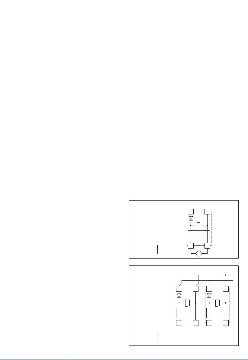
Схема соединения
Параллельное подключение
Схема соединения
Одиночное подключение
НАПРЯЖЕНИЕ ПИТАНИЯ:
В качестве защиты от неправильного подключения рабочего напряжения в
данный вариант прибора интегрирован однополупериодный выпрямитель
или диод защиты от напряжения обратной полярности. В случае приборов,
рассчитанных на напряжение 0 – 10 В, этот встроенный выпрямитель
допускает также эксплуатацию при питании напряжением переменного тока.
Выходной сигнал следует снимать измерительным прибором. Выходное
напряжение при этом измеряется относительно нулевого потенциала (0 В)
входного напряжения!
Если прибор запитывается напряжением
постоянного тока
, следует исполь-
зовать вход рабочего напряжения UB+ (для питания напряжением 15...36 В)
и UB– ⁄ GND (в качестве корпуса)!
Если для питания нескольких приборов используется напряжение 24В
переменного тока,
необходимо следить за тем, чтобы все положительные
входы рабочего напряжения (+) полевых устройств были соединены друг с
другом. Это относится также ко всем отрицательным входам рабочего
напряжения (–) = опорного потенциала (синфазное подключение полевых
устройств). Все выходы полевых устройств должны относиться к одному
потенциалу!
Подключение питающего напряжения одного из полевых устройств с неверной
полярностью ведёт к короткому замыканию напряжения питания. Ток короткого
замыкания, протекающий через данное устройство, может привести к его
повреждению.
Следите за правильностью проводки!
Circuitry Circuitry
0...10V
0V/GND
0...10V
0V/GND
Power supply
AC 24V~ 0V
DC 15-36V = GND
Circuitry
0...10V
0V/GND
V
Power supply
AC 24V~ 0V
DC 15-36V = GND
r Указания к продуктам
В качестве Общих Коммерческих Условий имеют силу исключительно наши Условия, а также действительные «Общие условия поставки продукции
и услуг для электрической промышленности» (ZVEI) включая дополнительную статью «Расширенное сохранение прав собственности».
Помимо этого, следует учитывать следующие положения:
– Перед установкой и вводом в эксплуатацию следует прочитать данное руководство; должны быть учтены все приведенные в нем указания!
– Подключение прибора должно осуществляться исключительно к безопасно малому напряжению и в обесточенном состоянии.
Во избежание повреждений и отказов (например, вследствие наводок) следует использовать экранированную проводку, избегать
параллельной прокладки токоведущих линий и учитывать предписания по электромагнитной совместимости.
– Данный прибор следует применять только по прямому назначению, учитывая при этом соответствующие предписания VDE
(союза немецких электротехников), требования, действующие в Вашей стране, инструкции органов технического надзора и местных
органов энергоснабжения. Надлежит придерживаться требований строительных норм и правил, а также техники безопасности и
избегать угроз безопасности любого рода.
– Мы не несем ответственности за ущерб и повреждения, возникающие вследствие неправильного применения наших устройств.
– Ущерб, возникший вследствие неправильной работы прибора, не подлежит устранению по гарантии.
– Установка приборов должна осуществляться только квалифицированным персоналом.
– Действительны исключительно технические данные и условия подключения, приведенные в поставляемых с приборами руководствах
по монтажу и эксплуатации. Отклонения от представленных в каталоге характеристик дополнительно не указываются, несмотря на их
возможность в силу технического прогресса и постоянного совершенствования нашей продукции.
– В случае модификации приборов потребителем гарантийные обязательства теряют силу.
– Не разрешается использование прибора в непосредственной близости от источников тепла (например, радиаторов отопления)
или создаваемых ими тепловых потоков; следует в обязательном порядке избегать попадания прямых солнечных лучей или теплового
излучения от аналогичных источников (мощные осветительные приборы, галогенные излучатели).
– Эксплуатация вблизи оборудования, не соответствующего нормам электромагнитной совместимости (EMV), может влиять на работу
приборов.
– Недопустимо использование данного прибора в качестве устройства контроля ⁄ наблюдения, служащего исключительно для защиты
людей от травм и угрозы для здоровья ⁄ жизни, а также в качестве аварийного выключателя устройств и машин или для аналогичных задач
обеспечения безопасности.
– Размеры корпусов и корпусных принадлежностей могут в определённых пределах отличаться от указанных в данном руководстве.
– Изменение документации не допускается.
– В случае рекламаций принимаются исключительно цельные приборы в оригинальной упаковке.
Перед установкой и вводом в эксплуатацию следует прочитать данное руководство; должны быть учтены все приведенные в нем указания!
13 14
# 14-4141 (wie Katalog-2014, ab Seite 154)1. KORREKTUR | 21. 01. 2014 ⁄ PR # 20400 - 2014

THERMASREG® FS
D G F r
Irrtümer und technische Änderungen vorbehalten.
Errors and technical changes excepted.
Sous réserve d’erreurs et de modifications techniques.
Возможны ошибки и технические изменения.
Anschlussbild
FS
Connecting diagram
FS
Schéma de raccordement
Схема подключения
1 2 3 4 5 6 7 8
x x
ON
1 2
min. max.
B
W
A
+UB
GND
Temp.
ST-E
AV
GND
+UB
Temp.
ST-E
AV
A
W
B
ON
1 2
Taster
Kalibrierung
Taster
Reset
LED Alarm
Frostschutz Einstellung
Schaltschwelle
LED Anzeige Ist-Temp.
bzw. Schaltschwelle
LED Anzeige Ist-Temperatur
bzw. Schaltschwelle (in °C)
DIP-Schalter
Anschluss
Heizelement
(optional)
Betriebsspannung GND
Betriebsspannung 24V AC/DC
Ausgang Temperatur 0-10V = 0...15°C
Steuereingang 0-10V
Summationsausgang 0-10V (optional)
Kontakt B
Kontakt W – Wechsler (24 V)
Kontakt A
0
+1,5
auto
0...+15 °C manuell
nicht
belegt +3,0
+4,5
+6,0
+7,5
+9,0
+10,5
+12,0
+13,5
+15,0
1 2 3 4 5 6 7 8
x x
ON
1 2
min. max.
B
W
A
+UB
GND
Temp.
ST-E
AV
GND
+UB
Temp.
ST-E
AV
A
W
B
ON
1 2
Calibration
button
Reset
button
Frost
protection
alarm LED
Switching
threshold
adjustment
LED indicator ACTUAL temp.
resp. switching threshold
LED indicator ACTUAL
temperature resp.
switching threshold (in °C)
DIP switches
Connection
for heating
element
(optional)
Operating voltage GND
Operating voltage 24V AC/DC
Output temperature 0-10V = 0...15°C
Control input 0-10V
Summation output 0-10V (optional)
Contact B
Contact W – changeover (24 V)
Contact A
0
+1.5
auto
0...+15 °C Manual
Not
assigned +3.0
+4.5
+6.0
+7.5
+9.0
+10.5
+12.0
+13.5
+15.0
© Copyright by S+S Regeltechnik GmbH
Nachdruck, auch auszugsweise, nur mit Genehmigung von S+S Regeltechnik GmbH gestattet.
Reprints, in part or in total, are only permitted with the approval of S+S Regeltechnik GmbH.
La reproduction des textes même partielle est uniquement autorisée après accord de la société S+S Regeltechnik GmbH.
Перепечатка, в том числе в сокращенном виде, разрешается лишь с согласия S+S Regeltechnik GmbH.
15 16
# 14-4141 (wie Katalog-2014, ab Seite 154)1. KORREKTUR | 21. 01. 2014 ⁄ PR # 20400 - 2014

D G F r
KRD - 04
Maßzeichnung
KRD - 04
Dimensional drawing
Plan coté
Габаритный чертеж
Maßzeichnung
MK - 05 - K
Dimensional drawing
Plan coté
Габаритный чертеж
MK - 05 - K
Zubehör
Accessories
Accessoires
Принадлежности
15 16
# 14-4141 (wie Katalog-2014, ab Seite 154)1. KORREKTUR | 21. 01. 2014 ⁄ PR # 20400 - 2014
This manual suits for next models
4
Table of contents
Languages:
Other S+S Regeltechnik Thermostat manuals

S+S Regeltechnik
S+S Regeltechnik HYGRASREG RH-2 Repair manual

S+S Regeltechnik
S+S Regeltechnik HYGRASGARD RFTF-Modbus Repair manual

S+S Regeltechnik
S+S Regeltechnik THERMASGARD RTM1-U LCD Repair manual

S+S Regeltechnik
S+S Regeltechnik THERMASREG FST Repair manual

S+S Regeltechnik
S+S Regeltechnik FST-3 Repair manual

S+S Regeltechnik
S+S Regeltechnik ThermAsreg FS-20 Repair manual

S+S Regeltechnik
S+S Regeltechnik Thermasreg RTR-S Series Repair manual

S+S Regeltechnik
S+S Regeltechnik RF 642 2-00 Series User manual

S+S Regeltechnik
S+S Regeltechnik THERMASGARD RTM1 User manual

S+S Regeltechnik
S+S Regeltechnik RYMASKON 500 - BACnet User manual


