REMS Solar-Push I 80 User manual

REMS GmbH & Co KG
Maschinen- und Werkzeugfabrik
Stuttgarter Straße 83
71332 Waiblingen
Deutschland
Telefon +49 7151 1707-0
Telefax +49 7151 1707-110
www.rems.de
REMS Solar-Push I 80
REMS Solar-Push K 60
for Professionals
deu Betriebsanleitung
...............................................
3
eng Instruction Manual
.............................................
7
fra Notice d’utilisation
............................................
11
ita Istruzioni d’uso
.................................................
15
spa Instrucciones de servicio
................................
19
nld Handleiding
.......................................................
23
swe Bruksanvisning
................................................
27
nno Bruksanvisning
................................................
31
dan Brugsanvisning
................................................
35
fi n Käyttöohje
.........................................................
39
por Manual de instruções
.......................................
43
pol Instrukcja obsługi
.............................................
47
ces Návod k použití
.................................................
51
slk Návod na obsluhu
............................................
55
hun Kezelési utasítás
..............................................
59
hrv Upute za rad
......................................................
63
srp Uputstvo za rad ................................................ 67
slv Navodilo za uporabo
........................................
71
ron Manual de utilizare
...........................................
75
rus Руководство по эксплуатации
.....................
79
ell Οδηγίες χρήσης
................................................
83
tur Kullanım kılavuzu
.............................................
87
bul Ръководство за експлоатация
.....................
91
lit Naudojimo instrukcija
......................................
95
lav Lietošanas instrukcija
......................................
99
est Kasutusjuhend
...............................................
103

Fig. 1 Solar-Push I 80
Fig. 2 Solar-Push K 60
6
6
3
3
2
2
4
4
5
5
1
1
7
7
8
9
Fig. 3
Fig. 4
Fig. 5
10
Fig. 6
Fig. 6

eng eng
Translation of the Original Instruction Manual
Fig. 1–6
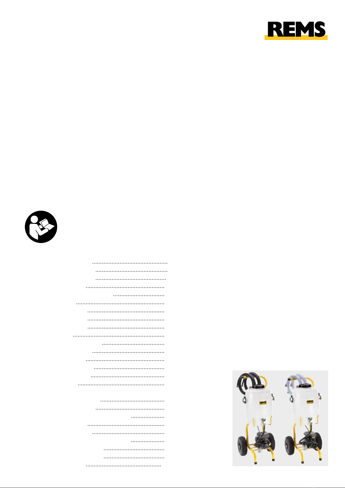
1 Connection pressure line
2 Connection return line
3 Plastic tank
4 Ball valve
5 On / Off switch
6 Large opening with screw cover
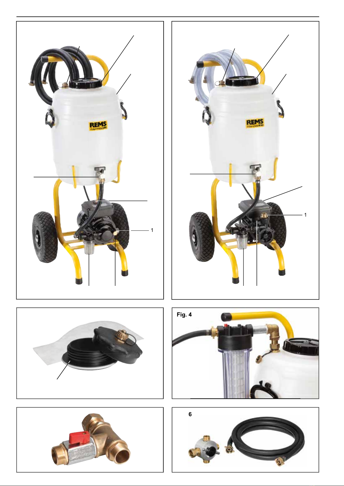
7 Inspection glass, fi ne fi lter
8 Pressure relief valve
(Solar-Push I 80,
accessory for Solar-Push K 60,
art.-no. 115217)
9 Bleed screw
(Solar-Push K 60)
10 Adapter
General power tool safety warnings
WARNING
WARNING
Read all safety warnings, instructions, illustrations and specifi cations provided
with this power tool.
Failure to follow all instructions listed below may result in
electric shock, fi re and/or serious injury.
Save all warnings and instructions for future reference.
The term “power tool” in the warnings refers to your mains-operated (corded) power
tool or battery-operated (cordless) power tool.
1) Work area safety
a) Keep work area clean and well lit.
Cluttered or dark areas invite accidents.
b) Do not operate power tools in explosive atmospheres, such as in the pres-
ence of fl ammable liquids, gases or dust.
Power tools create sparks which
may ignite the dust or fumes.
c) Keep children and bystanders away while operating a power tool.
Distrac-
tions can cause you to lose control.
2) Electrical safety
a) Power tool plugs must match the outlet. Never modify the plug in any
way. Do not use any adapter plugs with earthed (grounded) power tools.
Unmodifi ed plugs and matching outlets will reduce risk of electric shock.
b) Avoid body contact with earthed or grounded surfaces, such as pipes,
radiators, ranges and refrigerators.
There is an increased risk of electric shock
if your body is earthed or grounded.
c) Do not expose power tools to rain or wet conditions.
Water entering a power
tool will increase the risk of electric shock.
d) Do not abuse the cord. Never use the cord for carrying, pulling or unplug-
ging the power tool. Keep cord away from heat, oil, sharp edges or moving
parts.
Damaged or entangled cords increase the risk of electric shock.
e) When operating a power tool outdoors, use an extension cord suitable for
outdoor use.
Use of a cord suitable for outdoor use reduces the risk of electric
shock.
f) If operating a power tool in a damp location is unavoidable, use a residual
current device (RCD) protected supply.
Use of an RCD reduces the risk of
electric shock.
3) Personal safety
a) Stay alert, watch what you are doing and use common sense when oper-
ating a power tool. Do not use a power tool while you are tired or under
the infl uence of drugs, alcohol or medication.
A moment of inattention while
operating power tools may result in serious personal injury.
b) Use personal protective equipment. Always wear eye protection.
Protec-
tive equipment such as a dust mask, non-skid safety shoes, hard hat or hearing
protection used for appropriate conditions will reduce personal injuries.
c) Prevent unintentional starting. Ensure the switch is in the off-position before
connecting to power source and/or battery pack, picking up or carrying the
tool.
Carrying power tools with your fi nger on the switch or energising power
tools that have the switch on invites accidents.
d) Remove any adjusting key or wrench before turning the power tool on.
A
wrench or a key left attached to a rotating part of the power tool may result in
personal injury.
e) Do not overreach. Keep proper footing and balance at all times.
This enables
better control of the power tool in unexpected situations.
f) Dress properly. Do not wear loose clothing or jewellery. Keep your hair and
clothing away from moving parts.
Loose clothes, jewellery or long hair can be
caught in moving parts.
g) If devices are provided for the connection of dust extraction and collec-
tion facilities, ensure these are connected and properly used.
Use of dust
collection can reduce dust-related hazards.
h) Do not let familiarity gained from frequent use of tools allow you to become
complacent and ignore tool safety principles.
A careless action can cause
severe injury within a fraction of a second.
4) Power tool use and care
a) Do not force the power tool. Use the correct power tool for your application.
The correct power tool will do the job better and safer at the rate for which it was
designed.
b) Do not use the power tool if the switch does not turn it on and off.
Any power
tool that cannot be controlled with the switch is dangerous and must be repaired.
c) Disconnect the plug from the power source and/or remove the battery pack,
if detachable, from the power tool before making any adjustments, changing
accessories, or storing power tools.
Such preventive safety measures reduce
the risk of starting the power tool accidentally.
d) Store idle power tools out of the reach of children and do not allow persons
unfamiliar with the power tool or these instructions to operate the power
tool.
Power tools are dangerous in the hands of untrained users.
e) Maintain power tools and accessories. Check for misalignment or binding
of moving parts, breakage of parts and any other condition that may affect
the power tool’s operation. If damaged, have the power tool repaired before
use.
Many accidents are caused by poorly maintained power tools.
f) Keep cutting tools sharp and clean.
Properly maintained cutting tools with
sharp cutting edges are less likely to bind and are easier to control.
g) Use the power tool, accessories and tool bits etc. in accordance with these
instructions, taking into account the working conditions and the work to be
performed.
Use of the power tool for operations different from those intended
could result in a hazardous situation.
h) Keep handles and grasping surfaces dry, clean and free from oil and grease.
Slippery handles and grasping surfaces do not allow for safe handling and control
of the tool in unexpected situations.
5) Service
a) Have your power tool serviced by a qualifi ed repair person using only
identical replacement parts.
This will ensure that the safety of the power tool
is maintained.
Safety Instructions for Electrical Filling and Flushing Unit
WARNING
WARNING
Read all safety warnings, instructions, illustrations and specifi cations provided
with this power tool.
Failure to follow all instructions listed below may result in
electric shock, fi re and/or serious injury.
Save all warnings and instructions for future reference.
●
Do not use the electrical device if it is damaged.
There is a danger of accident.
●
Only connect the power tool of protection class I to a socket/extension lead
with a functioning PE conductor.
There is a danger of electric shock.
●
Examine the hoses and seals for damage every time before using.
Damaged
hoses can burst and cause injury.
●
Only use original hoses, fi ttings and couplings for the electrical device.
This ensures that the safety of the electrical device is maintained.
●
Apply the electrical device horizontally and dry for operation.
Penetration
of water into the electrical device increases the risk of electric shock.
●
Do not aim liquid jets at the electrical device, not even for cleaning.
Penetration of water into the electrical device increases the risk of electric shock.
●
Do not suck up infl ammable or explosive liquids, for example petrol, oil,
alcohol, solvent, with the power tool.
The fumes or liquids can ignite or explode.
●
Do not operate the electrical device in rooms where there is a risk of explo-
sion.
The fumes or liquids can ignite or explode.
●
Protect the electrical device against frost.
The electrical device could be
damaged. Empty the pump body, the plastic tank and the hoses of the electrical
device.
●
Never let the electrical device operate unattended. Switch off the power
tool during longer work breaks, pull out the mains plug and remove all
hoses/plugs.
Electrical devices can cause hazards which lead to material damage
or injury when left unattended.
●
Do not operate the electrical device on a closed pipe system for a prolonged
period of time.
The electrical device could be damaged by overheating.
●
Children and persons who, due to their physical, sensory or mental abilities
or lack of experience and knowledge are unable to operate the electrical
device safely may not use this electrical device without supervision or
instruction by a responsible person.
Otherwise there is a risk of operating
errors and injuries.
●
Only allow trained persons to use the electrical device.
Apprentices may only
operate the electrical device when they are older than 16, when this is necessary
for their training and under the supervision of a trained operative.
●
Check the power cable of the electrical device and the extension leads
regularly for damage.
Have these renewed by qualifi ed experts or an authorised
REMS customer service workshop in case of damage.
●
Only use approved and appropriately marked extension leads with a suffi -
cient cable cross-section.
Use extension leads up to a length of 10 m with
cable cross-section 1.5 mm², from 10–30 m with cable cross-section 2.5 mm².
Explanation of symbols
WARNING
WARNING
Danger with a medium degree of risk which could result in
death or severe injury (irreversible) if not heeded.
CAUTION
CAUTION
Danger with a low degree of risk which could result in minor
injury (reversible) if not heeded.
NOTICE
NOTICE
Material damage, no safety note! No danger of injury.
Read the operating manual before starting
Power tool complies with protection class I
Environmentally friendly disposal
CE conformity mark
7

eng eng
1. Technical data
Use for the intended purpose
WARNING
WARNING
Only use REMS Solar-Push for the intended purpose of fi lling, fl ushing and venting
solar systems, geothermal systems and fl oor/wall heater systems and for fi lling
tanks. Permissible media: heat transfer liquids, antifreeze, water, aqueous solutions,
emulsions.
All other uses are not for the intended purpose and are prohibited.
1.1. Scope of Supply
Electrical fi lling and fl ushing unit, 2 fl exible fabric hoses, instruction manual
1.2. Article numbers
REMS Solar-Push K 60 115302
REMS Solar-Push I 80 115301
PVC fabric hose ½" T60 115314
EPDM fabric h
ose ½" T100 115315
EPDM fabric hose ½" T165 115319
30 l plastic tank 115375
Pressure relief valve 115217
Fine fi lter with fi lter cartridge 90 μm 115323
Fine fi lter cartridge 90 μm 043054
Fine fi lter with fi ne fi lter bag 70 μm 115220
Fine fi lter bag 70 μm (10 bags) 115221
Adapter for canister lid 115379
Shut-off valve ¾" 115324
Changeover valve 115325
Changeover valve fl ow direction 115326
REMS CleanM 140119
1.3. Applications Solar-Push I 80 Solar-Push K 60
Plastic tank volume 30 l 30 l
Transport height ≤ 63 m ≤ 54 m
Volume fl ow ≤ 1.6 m
3
/h ≤ 3 m
3
/h
Transport capacity at
40 m pumping head 18 l/min 16 l/min
Transport volume
≤
27 l/min ≤
36 l/min
Transport pressure
≤
0.65 MPa/6.5 bar
≤
0.55 MPa/5.5 bar
94 psi 80 psi
Temperature of the transpor-
ted media (constant load) ≤ 8
0 °
C ≤ 6
0 °
C
pH value of the
transported media 6.5–9.5 6.5–9.5
1.4. Electrical data
230 V~; 50 Hz; 230 V~; 50 Hz;
1000 W
940
W
110 V~; 50 Hz;
940
W
Protection class I I
Type of protection IP 55 IP 44
Operating mode S3 50% (
AB
5/10 min) Continuous
operation
1.5. Dimensions
L×W× H 550×480× 970 mm 550 ×480× 970 mm
(21.7"×18.9"× 38.3") (21.7" × 18.9"×38.3")
1.6. Weights
with PVC fabric hoses 20.4 kg (45 lb)
20,2 kg (44.5 lb)
with EPDM fabric hoses 20.0 kg (44.2 lb)
20.5 kg (45.2 lb)
1.7. Noise information
Workplace-related
emissions value L
pA
= 73 dB (A) L
pA = 73 dB (A) LpA
pA
= 70 dB (A)
pA = 70 dB (A)pA
K = 3 dB (A) K = 3 dB (A)
1.8. Suction and pressure hoses PVC- EPDM- EPDM-
fabric fabric fabric
hose T60 hose T100 hose T165
Hose length 3 m 3 m 3 m
Hose size ½" ½" ½"
Hose connector, both sides ¾" ¾" ¾"
Temperature resistance ≤ 6
0 °
C ≤ 10
0 °
C ≤ 16
5 °
C
1.9. Fine fi lter with fi ne fi lter bag 90 µm (accessory Art. No. 115323)
Rated width DN 70
Rated volume fl ow at pressure loss 5m3/h at 20 kPa/0,2 bar/2,9 psi
Rated pressure 300 kPa/3 bar/43,5 psi
Operating temperature ≤ 4
5 °
C
Operating pressure ≤ 800 kPa/8 bar/116 psi
2. Start-up
NOTICE
NOTICE
REMS Solar-Push is not intended/suitable for permanent connection to the
installation. Disconnect all hoses from the installation after completing the work.
REMS Solar-Push may not be operated unattended.
2.1. Electrical connection
WARNING
WARNING
Caution: Mains voltage present!
Before connecting the electrical fi lling and
fl ushing unit, check whether the voltage given on the rating plate corresponds
to the mains voltage.
Only connect electrical devices of protection class I to a
socket/extension lead with a functioning protective contact. On building sites,
in a wet environment, indoors and outdoors or under similar installation condi-
tions, only operate the electr
ical device on the mains with a fault current
protection switch (RCD) which interrupts the power supply as soon as the
leakage current to earth exceeds 30 mA for 200 ms.
2.2. Connecting the electrica
l fi lling and fl ushing unit to the solar system
Connect one of the two fabric hoses to the pressure line connection (1). Connect
the 2nd fabric ho
se to the return line connection (2) of the plastic tank (3).
Connect the respective free end of the pressure or return line to the ball valves
of the solar system and open the ball valves. Close the connecting valve between
the two ball valves of the solar system. Fill the plastic tank (3) with transported
medium and open the ball valve (4). Plug the mains plug of the electrical fi lling
and fl ushing unit into the socket with a protective earth.
CAUTION
CAUTION
Danger of injury due to escaping transported medium.
Tighten the hose
screw connections and check for leaks regularly.
2.3. Screw cover with return line connection ¾" and fi ne fi lter bag 70 μm
(accessory art. no. 115220, Fig. 3)
Remove the screw cover (6). Replace the inner plate of the screw cover (6) by
an adapter (10). Screw the screw cover (6) with adapter to the plastic tank.
Insert the fi ne fi lter into the opening in the adapter, screw the screw cover with
¾" return line connection to the adapter, screw the return line to the return line
connection, close the return pipe (2) connection.
2.4. Fine fi lter unit with large dirt collection vessel (accessory art. no. 115323,
Fig. 4)
Fasten the fi ne fi lter unit to the return line connection (2), connect the return
line to the fi ne fi lter unit.
2.5. Changeover valve for alternative suction of the transport medium from
another tank (accessory art. no. 115325, Fig. 5)
Unscrew the line from the plastic tank (3) to the pump at the ball valve (4) and
screw on the changeover valve for alternative suction of the transport medium
at the ball valve (4). Connect one outlet of the T-piece to the pump line, connect
a line to another tank to the other outlet of the T-piece. Control the fl ow direction
with the valve handle.
2.6. Flow direction changeover valve (accessory art. no. 115326, Fig. 6)
The fl ow direction changeover valve serves for clearing deposits/sludge in solar
stations and underfl oor heating. Screw the fl ow direction changeover valve with
connection (P) to the pressure line connection (1). Connect connection (R) of
the fl ow direction changeover valve and the return line connection (2) with the
enclosed ½" T100 EPDM fabric hose. The two "solar station" connections on
the fl ow direction changeover valve are connected to the outlets on the solar
station with the two ½" fabric hoses belonging to the REMS Solar-Push.
The
pressure line and return line to and from the solar station are switched by turning
the lever on the fl ow direction changeover valve with the pump running.
Deposits/
sludge are loosened by the generated pressure pulses.
3. Operation
NOTICE
NOTICE
REMS Solar-Push is not intended/suitable for permanent connection to the
installation. Disconnect all hoses from the installation after completing the work.
REMS Solar-Push may not be operated unattended.
Do not switch the Solar-Push K 60 pump on until it is fi lled completely with
liquid. Do not allow the pump to run dry! Procedure for fi lling the Solar-Push K
60: The plastic tank (3) must be fi lled with liquid. The pressure line (1) and
return line (2) must be connected. Open the ball valve (4). Open the bleed
screw (9). Close the bleed screw (9) as soon as liquid emerges.
The pump of the Solar-Push I 80 also sucks dry.
Switch the pump on at the On / Off switch (5). Open and remove the screw
cover (6) on the plastic tank (3) so that the air can escape from the system.
Observe the liquid level in the plastic tank and, if necessary, refi ll with transported
medium so that no air enters the solar circuit. Flush the solar circuit with the
transported medium. At the inspection glass of the fi ne fi lter (7) or by looking
into the large opening of the plastic tank (6), check whether there are still air
bubbles in the transported medium. Continue the fl ushing process until there
is no more air in the transported medium.
Do not close the pressure and return lines of both pumps for longer than 60 s
because the pumps otherwise run hot and will be damaged.
Switch off the pump (5) after the end of the fi lling and fl ushing process. Close
the ball valves on the solar system, open the conneting valve between the two
ball valves of the solar system. Close the ball valve (4). On the REMS Solar-Push
I 80, reduce the pressure in the pressure line by opening the pressure relief valve
(8). On the REMS Solar-Push K60, reduce the pressure in the pressure line by
slightly unscrewing the inspection glass on the fi ne fi lter (7). The pressure relief
valve (8) is available as an accessory for the REMS Solar-Push K 60.
8

eng eng
CAUTION
CAUTION
Danger of scalding at high transported medium temperature.
Fill the system
only when it is in its cold state; cover the solar collectors if necessary.
First unscrew the pressure and return lines on the fi lling and fl ushing unit, connect
the open hose ends with a connecting piece, e.g. ¾" double nipple in order to
prevent transported medium from dripping of running out during transport.
NOTICE
NOTICE
Avoid environmental damage from outfl owing transported media.
Collect
outfl owing transported medium immediately and dispose of it in accordance
with the national regulations that apply.
To fl ush heavily contaminated systems,
e. g. underfl oor heating and to clear
slurries, use a fi ne fi lter unit with a large dirt collection vessel (accessory)
(page
2.4.) or a screw lid with return connection ¾” and fi ne fi lter bag 70 μm
(accessory) (see 2.3.).
NOTICE
NOTICE
Danger of frost:
If the pump is exposed to temperatures ≤
5 °
C, the pump
body, the plastic tank and the hoses must be completely emptied to avoid
damage. This procedure is also recommended at normal temperatures when
the pump is not used for long periods of time.
4. Maintenance
Notwithstanding the maintenance described below, it is recommended to send
in the electrical fi lling and fl ushing unit to an authorised REMS contract customer
service workshop for inspection and periodic testing of electrical devices at
least once a year.
In Germany, such periodic testing of electrical devices should
be performed in accordance with DIN VDE 0701-0702 and also prescribed for
mobile electrical equipment according to the accident prevention rules DGUV,
regulation 3 "Electrical Systems and Equipment". In addition, the respective
national safety provisions, rules and regulations valid for the application site
must be considered and observed.
4.1. Maintenance
WARNING
WARNING
Pull out the mains plug before maintenance work!
Clean the pump regularly in order to prevent the pump parts from sticking,
particularly if they are not used for a n extended period. Store the pump in a
frost-proof location. Check hoses, hose connectors and seals for damage before
every use. Do no used damaged hoses and seals.
Check the fi ne fi lter of the pump for contamination regularly through the sight
glass (7) and clean if necessary. To do this, unscrew the sight glass (7) on the
fi le fi lter, remove the fi lter screen and clean both under running water or with
compressed air. Replace damaged fi lters.
Clean plastic parts (e.g. housing) only with REMS CleanM machine cleaner
(Art. No. 140119) or a mild soap and a damp cloth. Do not use household
cleaners. These often contain chemicals which can damage the plastic parts.
Never use petrol, turpentine, thinner or similar products for cleaning.
Make sure that liquids never get onto or inside the pump motor.
4.2. Inspection / maintenance
WARNING
WARNING
Pull out the mains plug before carrying out maintenance or repair work!
This work may only be performed by qualifi ed personnel.
5. Faults
WARNING
WARNING
Switch off the On/Off switch and pull out the mains plug before repairing the fault on the electrical fi lling and fl ushing unit.
5.1.
Fault:
Pump does not suck up or is not working.
Cause:
Remedy:
●
Unsuitable transport medium.
●
Only use approved transport media (see 1. Intended Use and 1.3.).
●
Leaking suction pipe.
●
Change seal/suction pipe.
●
Suction pipe or fi ne fi lter blocked.
●
Clear the blockage in the suction pipe. Clean fi le fi lter7fi lter screen (see 4.1.)
or change fi lter screen.
●
Pressure hose is blocked.
●
Clear the blockage in the pressure hose.
●
Ball valve (4) is closed.
●
Open ball valve.
●
The plastic tank (3) is empty.
●
Fill or refi ll the plastic tank with transport medium (see 3. Operation).
●
Air in the pump (Solar-Push K 60).
●
Fill liquid into pump (see 3. Operation).
●
Pump has seized (Solar-Push K 60).
●
Push a fl at screwdriver through the middle hole in the motor fan cover and
release the blockage by turning abruptly to the left and right several times.
●
Power cable defective.
●
Have the power cable changed by qualifi ed personnel or an authorised REMS
customer service workshop.
●
Pump/motor defective.
●
Have the pump/motor checked/repaired by an authorised REMS customer
service workshop.
5.2.
Fault:
Pump builds up no pressure or does not transport the medium.
Cause:
Remedy:
●
Transport height exceeded.
●
Check transport height (see 1.3.).
●
Unsuitable transport medium.
●
Only use approved transport media (see 1. Intended Use and 1.3.).
●
Ball valves/solar unit connecting valve not opened/closed correctly.
●
Open/closed ball valves according to 2.2.
●
Fine fi lter blocked.
●
Clean the fi ne fi lter/fi lter screen (see 4.1.) or change the fi lter screen.
●
Pump/motor defective.
●
Have the pump/motor checked/repaired by an authorised REMS customer
service workshop.
5.3.
Fault:
Liquid escapes from the pump.
Cause:
Remedy:
●
Seals of the pump connections are defective.
●
Change seals.
●
Pump seals are defective.
●
Have the pump checked/repaired by an authorised REMS customer service
workshop.
9

eng eng
6. Disposal
The electrical fi lling and fl ushing unit may not be thrown in the domestic waste
after use. It must be disposed of properly by law.
7. Manufacturer’s Warranty
The warranty period shall be 12 months from delivery of the new product to the
fi rst user. The date of delivery shall be documented by the submission of the
original purchase documents, which must include the date of purchase and the
designation of the product. All functional defects occurring within the warranty
period, which are clearly the consequence of defects in production or materials,
will be remedied free of charge. The remedy of defects shall not extend or
renew the warranty period for the product. Damage attributable to natural wear
and tear, incorrect treatment or misuse, failure to observe the operational
instructions, unsuitable operating materials, excessive demand, use for unau-
thorized purposes, interventions by the customer or a third party or other
reasons, for which REMS is not responsible, shall be excluded from the warranty
Services under the warranty may only be provided by customer service stations
authorized for this purpose by REMS. Complaints will only be accepted if the
product is returned to a customer service station authorized by REMS without
prior interference and in a fully assembled condition. Replaced products and
parts shall become the property of REMS.
The user shall be responsible for the cost of shipping and returning the product.
A list of the REMS-authorized customer service stations is available on the
Internet under www.rems.de. For countries which are not listed, the product
must be sent to the SERVICE-CENTER, Neue Rommelshauser Strasse 4,
71332 Waiblingen, Deutschland. The legal rights of the user, in particular the
right to make claims against the seller in case of defects as well as claims due
to wilful violation of obligations and claims under the product liability law are
not restricted by this warranty.
This warranty is subject to German law with the exclusion of the confl ict of laws
rules of German International Private Law as well as with the exclusion of the
United Nations Convention on Contracts for the International Sales of Goods
(CISG). Warrantor of this world-wide valid manufacturer’s warranty is REMS
GmbH & Co KG, Stuttgarter Str. 83, 71332 Waiblingen, Deutschland.
8. Spare parts lists
For spare parts lists, see www.rems.de → Downloads → Parts lists.
10
Other manuals for Solar-Push I 80
1
This manual suits for next models
1
Table of contents
Popular Inverter manuals by other brands

Sofar solar
Sofar solar ME 5KTL-3PH user manual

Tripp Lite
Tripp Lite PowerVerter PV700HF owner's manual

Tripp Lite
Tripp Lite APSWX Series owner's manual

Tripp Lite
Tripp Lite PowerVerter APS700HF owner's manual

Delta
Delta SI 5000 Operation and installation manual

CanadianSolar
CanadianSolar CSI-75K-T480GL03-U Installation and operation manual