Rena Systems XPS-Pro User manual

RENA Systems Inc. would like to Thank You for investing in our
quality built products.
Please record the following information for future reference:
Model:
Serial Number:
Purchase Date:
Purchased From:
Dealer Name:
Contact Name:
Address:
Address:
Phone Number:
Please take this opportunity to register your product.
Use the following “Warranty Registration” link to register your product.
http://www.renausa.com/support_warranty_registration.html

SAFETY PRECAUTIONS
THIS EQUIPMENT PRESENTS NO PROBLEM WHEN USED PROPERLY. HOWEVER, CERTAIN SAFETY
RULES SHOULD BE OBSERVED WHEN OPERATING THE SHUTTLE FEEDER.
BEFORE USING THE FEEDER, YOU SHOULD READ THIS MANUAL CAREFULLY AND FOLLOW THE
RECOMMENDED PROCEDURES, SAFETY WARNINGS, AND INSTRUCTIONS:
Keep hands, hair, and clothing clear of rollers and other moving parts.
Avoid touching moving parts or materials while the machine is in use. Before clearing a jam, be sure machine
mechanisms come to a stop.
Always turn off the machine before making adjustments, cleaning the machine, or performing any maintenance
covered in this manual.
Use the power cord supplied with the machine and plug it into a properly grounded wall outlet located near the
machine and easily accessible. Failure to properly ground the machine can result in sever personal injury and/or
fire.
The power cord and wall plug is the primary means of disconnecting the machine from the power supply.
DO NOT use an adapter plug on the line cord or wall outlet.
DO NOT remove the ground pin from the line cord.
DO NOT route the power cord over sharp edges or trapped between furniture.
Avoid using wall outlets that are controlled by wall switches, or shared with other equipment.
Make sure there is no strain on the power cord caused by jamming between the equipment, walls or furniture.
DO NOT remove covers. Covers enclose hazardous parts that should only be accessed by a qualified service
representative. Report any damage of covers to your service representative.
This machine requires periodic maintenance. Contact your authorized service representative for required
service schedules.
To prevent overheating, do not cover the vent openings.
Use this equipment only for its intended purpose.
In addition, follow any specific occupational safety and health standards for your workplace or area.
This manual is intended solely for the use and information of Neopost USA, its designated agents,
customers, and their employees. The information in this guide was obtained from several different
sources that are deemed reliable by all industry standards. To the best of our knowledge, that information
is accurate in all respects. However, neither Neopost USA, Inc. nor any of its agents or employees shall
be responsible for any inaccuracies contained herein.
Rena Systems Inc is a registered trademark of Neopost USA.
All other trademarks are the property of their respective holders.
All rights reserved. No part of this book may be reproduced or transmitted in any form or by any means, electronic or
mechanical, including photocopying, recording, or any information storage and retrieval system, without permission in
writing from the publisher

Table of Contents
SECTION 1 –GETTING ACQUAINTED ...................................................................................................................... 1
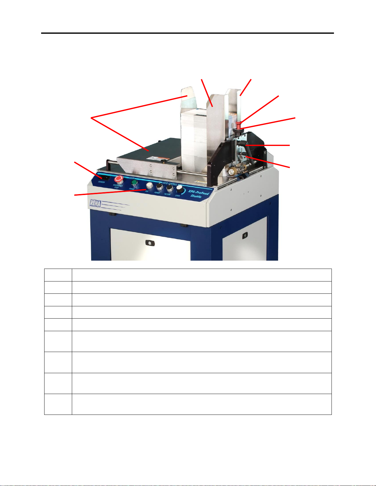
MAIN CONTROL PANEL....................................................................................................................................................2
MEDIA THICKNESS AND SEPARATOR KNOB ..........................................................................................................................2
SHEET LENGTH SWITCH....................................................................................................................................................2
SECTION 2 –INSTALLATION ................................................................................................................................... 3
POWER REQUIREMENTS...................................................................................................................................................3
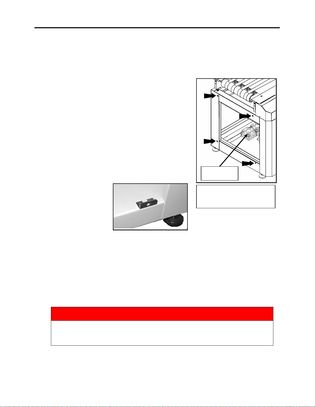
ATTACHING TO THE XPS-PROMAIL BASE ............................................................................................................................3
Connecting Power and Interface Controls to the XPS-ProMail Base......................................................................3
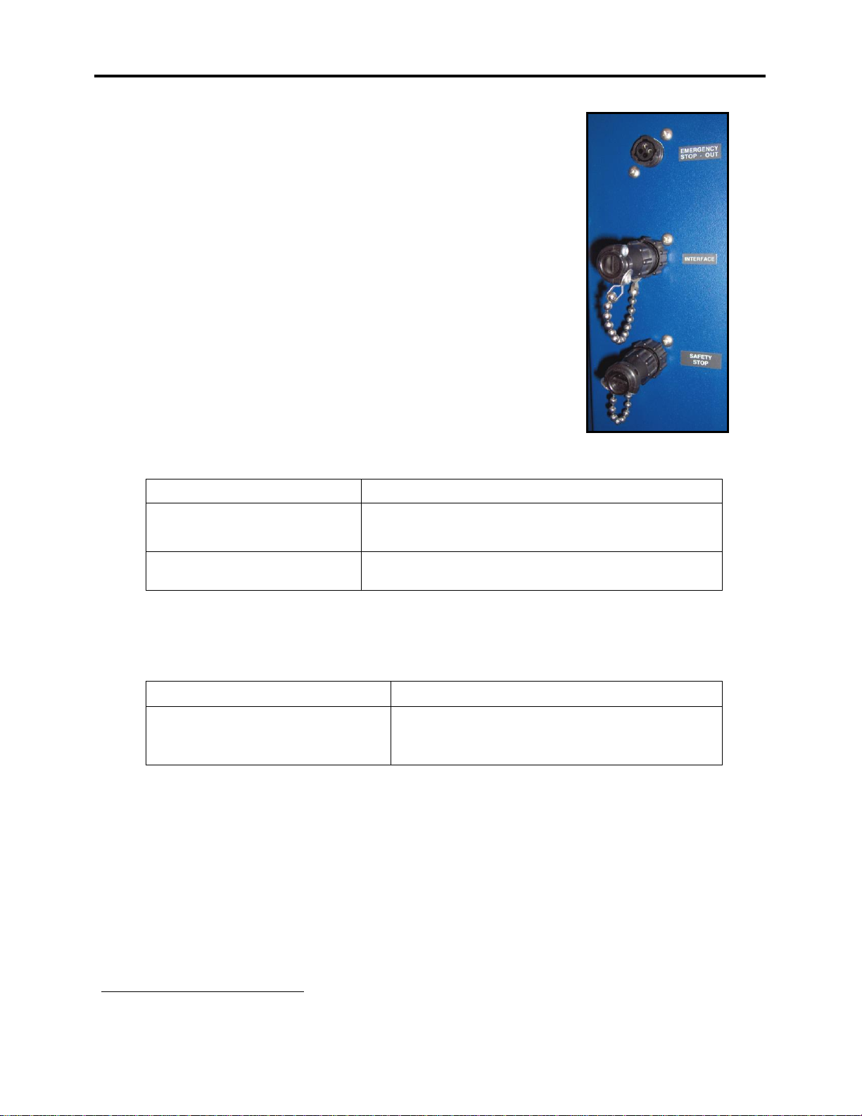
Feeder Interface Cables .........................................................................................................................................4
STAND-ALONE OPERATION ...............................................................................................................................................4
CONNECTING THE SHUTTLE FEEDER TO OTHER SYSTEMS.........................................................................................................5
SECTION 3 –SETUP AND OPERATION..................................................................................................................... 6
SETTING UP THE FEEDER ...................................................................................................................................................6
Step 1 - Verify the Vacuum Shuttle is at the “Home” Position ...............................................................................6
Step 2 - Choose and Install the Proper Vacuum Plate............................................................................................7
Installing Reversible Rear Media Sleds (Pusher).................................................................................................................. 8
Installing the Rear Media Support Accessory ...................................................................................................................... 9
Step 3 - Adjust the Forwarding Rollers to Accommodate the Media Thickness...................................................10
Step 4 - Adjust the Sheet Separator .....................................................................................................................10
Step 5 –Adjust the Guides ...................................................................................................................................11
Step 6 –Set the Sheet Length Switch...................................................................................................................11
OPERATING THE FEEDER.................................................................................................................................................11
FORWARDING ROLLER ALIGNMENT ADJUSTMENT ...............................................................................................................12
SECTION 4 - MAINTENANCE ................................................................................................................................. 14
General Cleaning..................................................................................................................................................14
Cleaning the Media Sensor ..................................................................................................................................14
CLEANING FEED ROLLERS ...............................................................................................................................................14
Cleaning the Jar Filter ..........................................................................................................................................15
CLEANING VACUUM PUMP FILTERS..................................................................................................................................15
SECTION 5 –TROUBLESHOOTING......................................................................................................................... 16
Feeder Power Won’t Turn ON (in Stand-Alone Mode):........................................................................................16
Feeder Power Won’t Turn ON (when Interfaced to XPS-ProMail Base):..............................................................16
Feeder Won’t Start to Feed (Forwarding Rollers turn but Vacuum Shuttle not moving):....................................16
Skewing:...............................................................................................................................................................16
Hesitation: ...........................................................................................................................................................17
Jamming: .............................................................................................................................................................17
Removing Jams in the Feeder ..............................................................................................................................17
APPENDIX –SPECIFICATIONS ............................................................................................................................... 18

Notes


GETTING ACQUAINTED
-1-
Section 1 –Getting Acquainted
1
Feeder Control Panel –See description of controls on next page.
2
Resettable Counter –This counter keeps track of the number of pieces fed.
3
Rear Guide –This guide keeps the media in the proper position for feeding.
4
Operator Side-Guide –This guide helps to position the media.
5
Non-Operator Side-Guide –This guide helps to position the media.
6
Sheet Separator Adjustment –This knob sets the depth of the sheet separator. (See
next page.)
7
Media Thickness Adjustment –This knob adjusts the height of the forwarding
rollers for proper feeding. (See next page.)
8
Roller Pressure Lever –This lever is used to release or engage pressure between the
Forwarding Rollers and Feed Rollers. (See next page.)
9
Locking Lever –This lever is used to secure the adjustment knob positions of the
Forwarding Roller and Sheet Separator adjustments.
1
2
3
4
5
6
7
8
9

GETTING ACQUAINTED
-2-
1
2
3
4
5
6
7
Main Control Panel
1
Resettable Counter –Keeps track of the number of pieces run.
2
Emergency STOP Button –This button will stop the feeder and lockout the controls.
3
Main Power Button –When the Emergency STOP switch is unlocked, this button will
turn on the power to the feeder.
4
Jog Button –When the Main power is on and the Feeder Power switch is OFF, the Jog
button is used to feed material.
5
Power Switch –In the OFF position permits the operator to Jog the machine. In the ON
position causes the machine to run continuously.
6
Vacuum Switch –Turns the vacuum pump on.
7
Speed Control –Controls the speed of the feeder.
Media Thickness and Separator Knob
The Separator Knob adjusts the height of the sheet separator.
The Media Thickness Knob is used to adjust the height of the
forwarding rollers.
Sheet Length Switch
This switch is used to select the length of the Media.
Note: When set to “OVER 13 IN” the vacuum shuttle makes one revolution and stops until the
media clears the media sensor, which is located at the exit end of the feeder.

INSTALLATION
-3-
XPS-ProMail Base
Showing AC Outlets and XPS-
ProFeed Shuttle attachment points.
20A, 125V
Switched Outlet
Section 2 –Installation
Power Requirements
The XPS-ProFeed Shuttle requires a 3 wire, 20 Amp, 125 Volt, single phase, AC outlet.
The 20 Amp, 125V plug, on the feeder power cord, prevents
you from connecting this feeder to a standard outlet.
A 20 Amp, 125V outlet is provided, inside the XPS-ProMail
Base. This outlet is switched on/off with base power.
Attaching to the XPS-ProMail Base
Note: If you plan to use an XPS-ProTab 4.0, in between the
XPS-ProFeed shuttle and XPS-ProMail Base, please disregard
this attachment information.
Make sure that XPS-ProMail Base is disconnected from the
power source.
Remove the covers from the feeder and main base cabinets.
Attach the mounting
bracket to the base of the
Shuttle Feeder as shown.
supplied with the Shuttle
Feeder. This bracket will
provide a fourth mounting
hole, which will be used to
attach the feeder to the XPS-
ProMail Base.
There are four (4) threaded holes on the XPS-ProMail base. To attach the Shuttle Feeder to
the base align the four (4) holes in the feeder cabinet with the four threaded holes in the base
and attach with the Cap Head Screw and Washer supplied.
Connecting Power and Interface Controls to the XPS-ProMail Base
1. The power cord from the feeder should be routed through the oval hole, provided in the
base unit. The power cord should be plugged into the receptacle marked Switchable,
located inside the XPS-ProMail Base.
WARNING
THE FEEDER POWER CORD SHOULD BE PLUGGED INTO THE RECEPTACLE
BOX MARKED SWITCHABLE SO THAT WHEN THE STOP BUTTON ON THE
BASE UNIT IS ACTIVATED THE FEEDER WILL ALSO STOP.

INSTALLATION
-4-
2. The jumper plug for the feeder “interface” connection, located at
the rear of the feeder, should be removed and the appropriate
feeder interface cable (see info below) should be attached between
the feeder’s “INTERFACE” connector and the printer’s “feeder”
connector.
3. Connected the optional Emergency Stop Cable between the
“Emergency Stop Out” connection on the feeder and the “Safety
Stop” connection on the XPS-ProMail Base.
4. Connected the optional Safety Stop Cable between the “Safety
Stop” connection on the feeder and the “Emergency Stop Out”
connection on the XPS-ProMail Base; or install the jumper plug
provided, to the appropriate connection on the back of the feeder.
Feeder Interface Cables
Standard Feeder Interface Cables:
Application
Feeder Interface Cable
XPS-ProFeed Shuttle Feeder
XPS-ProMail 3.0/4.0 Printer
25E-500-205
(included with XPS-ProMail Base)
(25E-500-201 may be substituted)
XPS-ProFeed Shuttle Feeder
XPS-ProTab 4.0
*33E-500-192 rev A
(included with XPS-ProTab 4.0)
* “33E-500-192” is an old cable that can only be used with the EasyFeed 120,
“33E-500-192 rev A”, can be used with the EasyFeed 120 or XPS-ProFeed Shuttle.
Feeder Interface Cables for System Configurations:
The following feeder interface cables can be purchased for system configurations:
System
1Feeder Interface Cable
XPS-ProFeed Shuttle Feeder
XPS-ProTab 4.0
XPS-ProMail 3.0/4.0 Printer
25E-500-201 or
25E-500-205 & 25E-500-210
Stand-alone Operation
To run the feeder in “stand-alone” mode (no control cables connected to other machines); the
two Jumper Plugs, shown in the image above, must be attached to the back of the feeder.
1
Cable connects Tabber and Printer to Feeder, so each can control the Start/Stop function of the feeder.

INSTALLATION
-5-
Connecting the Shuttle Feeder to Other Systems
There are two methods of operating the
feed function of the XPS-PROFEED
SHUTTLE when it is connected to
other machines/systems; that were not
designed to be used with this feeder .
DC Voltage Input (3 - 32VDC):
One method of activating the feed from
an external source is if the host machine
provides a DC voltage output that can
be used to control feeder start/stop.
Connected to the four-pin “Interface”
connector, at the rear of the feeder, is a
solid-state relay. This relay has an operating range of 3 VDC to 32 VDC and offers a contact
closure when activated.
When voltage is applied across pins 2 (positive) and 4 (negative) of the “Interface” connector
(U18), the Solid State Relay is energized. This in turn closes the relay contacts, which engage the
clutch on the feeder (causing media to feed).
Dry Contact Input:
An optional method of activating the feed from an external source is if the host machine provides
a “dry contact” output for feeder start/stop.
A CLOSED connection across pins 1 & 3 of the “Interface” connector (U18) will START the
feeder (cause the feeder’s clutch to engage and feed media).
An OPEN connection across pins 1 & 3 will STOP the feeder.
WARNING
Connecting (closing) pins 1 & 3 applies ~115 VAC to the clutch in the feeder.
Please be sure the relay in the host machine and interface cable are capable of
handling this voltage and insulating this voltage from the operator.

SETUP AND OPERATIONS
-6-
Section 3 –Setup and Operation
Setting up the feeder
Step 1 - Verify the Vacuum Shuttle is at the “Home”Position
Since the lower Forwarding Rollers drop and raise
with the movement of the shuttle; please be sure
the Vacuum Shuttle is at the “Home” position,
before you proceed to “Step 2”.
1. Turn the Separator Adjustment Knob [A]
clockwise until the Separator is in the fully
raised position.
2. Raise the Roller Pressure Lever [B] to lift
the Forwarding Rollers and Sheet
Separator.
3. Disconnect the jumper plug or cable from
the interface port, on the back of the feeder.
4. Power the feeder on and press the Jog
button momentarily. The shuttle should
cycle one revolution and stop in the
“Home” position (furthest away from exit
end of feeder).
5. Press the Emergency Stop button, to turn
off the feeder’s power.
6. Reconnect the interface jumper or cable, to
the back of the feeder.

SETUP AND OPERATIONS
-7-
Step 2 - Choose and Install the Proper Vacuum Plate
Included with the Shuttle Feeder are four Vacuum Plates.
Each one works best with a specific type of media. Refer to
the chart below and select the plate for the media you will
be feeding:
MEDIA
VACUUM
PLATE
PART NO.
Single sheets of paper.
1
28-105-35
Thin postcard stock
2
28-105-36
Thick media up to ½ inch
3*
28-105-37
Folded Media
4
28-105-38
*Use the P/N 28-105-45 Rear Pusher on media 1/4-inch or thicker to improve feeding.
1. NOTE: If you are simply changing a
Vacuum Plate (rather than doing a full
Feeder setup), first check that the
Separator is in the fully raised position [A]
(See Step 1, “Verify that the Vacuum
Shuttle is in the “Home” Position”).
2. Remove the Phillips screw holding the
Vacuum Plate to the Vacuum Arm [B].
3. Remove the Vacuum Plate
4. Install the desired Vacuum Plate and
secure it using the small countersunk
Philips screw (123-0002).
CAUTION! Contact between the Sheet Separator
and Vacuum Plate will cause damage. Please be aware
that changing to the Vacuum Plate will change the
distance between the Vacuum Plate and Sheet
Separator. Before running the feeder, please be sure
there is no contact between the bottom of the Sheet
Separator and the Vacuum Plate.

SETUP AND OPERATIONS
-8-
Installing Reversible Rear Media Sleds (Pusher)
Reversible Rear Thick Media Sled-Blue.
For media over 1/8" thick (such as magazines
and booklets). (0.170"/4.3mm lip on one end;
0.250"/6.3mm lip on other end).
Reversible Rear Thin Media Sled-Red. ).
For media up to 1/8" thick (such as single
sheets and pamphlets). (0.05"/1.25mm lip on one
end; 0.1"/2.5mm lip on other end).
1. Set Shuttle in zero or "home" position.
2. Select end of Reversible Rear Media Sled to be
used with media for intended job. Position
media flush against the Separator. Position Sled
flush against media. (Lip fits under media).
3. Install mounting screw and washer into nearest
hole on shuttle to hold Sled in place. Adjust Sled
as needed by sliding it along the mounting slot.
4. Position Rear Guide flush against media.
NOTE: Reversible Rear Media Sled [A] and
Rear Guide [B] should be aligned.

SETUP AND OPERATIONS
-9-
Installing the Rear Media Support Accessory
When using sheet paper (such as letter size or
A4), the Support Accessory keeps the rear edge
of the media raised so it feeds properly over the
Feed Rollers.
1. Slide the Support Accessory up
behind the Rear Media Support
and position as shown in the
photo at right [A]. Notice how
the edges of the Support
Accessory provides raised edges
for the media to rest on.
2. Attach the Filler Plate to the
Media Support Assembly with
the Phillips truss head screw [B].

SETUP AND OPERATIONS
-10-
Step 3 - Adjust the Forwarding Rollers to Accommodate the Media Thickness
1. Release the media thickness/separator
Locking Lever [A].
2. Turn the Separator Adjustment Knob [D]
clockwise, to raise the height of the sheet
separator.
3. Turn the Media Thickness knob [C]
clockwise, to raise the height of the upper
Forwarding Rollers.
4. Place one piece of the media between the
upper and lower Forwarding Rollers, then
lower the Roller Pressure Lever [B].
5. Adjust the Media Thickness Knob [C]
counterclockwise all the way down, then
back it off until the media is just able to be
removed. Turn the Knob another 1/2 turn
counterclockwise. When adjusted correctly,
the media should NOT be easy to remove
from between the rollers. This should prevent
the spring-loaded lower Roller assembly
from pushing down too far and misaligning
with the cam on the elliptical shaft.
Tip: If the roller pressure from side to side is
uneven, it may cause the media to turn/skew as it exits the feeder. You may need to make
an alignment adjustment to the forwarding rollers. Please refer to the section titled
“Forwarding Roller Alignment Adjustment”.
CAUTION! Contact between the Sheet Separator and Vacuum Plate will cause damage. Please
be aware that an adjustment made to the Media Thickness knob will also affect the Sheet
Separator height. Before running the feeder, please be sure there is no contact between the
bottom of the Sheet Separator and the Vacuum Plate.
Step 4 - Adjust the Sheet Separator
1. Place a second piece of media under the
Sheet Separator.
2. Adjust the Separator Adjustment Knob [D]
counterclockwise so that the second sheet
of media is held firmly by the separator
(28-111-06); but when it is removed, the
media under it slides smoothly.
3. Use the thickness/separator Locking Lever
[A] to lock in the settings.
NOTE: Contact between the Separator and
Vacuum Plate can damage both.

SETUP AND OPERATIONS
-11-
Step 5 –Adjust the Guides
1. Center the media in the feeder and adjust
the two side guides [1] to within 1/16-inch
of the media. Secure the side guides in
place using the locking knobs [2].
2. Adjust the rear guide [3] to within 1/16-
inch of the rear of the media. Then
tighten the two locking knobs [4].
Step 6 –Set the Sheet Length Switch
1. Set the Sheet Length Switch [11] to the
proper position for the length of the
media.
- UP TO 13 IN for media 13 inches or less in length.
- OVER 13 IN for media over 13 inches in length.
Note: When set to “over 13 in” the vacuum shuttle makes one revolution and stops until
the media clears the media sensor, which is located at the exit end of the feeder.
Operating the Feeder
.1. Turn the EMERGENCY STOP button [5] clockwise to release the switch. Then press
the POWER button [6]. Power button should illuminate.
2. Turn the VACUUM switch [9] to the ON position and set the SPEED [10] to 1or 2.
3. Press and hold the JOG button [7] until one piece of media is fed. (This is to check your
setup and feeding of the media.)
4. If desired; reset the COUNTER to Zero (0) by pressing the small red button next to the
display.
5. Turn the POWER switch [8] to ON to start feeding.
NOTE: When the Shuttle Feeder is connected to the XPS-ProMail Base, via the feeder
interface cable, all power switches on the XPS-ProMail Base must be turned on and
operating. When the ENTER button on the printer is pressed, the feeder will start to feed.
If the Shuttle Feeder is not connected to a XPS-ProMail Base; then the “interface” jumper
plug, located at the back of the feeder, must be connected or the feeder will not feed.
6. Turn the POWER switch [8] to OFF to stop feeding.
The EMERGENCY STOP button can also be used to quickly stop and shut-down the
feeder.
CAUTION
Contact between the Sheet Separator and Vacuum Plate will cause damage.
Before powering ON and running the feeder, please be sure there is no
contact between the bottom of the Sheet Separator and the Vacuum Plate

SETUP AND OPERATIONS
-12-
Forwarding Roller Alignment Adjustment
IMPORTANT
PERFORM THIS PROCEDURE ONLY IF NECESSARY!
The lever [F] is used to adjust the angle of the
upper forwarding rollers. The lower forwarding
rollers are spring loaded and as a result, this
adjustment does not have to be performed for
every setup. However, if the media skews as it
exits the feeder; this is an indication that an
alignment adjustment is needed.
To perform this adjustment, do the following:
1. Release the thickness/separator locking
lever [A].
2. Loosen the Hex Screw [E].
3. Place 2 strips of 20 lb. paper under the
forwarding rollers and adjust the Media
Thickness knob [C] until one of the strips
has a slight drag on it.
Tip: If feeding media that is uneven in
thickness; you may get better results if
you use the actual media to adjust for even
forwarding roller pressure. Just keep in
mind that if you change media you may
need to redo this adjustment.
4. Lock lever [A]
5. Adjust lever [F] until the drag on both
sides is even, then tighten the Hex Screw [E].
CAUTION
The Forwarding Rollers and “flex-shaft”, which drives these rollers, will
get hot with continued use. Please avoid contact with this area. Keep
hands, hair and clothing clear of rollers and other moving parts.

SETUP AND OPERATIONS
-13-
Notes

14
Section 4 - Maintenance
General Cleaning
The XPS-PROFEED SHUTTLE must be cleaned regularly of accumulated paper dust and ink.
Depending on the types of media that are run, paper dust may accumulate within the printer and
on the transport.
If you are uncomfortable performing these tasks, please contact your dealer to schedule service.
WARNING
THE XPS-PROFEED SHUTTLE IS A PRECISION MACHINE THAT
SHOULD BE CLEANED REGULARLY TO INSURE MANY YEARS OF
SERVICE. BEFORE PERFORMING ANY MAINTENANCE DISCONNECT
THE MACHINE FROM ITS POWER SOURCE!
Unplug the feeder from power receptacle and remove the covers.
The internal areas are best cleaned with a vacuum that has a soft brush attachment to help
loosen the dust particles. Take care not to damage the PC Boards or electrical wiring.
The exterior of the machine may be cleaned with any standard household cleaner which is non-
abrasive and does not contain plastic harming solvents.
Cleaning the Media Sensor
Periodically check the media sensor located just below the two large
forwarding rollers. The sensor should be clean and free of
accumulated paper dust. Use a vacuum with a soft brush attachment
or dry compressed air to remove the dust.
NOTE: Image of media sensor is shown with exit cover removed;
for identification purposes only.
Cleaning Feed Rollers
Feed Rollers can become glazed with paper lint and ink from media. Clean regularly with a mild
abrasive household cleaner on a damp cloth. Avoid using solvents on Rubber Rollers.
CAUTION
UNPLUG THE FEEDER FROM THE POWER RECEPTACLE BEFORE
PERFORMING ANY MAINTENANCE ON THE FEEDER.
NEVER SPRAY OR POUR CLEANERS DIRECTLY ON OR INTO THE
XPS-PROFEED SHUTTLE. EXCESS LIQUID COULD HARM
ELECTRONIC PARTS. ALWAYS DAMPEN A RAG WITH THE
CLEANER AND APPLY IT TO THE PARTS TO BE CLEANED.
Table of contents
Other Rena Systems Industrial Equipment manuals
Popular Industrial Equipment manuals by other brands

Siemens
Siemens 6EP1331-2BA10 operating instructions

Festool
Festool FSK 250 Original instructions

Amcot
Amcot ST Series Operation and maintenance instructions

Metso Outotec
Metso Outotec Lokotrack ST3.8 DRIVING INSTRUCTION

Orno
Orno OR-AE-1302 Operating and installation instruction

IMB
IMB MB6003B-JUKI-LBH1790ANS-AAP instruction manual

SCHUNK
SCHUNK EOA-UR3510-PSH22-1 Assembly and operating manual

Festo
Festo YXCR operating instructions

Graco
Graco Reactor E-30i repair parts

Highland Tank
Highland Tank Passive Grease Interceptor user manual

Task Force Tips
Task Force Tips HANDLINE Maintenance manual

Nilfisk-Advance
Nilfisk-Advance T75 Instructions for use